


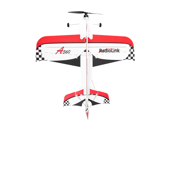


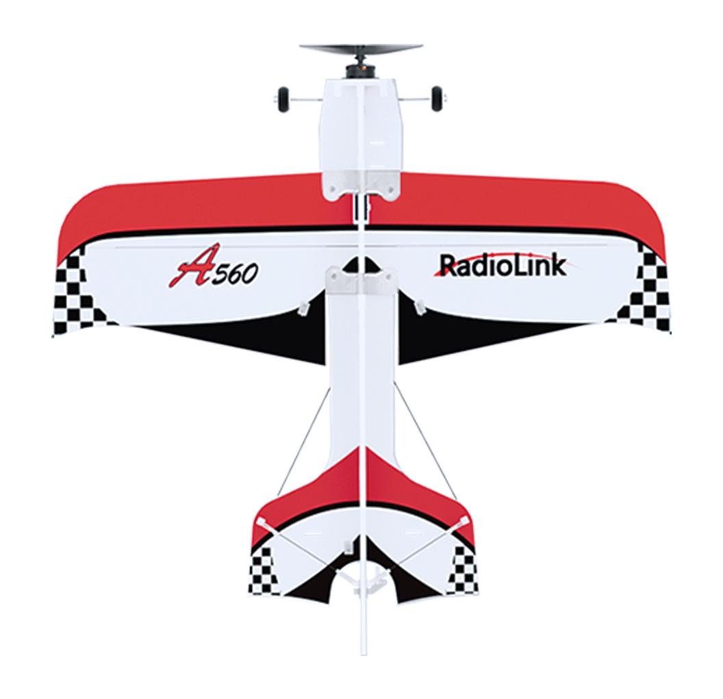
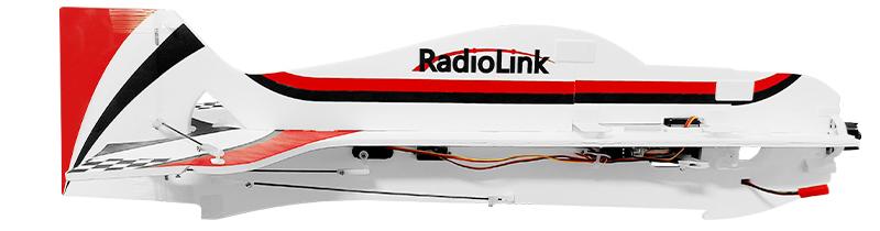
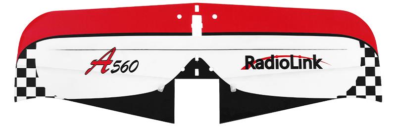
A560
Instruction Manual V2.0
使用说明书 V2.0
CE FCC RoHS
There are 2 versions of A560, including RTF version and PNP version.
Please refer to page 3-24 of this manual for RTF version, and page 25-29 for PNP version.
Disclaimer and Warning
Thank you for purchasing RadioLink 3D fixed wing A560.
To fully enjoy the benefits of this product and ensure safety, please read the manual carefully and set up the device as instructed steps. This product is not a toy and is NOT suitable for children under the age of 14. Adults should keep the product out of the reach of children and exercise caution when operating this product in the presence of children.
Inappropriate operation may causes property lose or accidental threats to life. Once the RadioLink product is operated, it means the operator understands this limitation of liability and accepts to take responsibility of the operation.
Make sure to follow the local laws and agree to follow the principles that made by RadioLink.
Fully understand that RadioLink cannot analyze the product damage or accident reason and cannot offer after-sales service if no flight record is provided. To the maximum extent permitted by law, RadioLink won’t take any responsibility about the lose caused by indirect/consequent/accidental/special/penal damages including the lose by purchase, operation and failure of operation in any instances. Even RadioLink is informed about the possible lose in advance.
Laws in certain countries may prohibit the exemption from the terms of the guarantee. Therefore consumer rights in different countries may vary.
In compliance with laws and regulations, RadioLink reserves the right to interpret the above terms and conditions. RadioLink reserves the right to update, change or terminate these terms without prior notice.
Warning
1. Please do not fly in the rain! Rain or moisture may cause flight instability or even loss of control. Never fly if there is lightning. It is recommended to fly in conditions with good weather (No rain, fog, lightning, wind).
2. When flying, you must strictly abide by local laws and regulations and fly safely! Do not fly in no-fly areas such as airports, military bases, etc.
3. Please fly in an open field away from crowds and buildings.
4. Please be very careful when flying indoors. You can fly in Vertical Mode for small venues. The specific flight mode should be determined according to the size of the flight venue.
5. Do not perform any operation under the condition of drinking, fatigue or other poor mental state. Please operate in strict accordance with the product manual.
6. Please be cautious when flying near electromagnetic interference sources, including but not limited to: high-voltage power lines, high-voltage transmission stations, mobile phone base stations and TV broadcast signal towers. When flying in the above-mentioned places, the wireless transmission performance of the remote control may be affected by interference. If there is too much interference, the signal transmission of the remote control and the receiver may be interrupted, resulting in a crash.
Packing List
Items |
Picture |
PNP |
RTF |
Fuselage PP 5mm 560mm |
|
1 |
1 |
Wing PP 5mm 580mm |
|
1 |
1 |
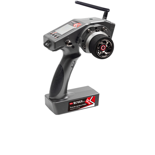
RadioLink Transmitter T8S |
|
0 |
1 |
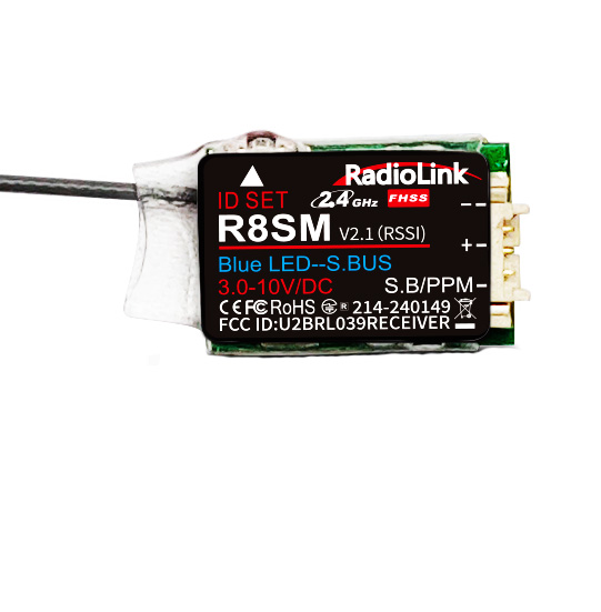
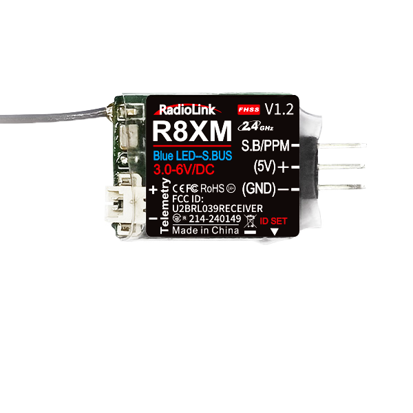
RadioLink Receiver R8XM |
|
0 |
1 |
RadioLink Flight controller Byme-A V2.0 |
|
1 |
1 |
2S 7.4V LiPo Battery |
|
1 |
1 |
2200KV Motor |
|
1 |
1 |
15A brushless ESC |
|
1 |
1 |
Propellers, dia.7mm |
|
2 |
2 |
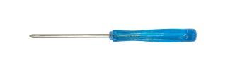
Aileron Servo, with 54mm Rudder Arm |
|
1 |
1 |
4.3g Tail Servo |
|
2 |
2 |
RadioLink Balance Charger CM210 for 2S LiPo Battery |
|
0 |
1 |
Landing Gear |
|
1 |
1 |
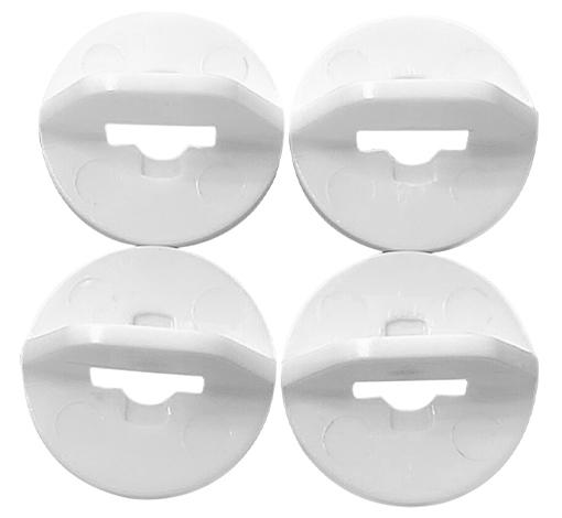
Button to fix wing |
|
4 |
4 |
Rudder Band to fix propeller |
|
5 |
5 |
|
1 |
1 |
|
|
1 |
1 |
|
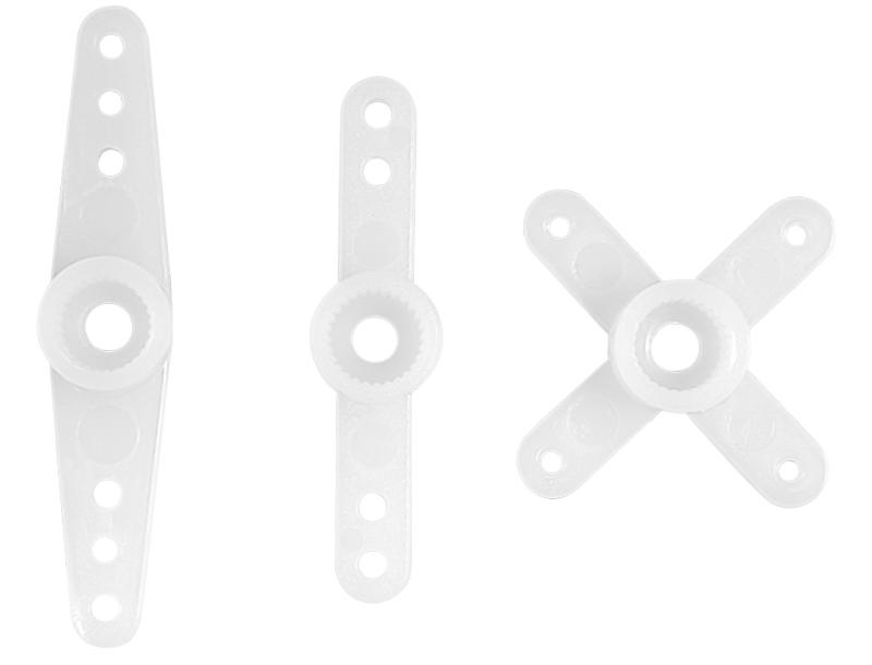
Spare Clasp for drawbar/rod |
|
2 |
2 |
Spare Rudder Angle |
|
3 |
3 |
Assembly & Disassembly Instruction |
|
1 |
1 |
Instruction Manual |
|
1 |
1 |
Waterproof Package(With shoulder strap) |
|
1 |
1 |


Chapter 1 General Introduction
1.1 Motion Principle of Fixed Wing
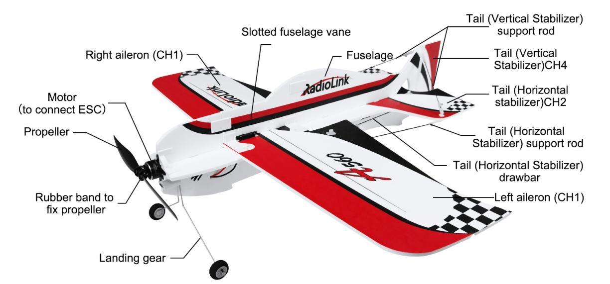
As below picture shown, besides the propeller, the two ailerons/horizontal tail/vertical tail are also the moving parts of A560.

1.1.1 Aileron
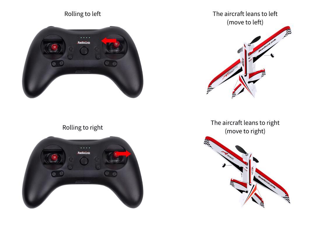
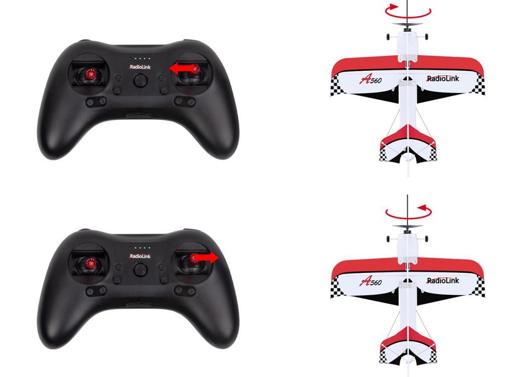
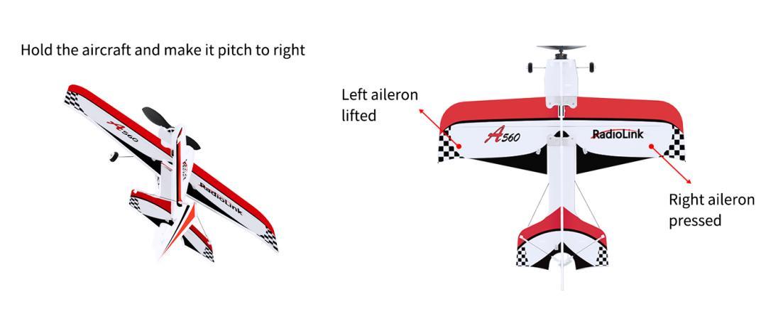
Ailerons are controlled by a servo. When the left aileron moves up and the right down, left aileron gets pushed by airflow downward and the right aileron is pushed by airflow upward, then A560 will lean to left or roll over to left. When the left aileron moves down and the right up, left aileron gets pushed by airflow upward and the right aileron is pushed downward, then A560 will lean to right or roll over to right.
1.1.2 Elevator Servo/Horizontal Tail
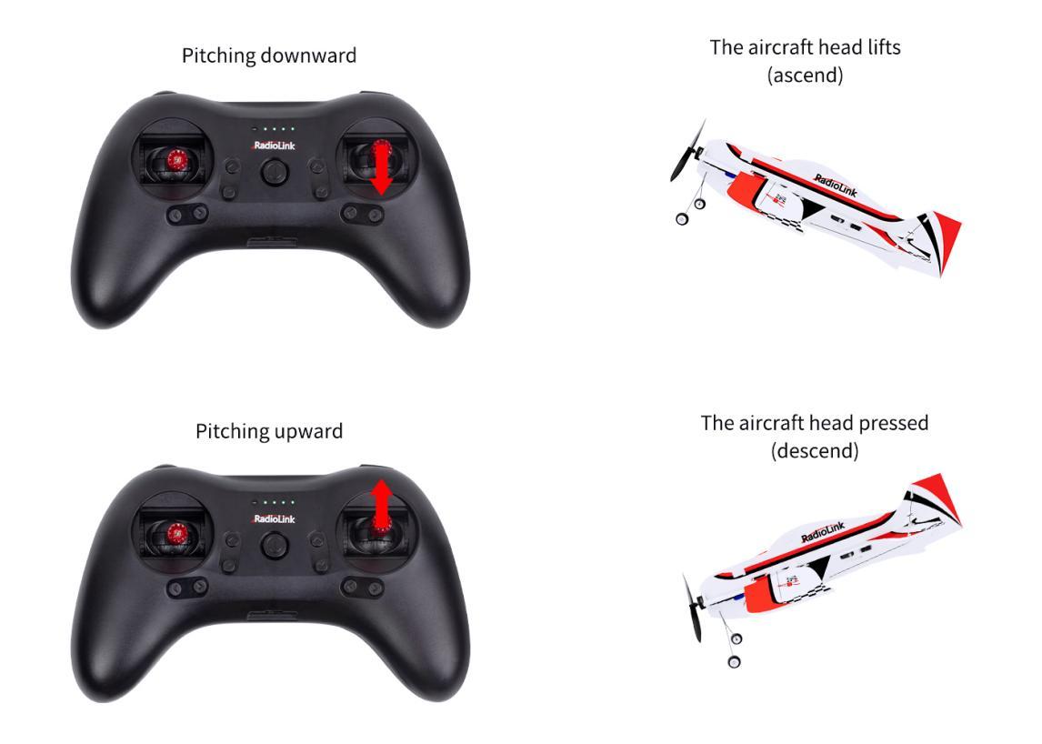
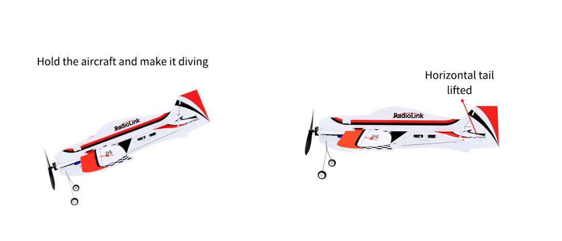
When the elevator servo moves upward, the horizontal tail gets pushed downward by airflow and the head of A560 will go up. When the elevator servo moves downward, the horizontal tail gets pushed upward by airflow and the head of A560 will go down.
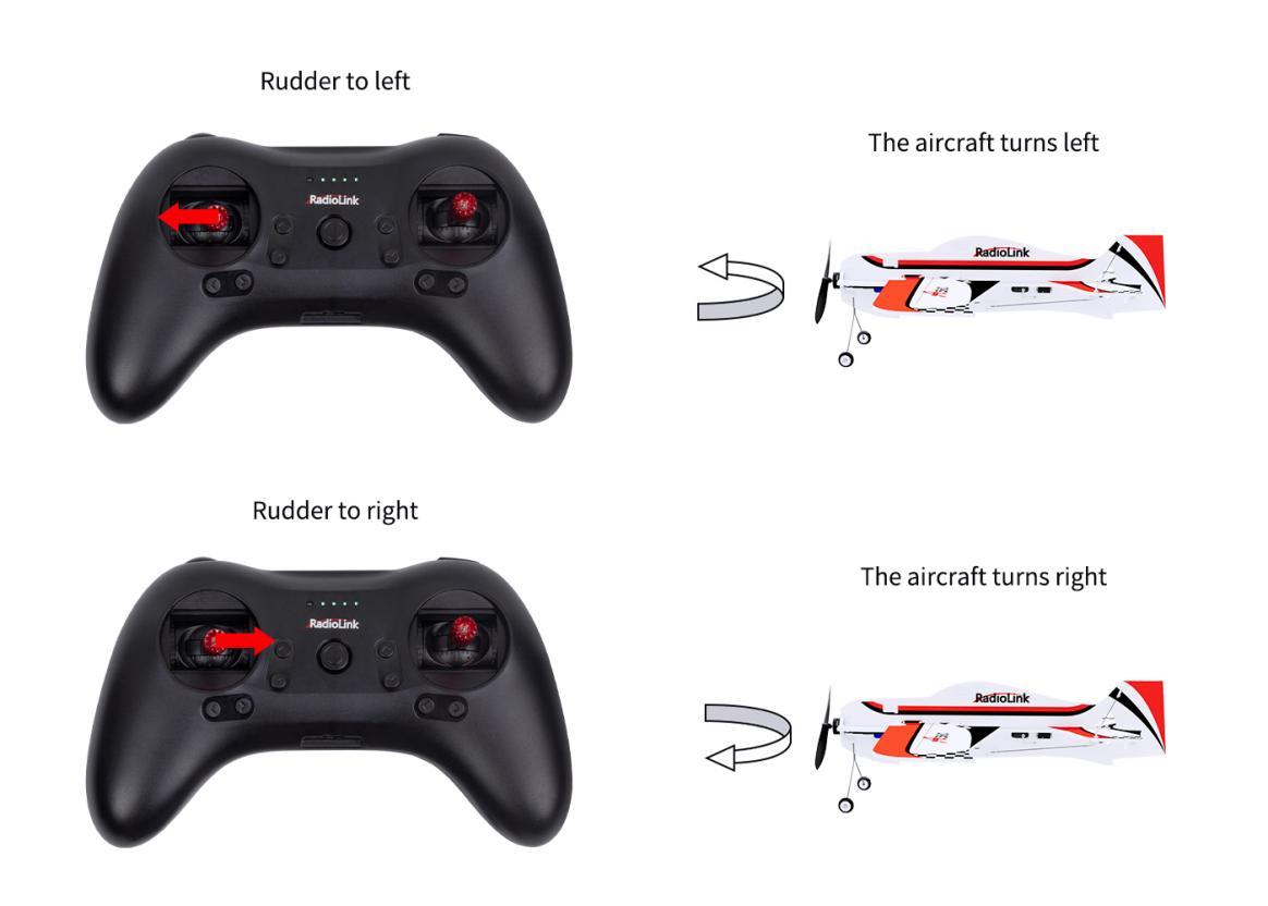
1.1.3 Rudder Servo/Vertical Tail
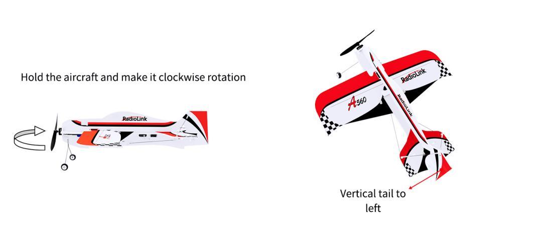
Similar to elevator servo, when rudder servo moves left, the vertical tail gets pushed to right by airflow and the head of A560 will turn left. When rudder servo moves right, the vertical tail gets pushed to left and the head of A560 will turn right.
Note The direction mentioned above is relative to aircraft instead of the ground. That is, if the aircraft is reversed (body upside down), its above is the ground instead of the sky/ceiling. When there’s no flight controller assisting or at MANUAL MODE, if maximize the elevator servo, the aircraft will roll over like roller coaster instead of moving upward. When under the assistance of the flight controller with VERTICAL MODE or STABILIZE MODE, the max pitch angle is limited. The aircraft will keep heading upward instead of rolling over if the elevator servo is maximized.
Besides, the function of all servos are related to the motor/throttle (propeller rotation speed). Because if the aircraft moves faster, the airflow applies more force on the servos.
1.1.4 Drive Principle
Servo outputs signal and voltage by receiver and adjust corresponding angle in real time. Generally, angle that servo can adjust is no more than 90°.
1.2 A560 Units
1.3 Usage of A560 Units
1.3.1 Notice for Use
No foreign matter such as water, oil, sand etc inside the A560.
Make sure the complete device incl. A560 and transmitter, battery functions well.
Never self-change the aircraft or related parts. Or it may influence its functionality and possibly cause flight accident.
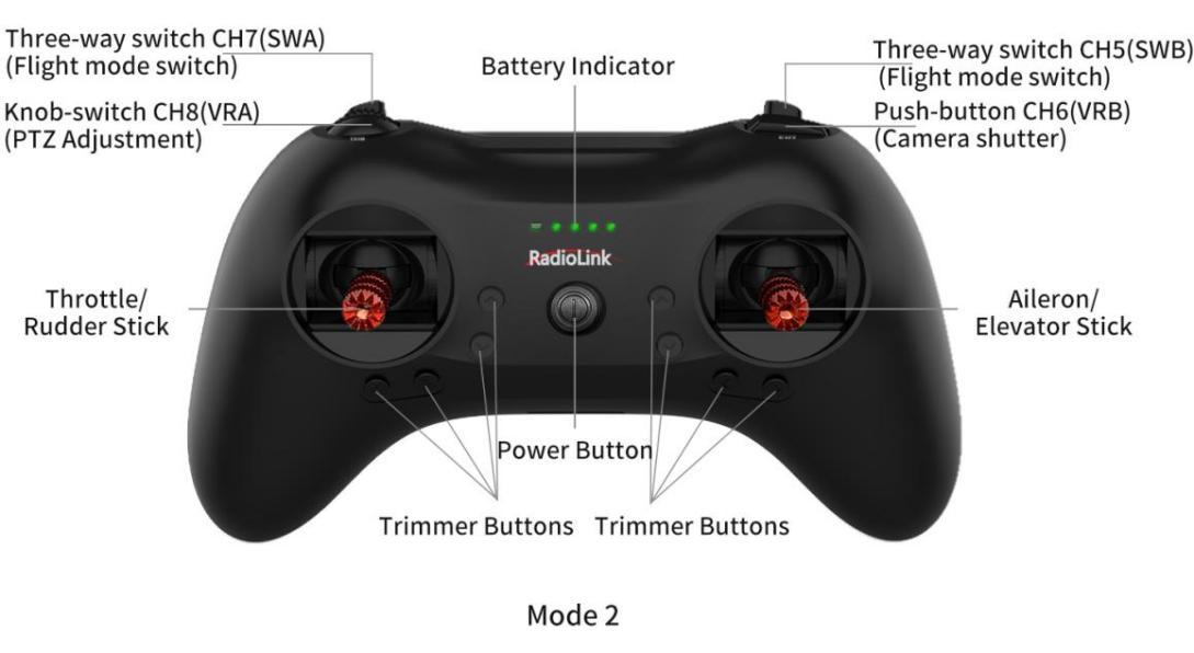
1.3.2 Transmitter & Receiver
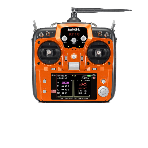
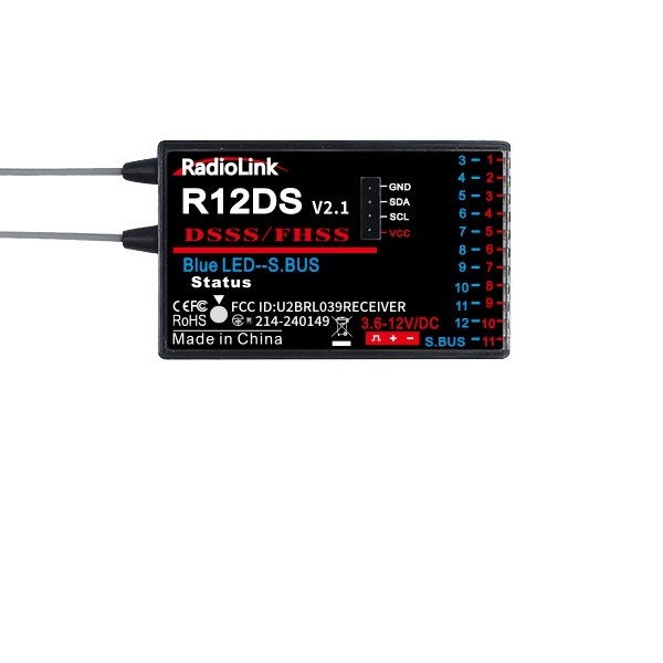
A560 RTF(Ready To Fly) is packed with RadioLink 8-channel transmitter T8S and mini receiver R8XM, with the stable control distance up to 4000 meters and real-time built-in telemetry function. (Maximum range tested in unobstructed areas free of interference and may vary depending on local regulations.)
If it is the PNP version purchased, please refer to the manuals of the transmitter and receiver used for more details.
Joystick Mode
To beginners, it’s very important to understand what joysticks connect to different channels and choose the most suitable mode .
First, throttle is controlled by toggling joystick up(top-max 100%) and down (bottom-min 0%). Below explanation takes MODE 2 with throttle joystick on left as example.
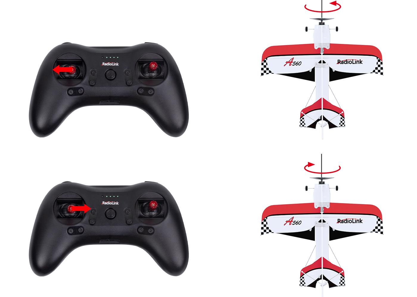
Left Joystick: Toggle up and down to control the motor (up as accelerate while down as decelerate). Toggle left and right to control the rudder (left as anticlockwise while right as clockwise).
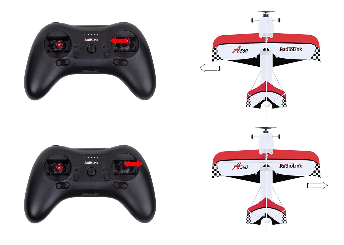
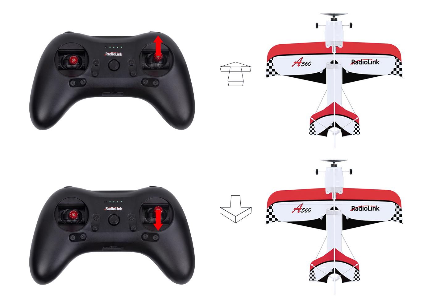
 Right Joystick: Toggle up and down to control the elevator servo(up as descend while down to lift the fixed wing). Toggle left and right to control the aileron servo( left to make the fixed wing rolling to left while right as rolling to right)
Usage of T8S Transmitter:
Make sure the transmitter power is fully charged.
If transmitter is changed, binding process needs to be redone before use. Please refer to the user manual of T8S for more details. You can visit RadioLink official website for detailed user manual of T8S: https://www.radiolink.com/t8s_manual
Make sure to power off the A560 before the transmitter when landing.
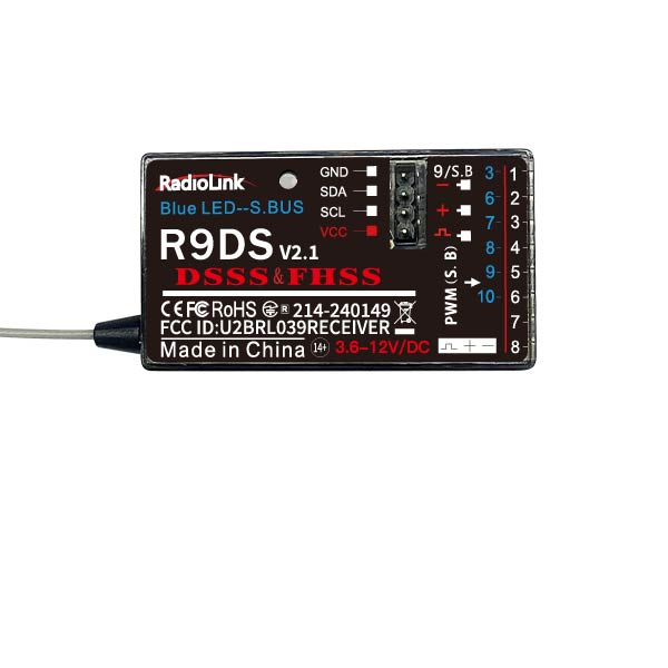
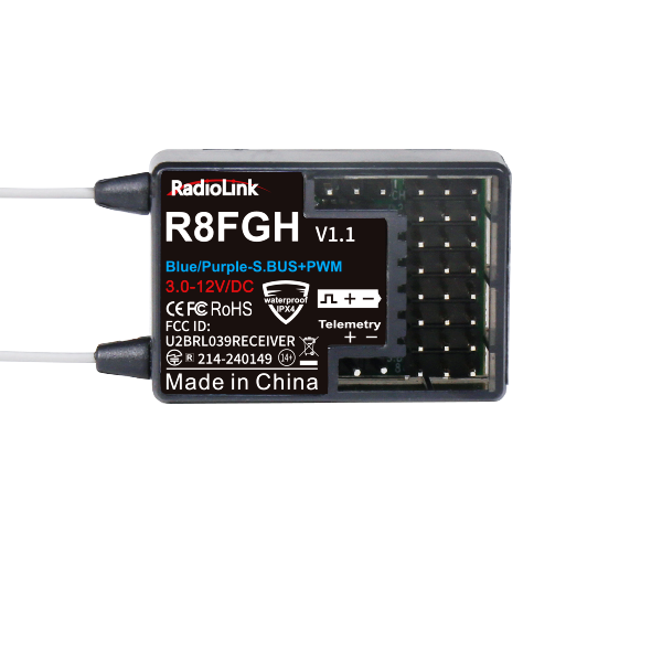
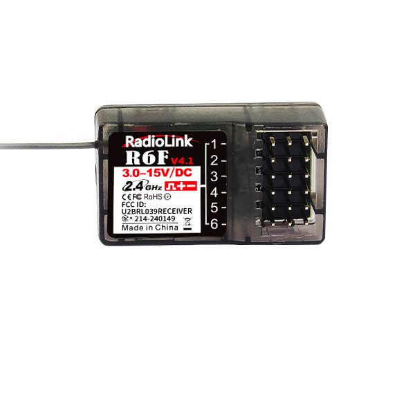
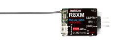
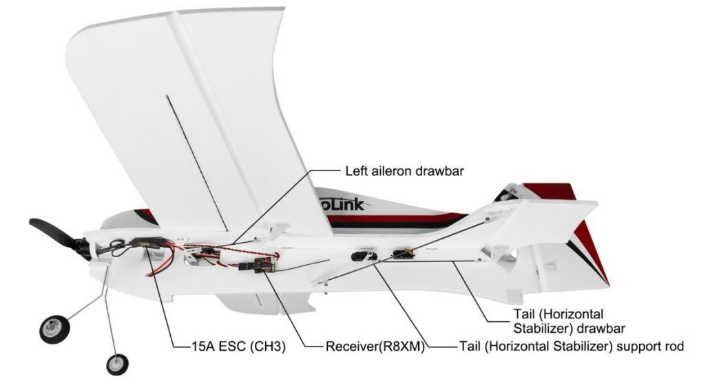
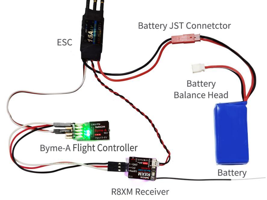
The standard packed receiver of A560, R8XM supports real-time transmission of RSSI, receiver voltage, and model voltage. The telemetry range is the same as the control range, 4000 meters. Connect the balance head of the battery to the telemetry port of R8XM, the model voltage will be displayed. (For A560 RTF, the telemetry port of R8XM is connected to ESC directly, with no need to connect it to the battery balance head.) And R8XM supports up to 6S (25.2V) battery voltage telemetry.
When the returned RSSI, receiver voltage, and model voltage are lower than the set alarm value, the transmitter will emit alarm tone:
Low transmitter voltage alarm: keep DDDD beep quickly and continuously
Low receiver voltage alarm: five DDDDD beeps as a unit continuous beeping prompt
Low model voltage alarm: three DDD beeps as a unit continuous beeping prompt
Low RSSI alarm: four DDDD beeps as a unit continuous beeping prompt
The returned model voltage alarm is set to 7.4V (2S battery) by default. When the battery voltage of A560 is lower than 7.4V, the transmitter will emit three DDD beeps to alarm.
For detailed manual of R8XM receiver, please check it on RadioLink official website: https://www.radiolink.com/r8xm_manual
Note: The telemetry range of R8XM receiver, which comes with new A560 is the same as the control range of 4000 meters, and the signal is strong. so it is best to keep the transmitter and R8XM receiver more than 50 centimeters apart when binding. If the transmitter and R8XM receiver are too close, it is easy to cause signal blockage, and the binding cannot be successful. After the binding is successful, there will also be signal block if they are two close to each other. For example, when T8S is too close to A560, push the joystick and the aircraft may not respond. Please bring the transmitter and R8XM receiver farther apart, the signal loss will disappear automatically.
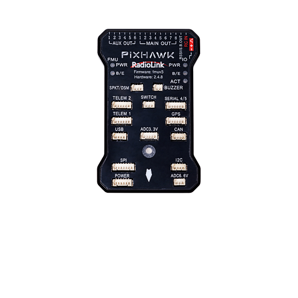
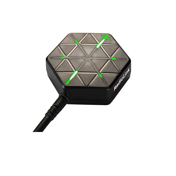
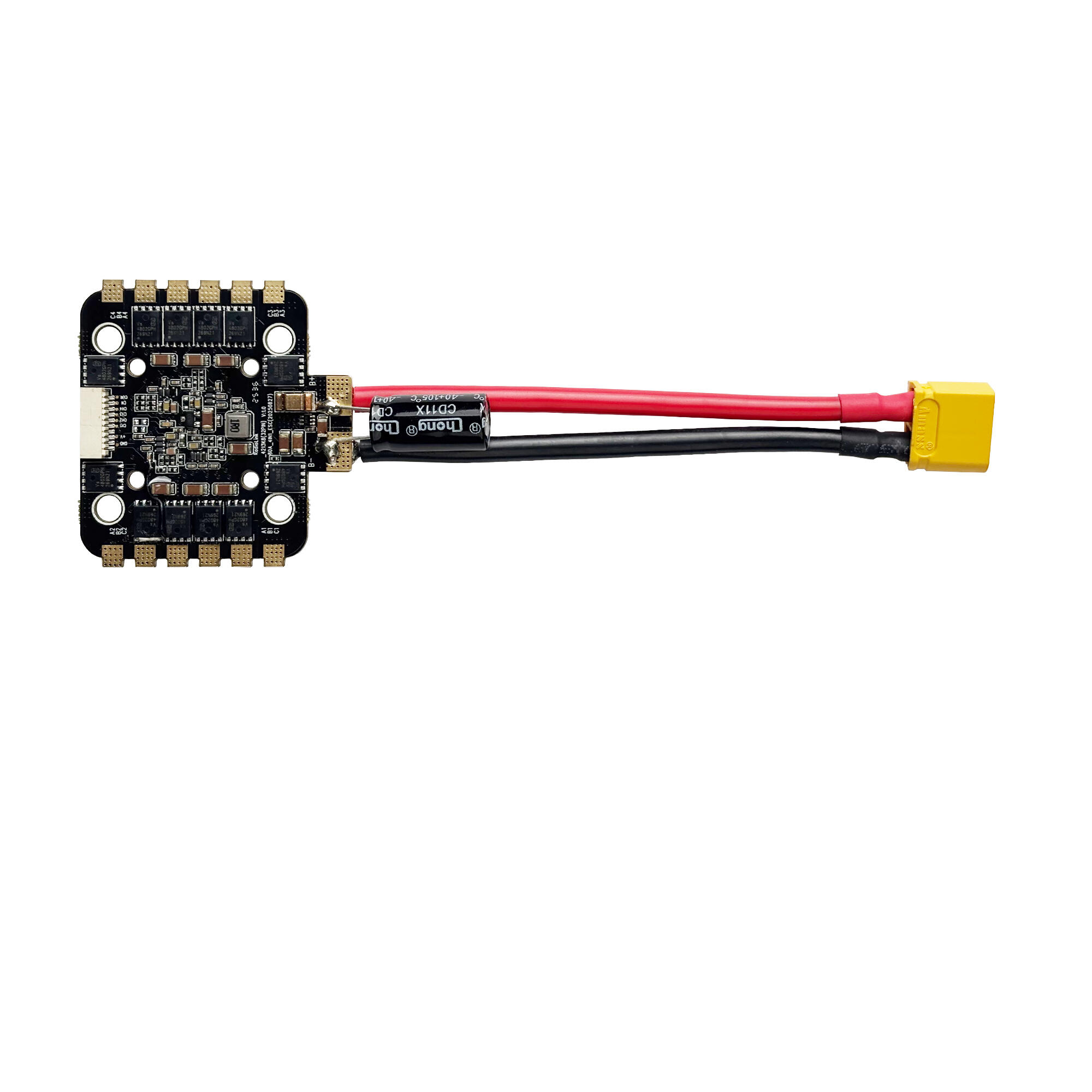
1.3.3 Flight Controller Byme-A V2.0
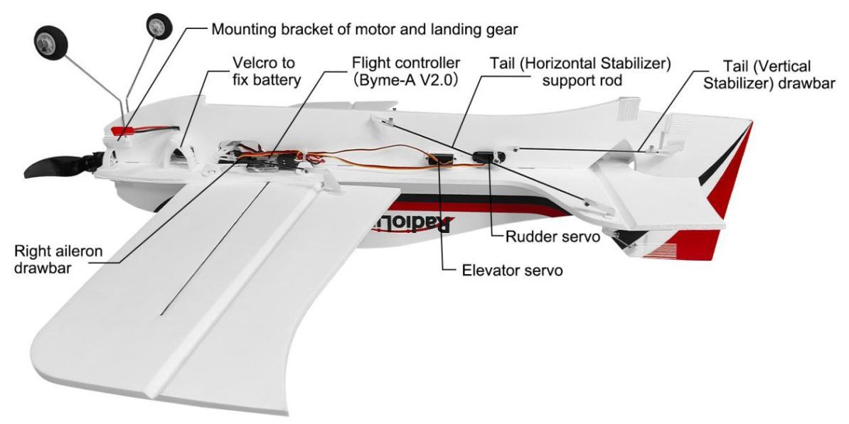
A560 RTF version is with flight controller Byme-A V2.0 installed by default. When installing or replacing the flight controller, make sure the arrow on Byme-A V2.0 points to the A560 head with the 3M paste on the A560. It is advised to install the flight controller close to the core of the A560 and connect the servo wires, ESC and receiver cables to the corresponding flight controller pin.
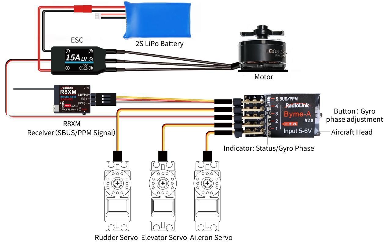
Channels on Byme-A V2.0 flight controller: CH1-Aileron, CH2-Elevator, CH3-Throttle, CH4-Rudder, S.BUS/PPM-connect to receiver, SBUS/PPM signal supported.
1.3.4 Motor
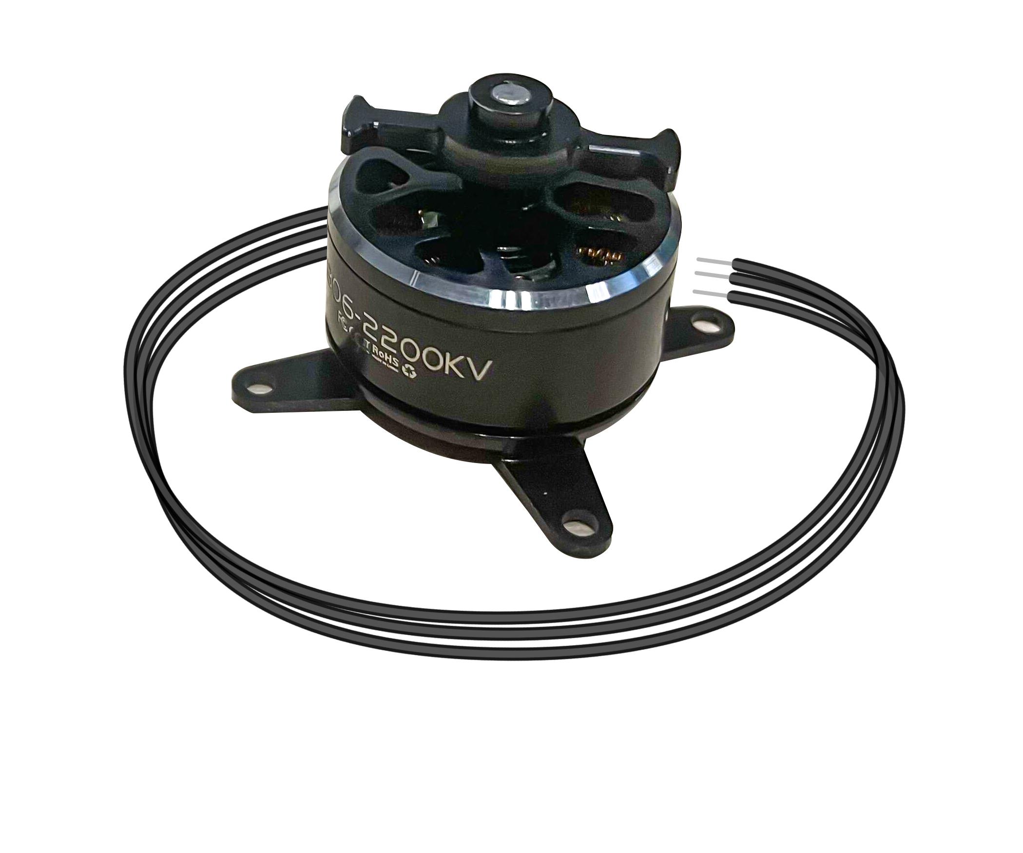
Motor installed on A560 is 2200KV brushless motor. (Motor with higher KV value, means higher rotation speed and smaller torsion force; Motor with lower KV value, means lower rotation speed and larger torsion force.)
Usage of Motor:
Make sure motors are installed tightly and rotate smoothly. If fail to rotate, stop operating transmitter immediately and pull the throttle to the bottom position in case of possible damage to motors.
Never self-change the motor structure.
When motors stop rotating, never touch it at once, otherwise may get burnt.
Never cover the air vent on the motor. Make sure no foreign matter inside the motors.
Make sure motors completely stop before powering off the A560 and the transmitter.
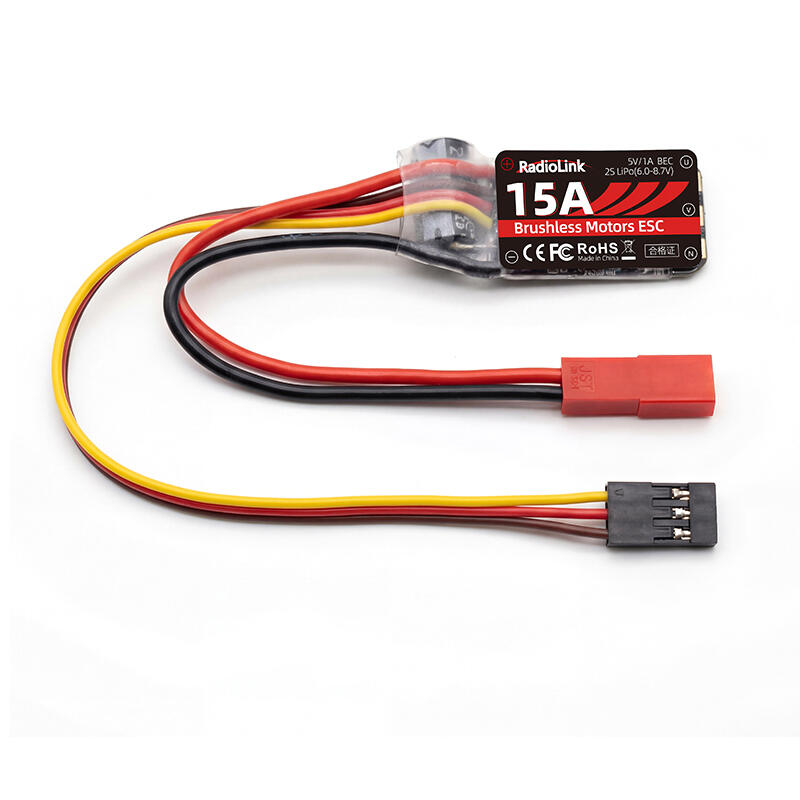
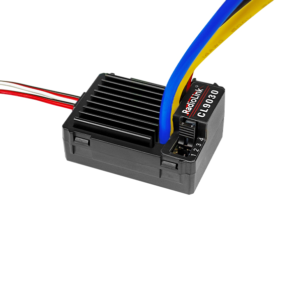
1.3.5 ESC
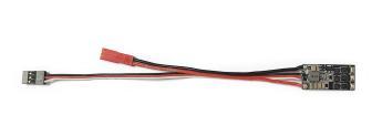
The function of ESC is to change the direct current to alternating one to power supply motor and change its rotation speed basing on the throttle command. Another function of ESC is to lower the model voltage to 5V for receiver as the battery applied for A560 is 7.4V 2S LiPo Battery. Therefore, there are three wires of ESC respectively for battery, motor and receiver. ESC applied in A560 is 15A brushless ESC.
Usage of ESC:
Make sure there’s a tone from ESC when power on the aircraft.
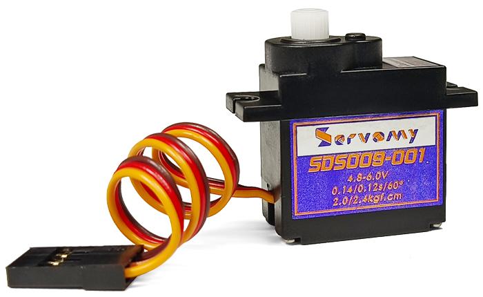
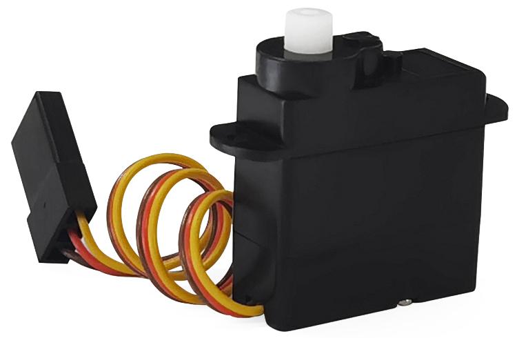
1.3.6 Servo
A560 uses an 8G servo as aileron servo and 2 pieces of 4.3G servo for elevator servo and rudder servo respectively.
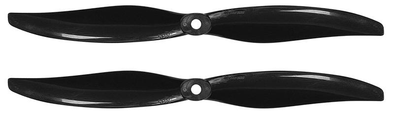
1.3.7 Propeller
A560 is packed with 2 propellers by factory default. If new propeller needs to be changed, fix the propeller and motor with a rubber band.
Propeller need to be identified correctly. If forward and reverse mistaken, the aircraft couldn’t take off even maximize the throttle. The rotation direction of motor and propeller should be the same. That is, if the motor rotates clockwise, so is the propeller.
Usage of propeller:
Make sure to check the propeller is in good condition before flight. If aged, damaged or deformed, please change to good one then flight.
Make sure to disconnect the power supply before touching the propeller.
As propeller is thin, use tools to (un)install if necessary and be careful to avoid accidental scratch.
Make sure propeller is installed well and tight before flight.
Do not get close to rotating propeller and motor (for example, to pick up a landing plane by hand ) to avoid cuts
1.3.8 Battery
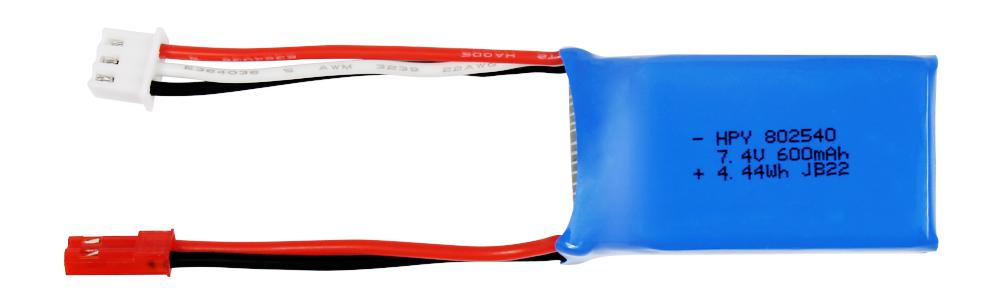
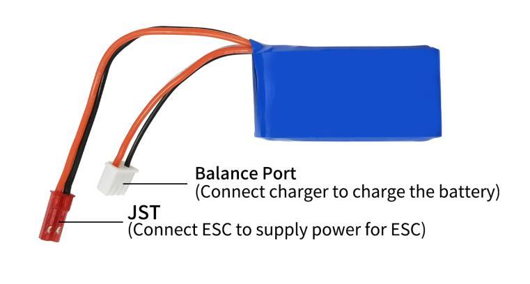 A560 supports 2S-3S LiPo battery. A560 is packed with 2S 7.4V 600mAh LiPo Battery. With the LiPo battery fully charged, pilots can enjoy vertical flight for 10 minutes while level flight for 20 minutes.
Usage of battery:
Make sure the power connection of transmitter and aircraft is dry.
Make sure the transmitter and aircraft are fully charged.
When the transmitter emits DDD beeps to alarm low battery voltage, if the power of the aircraft drops when the throttle is pushed, the battery voltage on the aircraft is insufficient. At this time, please return to the flight immediately to avoid the failure of the aircraft to return due to the insufficient power battery voltage and the over-discharge of the battery.
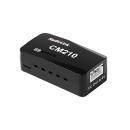
1.3.9 Charger
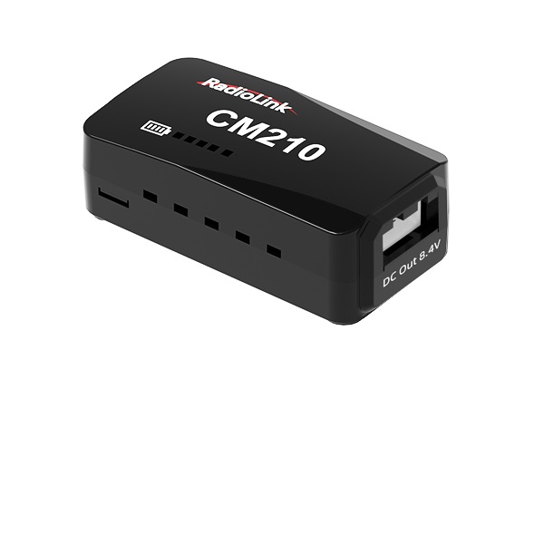
A560 is packed with RadioLink CM210 balance charger (Only for 2S lipo battery) to charge the battery.
CM210 Specifications:
Size: 40.5*21*15 mmWeight: 9g
Input Voltage: 5VSupporting Battery: 2S LiPo battery
Charging Precision: 0.02VCharging Voltage: Max. 4.2V for each battery cell
Charging Current: 1.5ABalance Current: 0.8A
Max. Output Power: 20WPower Supply Input Port: USB Type-C Input
Charging Port Interface: 2S battery balance port
Working Modes: Charging Mode, Balance Mode, Repair Mode (Self-adaptive, with no need to set it)
The connection of CM210, battery, cable is as shown below:
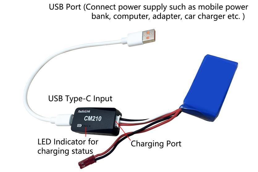
Instructions for using CM210 charger:
Insert one end of the standard USB cable into the Type-C input port of the CM210 charger (as shown in the picture above), and then connect the other end of the USB cable to power supply equipment such as power bank, computer, mobile phone adapter, etc.. After the right connection, the red LED indicator will be always on.
Insert the balance port of the standard 2S lithium battery of A560 into the charging port of CM210 (as shown in the picture above). Then the green LED indicator starts flashing, which means it starts to charge the battery. (Note: The green LED indicator flashes during the charging to indicate normal charging; If the red LED indicator flashes during the charging to indicate abnormal charging. Please reconnect battery and cable to troubleshoot the abnormality.)
When all four LED indicators turn solid green, the battery is fully charged, and the charger will automatically stop charging.
Remove the battery and then disconnect the power supply.
CM210 LED indicator status:
LED color |
Status |
Meaning |
Red |
Flash |
The charger detects abnormality. |
Always on |
No battery is connected. |
|
Green |
All four green LEDs flash once. |
The charger is powered on. |
The first green LED flashes, and the other LEDs are off. |
The battery voltage is lower than 7.4V. |
|
The first green LED is always on, and the second green LED is flashing. The other LEDs are off. |
The battery voltage is lower than 7.8V. |
|
The front two green LEDs are always on, and the third green LED is flashing. The other LEDs are off. |
The battery voltage is lower than 8.2V. |
|
The front three green LEDs are always on, and the fourth green LED is flashing. The other LED is off. |
The battery voltage is lower than 8.4V. |
|
All four green LEDs are always on. |
The battery is fully charged. |
Troubleshooting for CM210 charger:
1. After the charger is powered on, the red light flashes just after inserting the battery or within one minute.
The current detection resistor is burned out, and the MCU detects that the current is too large.
The switch tube is damaged, so it is unable to switch normally. There is no current output or the output current of the power supply is too small.
2. After the charger is powered on, insert the battery and charging works normally for a period of time, and then the red light flashes.
The output current of the power supply is too small, or the battery is damaged.
Solution: Replace the power supply or battery to charge it again, if the abnormal phenomenon still occurs, the charger is damaged.
Chapter 2 A560 Assembly
All electronic components of A560 are already set. If it’s the RTF version(with transmitter T8S and receiver packed), all you need to do after unpacking the box is to assemble the wing, and then fly it. Please follow the packed A560 Assembly & Disassembly Instruction to complete the assembly. You can also view the assembly tutorial on RadioLink official website:
https://www.radiolink.com/a560_video
Chapter 3 Flight Mode
3.1 Flight Mode Setting
With the three-axis gyroscope and three-axis acceleration sensor and the full attitude algorithm, control algorithm and digital filter, the integrated flight controller Byme-A V2.0 specially for 3D fixed wing, is different from traditional manual mode. Working with gyro to assist stabilization, Byme-A V2.0 makes the flight much easier.
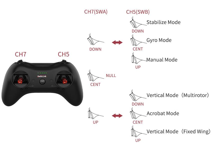
There are six flight modes: Stabilize Mode, Gyro Mode, Manual Mode, Acrobat Mode, Vertical Mode(Multirotor), and Vertical Mode(Fixed Wing).
No. |
Flight Mode |
Brief |
1 |
Stabilize Mode |
Flight controller assists to balance A560. When joystick back to center, A560 will back to level. There’s max roll angle/pitch angle. |
2 |
Gyro Mode |
flight controller assists to balance A560. When joystick back to center, A560 will NOT back to level. |
3 |
Manual Mode |
No flight controller or gyro assist to balance. The most advanced level for professionals. |
4 |
Acrobat Mode |
Combination of Stabilize Mode and Gyro Mode. When joystick is back to center, A560 will back to level. There’s NO max roll angle or pitch angle. Rolling over is possible. |
Vertical Mode (Multirotor) |
A560 can automatically keep the vertical attitude. One switch to flight vertically. In Vertical Mode (Multirotor), toggle the aileron joystick to control the A560 moving left or right, and toggle the rudder joystick to control the A560 moving (anti)clockwise. The joystick operation is same as that of multi-rotors. |
|
6 |
(Fixed Wing) |
A560 can automatically keep the vertical attitude. In Vertical Mode (Fixed wing), toggle the aileron joystick to control the A560 moving (anti)clockwise, and toggle the rudder joystick to control the aircraft moving left or right. |
 Flight modes are set by CH5(3-way switch SWB) and CH7(3-way switch SWA) by default.
3.2 Six Flight Modes
All the settings will take Mode 2 as example.
3.2.1 Stabilize Mode
Different form manually control, Stabilize Mode with flight controller balancing, is suitable for beginners to practice level flight.
The model attitude (inclination angles) is controlled by joysticks. When the joystick is back to central point, the A560 will level. The max inclination angle is 70° for rolling while that for pitching is 45°.
If the throttle is toggled upward, the A560 accelerate. If toggled downward, the A560 decelerate.
3.2.2 Vertical Mode (Multirotor)
Vertical Flight Mode can be changed with one switch and control as multicopter, pilots can make the fixed wing automatically fly with the vertical posture. Tutorial video can be checked via https://youtu.be/N2Gm4OUhu-c
At this mode, A560 will keep vertical attitude automatically. The attitude algorithm of flight controller will convert the joystick output to the horizontal coordinates and control with full posture.
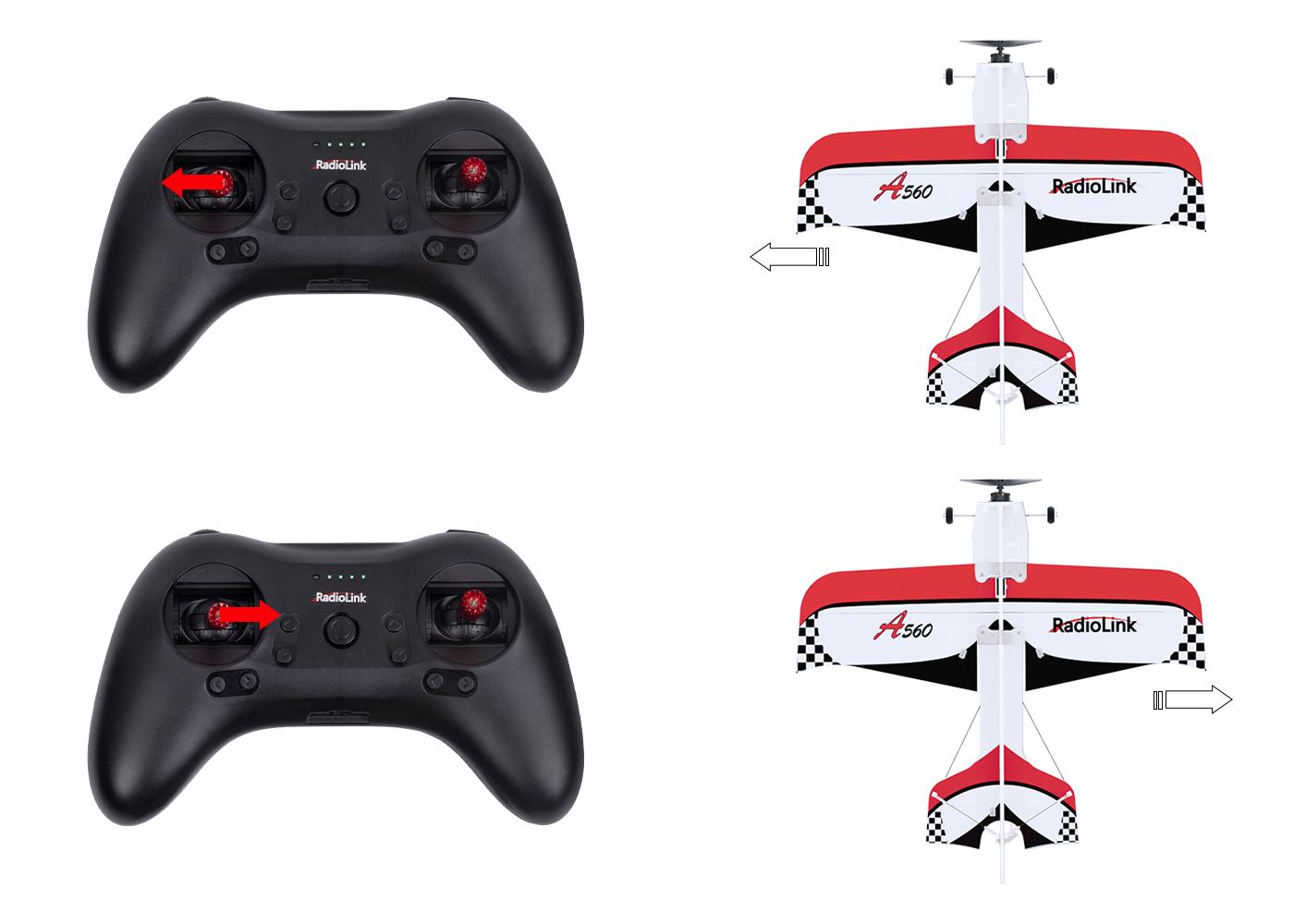
When the A560 is vertical, toggle the aileron joystick(CH1) to control the A560 moving left or right.
When the A560 is vertical, toggle the elevator joystick(CH2) to control the A560 moving forward or backward.
When the A560 is vertical, toggle the rudder joystick(CH4) to control the A560 moving (anti)clockwise.
If the throttle joystick is toggled upward, the A560 climbs upwards at a vertical attitude. If toggled downward, the A560 descends at a vertical attitude.
3.2.3 Vertical Mode (Fixed Wing)
At Vertical Mode (Fixed Wing), the A560 will remain vertical posture and direction.
The altitude algorithm of Byme-A V2.0 maps the joystick operation onto horizontal ordinates and takes control of full altitude.
 When the A560 is vertical, toggle the aileron joystick(CH1) to control the A560 moving (anti)clockwise.
When the A560 is vertical, toggle the elevator joystick(CH2) to control the A560 moving forward or backward.

When the A560 is vertical, toggle the rudder joystick(CH4) to control the aircraft moving left or right.
If the throttle joystick is toggled upward, the A560 climbs upwards at a vertical attitude. If toggled downward, the A560 descends at a vertical attitude.
3.2.4 Gyro Mode
At this more advanced mode, the integrated three-axis gyro assists to increase the stability. But A560 won’t level even the joystick is back to central point. The joystick control the rotation(angle speed) of the A560. That is, when rolling, pitching or rudder joystick is toggled, A560 will rotate with the corresponding speed.
3.2.5 Acrobat Mode
Combination of Stabilize Mode and Gyro Mode makes it easy to realize various free styles such as rolling, rapid pitching, backward, side flight and spiral descending.
A560 will level when the joystick is back to central point. If the joystick is toggled with small range, A560 will move to the corresponding directions.
When toggle joysticks with large range, A560 will rotate to the corresponding directions.
3.2.6 Manual Mode
No assistance from flight controller algorithm or gyro, all flight movements are realized manually, which requires the most advanced skills.
It’s strongly advised for beginners to choose Vertical Mode or Stabilize Mode to practice. Or if in small space, Vertical Mode can be set to take off and land then switch to level flight(Stabilize Mode/Gyro Mode/Acrobat Mode/Manual Mode) when reach a certain height. If switch to other flight modes from Vertical Mode, remember to pull the elevator joystick to ensure rising of A560. Otherwise the A560 will crash.
When at Vertical Mode, the joystick operation is same as that of multi-copters.
When at Stabilize Mode/Gyro Mode/Acrobat Mode/Manual Mode, the joystick operation is standard one of fixed wing. Beginners have better to practice with simulators and get familiar to the operations of aileron/elevator/throttle/rudder joysticks in advance.
Chapter 4 Flight Precautions
1. Check before take-off to make sure that all parts are in good working condition.
2. Make sure that the buttons(to fix aileron/tail) are firmly fixed to avoid the crash caused by the loose buttons.
3. Make sure the battery is fully charged and properly bound to the fuselage before take-off.
4. Make sure that the front and back of the propeller are installed correctly and the propeller is not inclined.
5. Keep A560 face up, rather than upside down during power-on calibration and attitude calibration.
6. After the setting of channel direction in the transmitter, please calibrate the attitude once. Then switch to the manual mode, and push the joystick to check whether the movement of the control surface is correct. If it is not, please change the direction of the corresponding channel on the flight controller.
7. In Stabilize/Gyro/Acrobat mode, the aileron may swing by itself to assist the balance due to the gyroscope involved in stabilization, which is a normal phenomenon.
8. In Manual mode, it is normal that there is no movement of the control surface without any operation on the transmitter because there is no gyroscope involved in stabilization.
9. If flying indoors, please choose the Vertical mode. Six flight modes are available for outdoor flight. It is recommended that novices choose the Stabilize mode for take-off and practice.
10. It is recommended to change another battery to avoid over-discharge of the battery when the transmitter emits DDD beeps to alarm low battery voltage.
11. If there is any abnormality during the flight, please land immediately and find out the reason.
Chapter 5 Power-on and Gyro Self-test
Each time the flight controller is powered on, the gyro of the flight controller will perform self-test with the green LED quickly flashing, which means gyro self-test is under process. Therefore, it is recommended to install the battery first, then place the aircraft on the ground, and then power on the aircraft and put the aircraft still on the ground until DEE sounds from the motor heard. When the green LED is always on means self-test is done.
Note: Push the throttle stick of the transmitter to the lowest position first, and then power on the aircraft. If the throttle stick is pushed to the highest position and then power on the aircraft, the ESC will enter the calibration mode.
Chapter 6 Attitude Calibration
Flight controller Byme-A V2.0 needs to calibrate the attitudes/level to ensure the balance status.
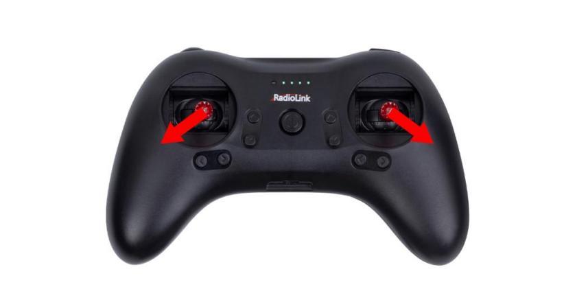
(1) The aircraft can be placed flat on the ground when performing attitude calibration. It is advised to lift the model head with a certain angle(20 degree is advised) for beginner to ensure the calibration accuracy and attitude calibration will be recorded by flight controller once the it is complete with success.
(2) Push the left stick (left and down) and the right stick (right and down) as below and hold more than 3 seconds. The green LED flashes once mean the calibration completed. It is also normal for the control surface to swing or the motor to rotate once at this time.
Chapter 7 Gyro Phase
7.1 Gyro Phase Test
Make sure attitude calibration is done before gyro phase test. Because flight controller will auto identify NOR/REV and modify gyro direction when doing attitude calibration.
At Stabilize Mode, hold the A560 and simulate the actual flight movement to check the gyro phase of aileron, elevator, and rudder are right or not. There is no need to operate the transmitter when testing the gyro phase. The movement of aileron, elevator, and rudder at Stabilize Mode are opposite to that at Manual Mode because the gyro will help A560 keep balancing.
In Stabilize Mode, if the gyro phase is reversed, please adjust the gyro phase by the flight controller Byme-A V2.0. See the below chapter for the adjustment method.
7.2 Gyro Phase Adjustment
If gyro phase is reversed, the phase needs to be adjusted by the flight controller. Press the button on the front of the flight controller Byme-A V2.0 to change the gyro phase. The adjustment method is as follows:
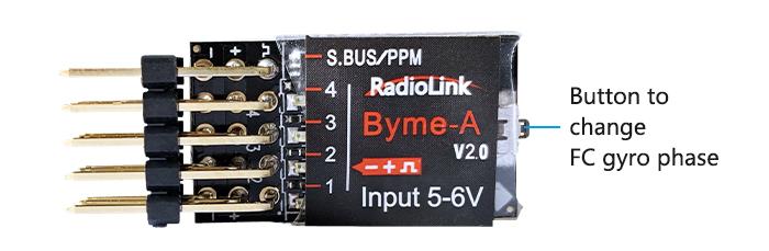
No. |
Channel |
If gyro phase is reversed |
Indicator LED |
1 |
AILERON |
Short press the button once |
Green LED of CH1 on/off |
2 |
ELEVATOR |
Short press the button twice |
Green LED of CH2 on/off |
3 |
THROTTLE |
N/A |
Green LED always on |
4 |
RUDDER |
Short press the button four times |
Green LED of CH4 on/off |
Note : Neither the always-on nor off green LED means reversed phase. Only toggle the joysticks can check if the corresponding servo phases are reversed. If the gyro phase of the flight controller is reversed, adjust the gyro phase by pressing the buttons on the flight controller.
Chapter 8 Transmitter Setup
8.1 Transmitter Phase Setup
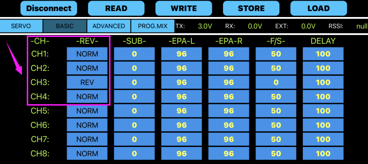
A560 RTF version has already set up transmitter phase, but please check it again before taking off. Please check the transmitter phase in T8S Parameter Setup APP. Enter the basic menu. Set CH1/CH2/CH4 to NORM, and CH3 to REV, as shown below:
Click https://www.radiolink.com/t8s_appshttps://www.radiolink.com/t8s_manual to download T8S Parameter Setup APP for Android mobile phone。For Apple mobile phone, please search for "T8S" in App Store to download T8S Parameter Setup APP. Please click https://www.radiolink.com/t8s_appshttps://www.radiolink.com/t8s_manual to download the detailed manual of T8S in RadioLink official website.
8.2 Transmitter Phase Test
Make sure the transmitter phases are correct before flight. All the settings will take Mode 2 as example. Please check the transmitter phase at Manual Mode.
At Manual Mode, put the aircraft on the ground and keep horizontal. Check the phase of aileron, elevator, and rudder by pushing the joysticks of transmitter.
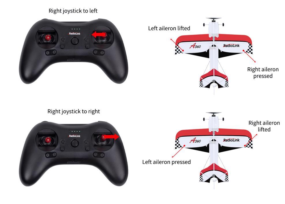
Toggle the aileron joystick to left, left aileron is lifted and right one is pressed; toggle the joystick to right, left aileron is pressed and right one is lifted.
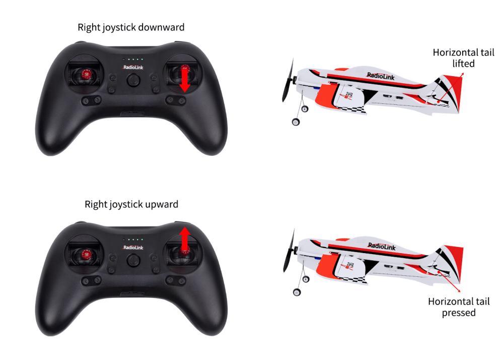
Toggle the elevator joystick downward, elevator servo(horizontal tail) is lifted; toggle the joystick upward, elevator servo(horizontal tail) is pressed.
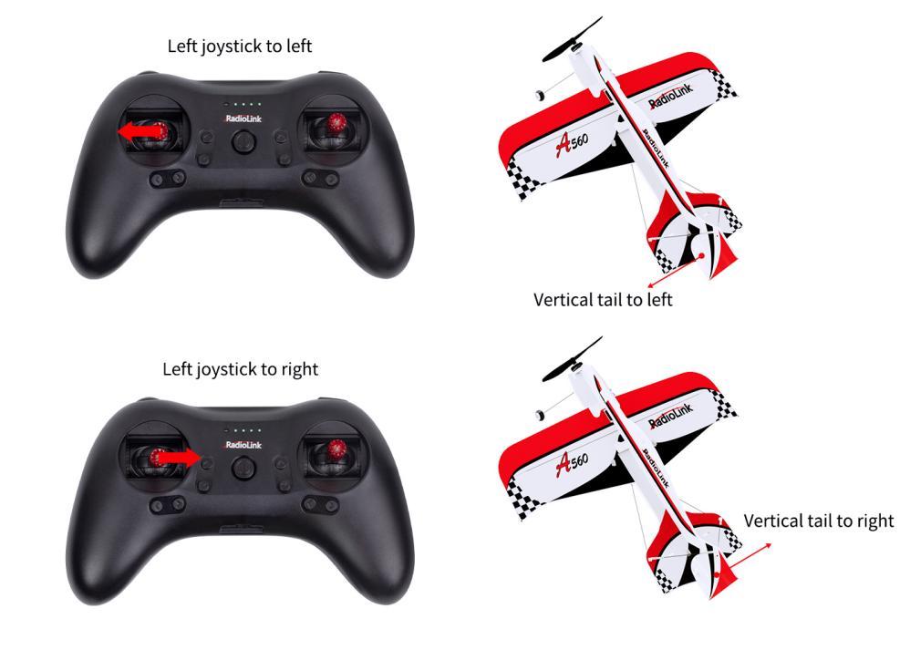
Toggle the rudder joystick to left, rudder servo(vertical tail) turns to left; toggle the joystick to right, rudder servo(vertical tail) turns to right.
In manual mode, operate the joystick of the transmitter. If the movement of the control surface of the corresponding channel is reversed, enter the setting page of the transmitter to adjust the transmitter phase of the corresponding channel.
A560 (PNP) Instruction Manual
Disclaimer and Warning
Please refer to A560 RTF Disclaimer and Warning.
Packing List
Please refer to A560 RTF Packing List.
Chapter 1 General Introduction
Please refer to A560 RTF Chapter 1 General Introduction.
Chapter 2 A560 Assembly
2.1 A560 Assembly
Please refer to A560 RTF Chapter 2 A560 Assembly.
2.2 Receiver Connection
For A560 PNP version, transmitter and receiver needs to be installed. A560 is compatible to all transmitters that supports SBUS/PPM signal.
First, install the receiver on A560 aircraft. Make sure the receiver is switched to SBUS/PPM signal mode, and then connect the receiver to Byme-A V2.0 flight controller. For the connection method of the receiver, please refer to A560 RTF Chapter 1.3.3 Flight Controller.
Second, calibrate the throttle range of A560 ESC. The normal Start-up and Throttle Range calibration steps of A560 ESC are as follows:
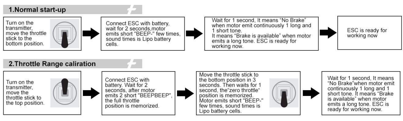
For more information on how to use A560 ESC, please visit RadioLink official website:
https://www.radiolink.com/manuals_download
Chapter 3 Flight Mode
3.1 Flight Mode Setting
With the three-axis gyroscope and three-axis acceleration sensor and the full attitude algorithm, control algorithm and digital filter, the integrated flight controller Byme-A V2.0 specially for 3D fixed wing, is different from traditional manual mode. Working with gyro to assist stabilization, Byme-A V2.0 makes the flight much easier.
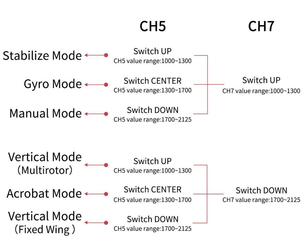
There are six flight modes: Stabilize Mode, Gyro Mode, Manual Mode, Acrobat Mode, Vertical Mode(Multirotor), and Vertical Mode(Fixed Wing). Flight modes are switched by CH5(3-way switch) and CH7(2-way switch) by default. The value range of channel 5 and channel 7 corresponding to the flight mode is as shown below:
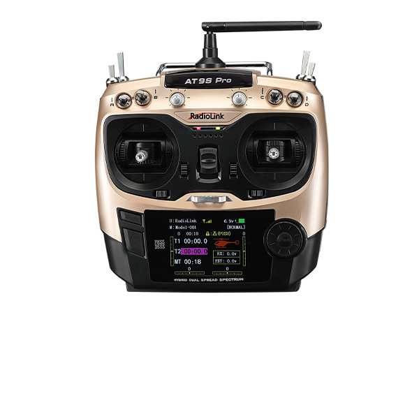
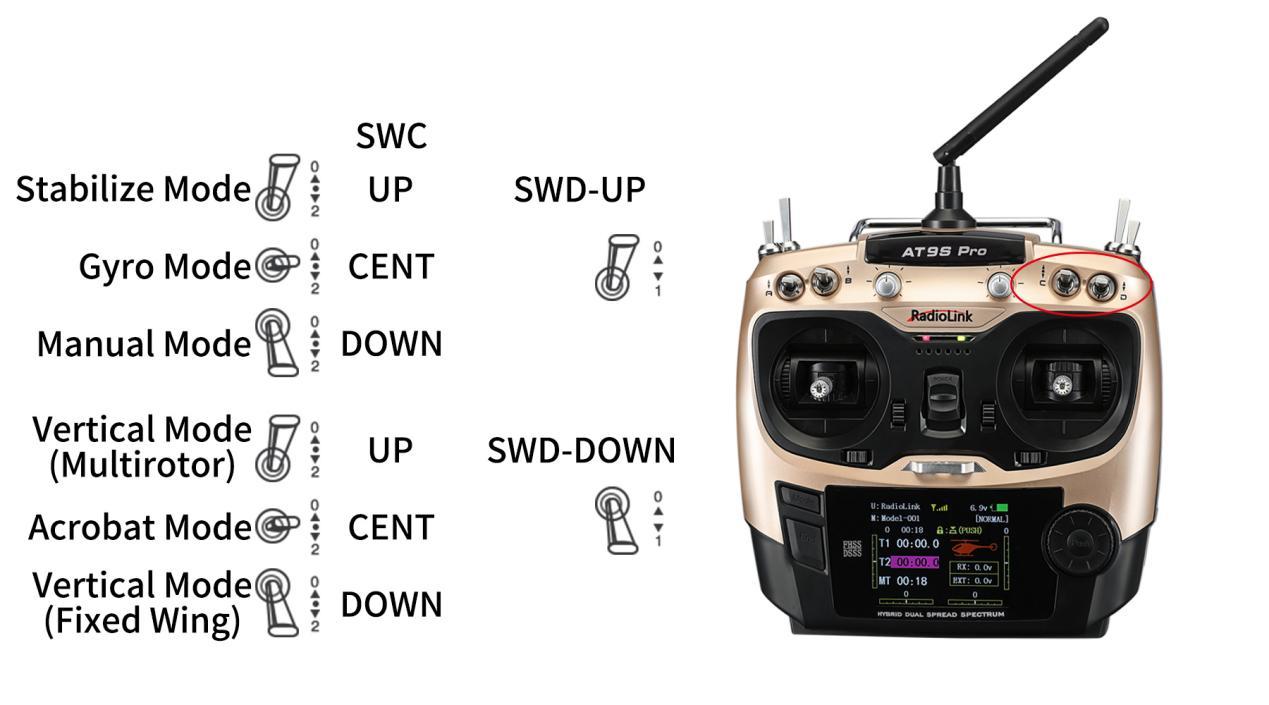 Take RadioLink AT9S Pro transmitter as example. Flight modes are set by CH5(3-way switch SWC) and CH7(2-way switch SWD) as below.
3.2 Six Flight Modes
Please refer to A560 RTF Chapter 3.2 Six Flight Modes.
Chapter 4 Flight Precautions
Please refer to A560 RTF Chapter 4 Flight Precautions.
Chapter 5 Power-on and Gyro Self-test
Please refer to A560 RTF Chapter 5 Power-on and Gyro Self-test.
Chapter 6 Attitude Calibration
Flight controller Byme-A V2.0 needs to calibrate the attitudes/level to ensure the balance status.
(1) The aircraft can be placed flat on the ground when performing attitude calibration. It is advised to lift the model head with a certain angle(20 degree is advised) for beginner to ensure the calibration accuracy and attitude calibration will be recorded by flight controller once the it is complete with success.
(2) Push the left stick (left and down) and the right stick (right and down) as below and hold more than 3 seconds. The green LED flashes once mean the calibration completed. It is also normal for the control surface to swing or the motor to rotate once at this time.
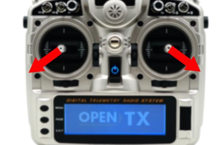
Note: When using a non-RadioLink transmitter, if the attitude calibration is unsuccessful when pushing the left stick (left and down) and the right stick (right and down), please change the direction of the channel in the transmitter. Make sure when pushing the joystick as above, the value range of channel 1 to channel 4 is:
CH1 2000 µs, CH2 2000 µs, CH3 1000 µs, CH4 1000 µs
Take an open source transmitter as example. The servo display of channel 1 to channel 4 when calibrating the attitude successfully is as shown below:
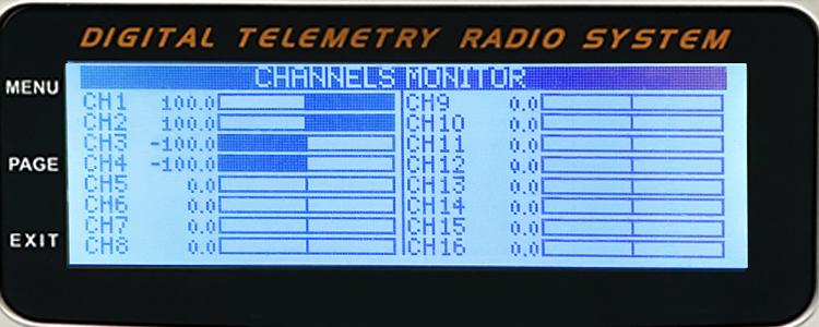
CH1 2000 µs (opentx +100), CH2 2000 µs (opentx +100)
CH3 1000 µs (opentx -100), CH4 1000 µs (opentx -100)
Chapter 7 Gyro Phase
Please refer to A560 RTF Chapter 7 Gyro Phase.
Chapter 8 Transmitter Setup
8.1 Model Type Setup
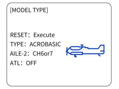
For A560 PNP version, model type needs to be set as fixed wing in the transmitter. Take AT9S Pro as example( same as AT10II/AT9S/AT10/AT9).
Steps: Power on the transmitter - Long press Mode to enter BASIC MENU - Turn the Dial to MODEL TYPE - Press Push to enter the menu and turn Dial to select ACROBASIC - Long press Push for 1 second and a notice “ARE YOU SURE”pops out - Press Push again and a notice”Please wait...” pops out and there will be DEE sound heard, meaning setting complete.
8.2 Transmitter Phase Setup
Please set the direction of CH3 to Reverse, and other channels CH1/CH2/CH4 to Normal. Take AT9S Pro as example( same as AT10II/AT9S/AT10/AT9).
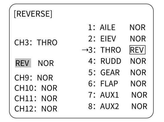 Steps: Long press Mode to enter BASIC MENU - rotate Dial to REVERSE - Press Push to enter the menu - rotate Dial to 3:THRO - change NOR to REV - Long press Push for 1 second to confirm.
8.3 Transmitter Phase Test
Please refer to A560 RTF Chapter 8.2 Transmitter Phase Test.
Technical Support Here


Contact RadioLink RL A560 User Manual A560 Tutorials
via Facebook Messenger
If the above information cannot solve your problem, you can also send emails to our technical support: after_service@radioLink.com.cn
This content is subject to change.
Download the latest manual of A560 from https://www.radiolink.com/a560_rtf_manual
Thank you again for choosing RadioLink product.