


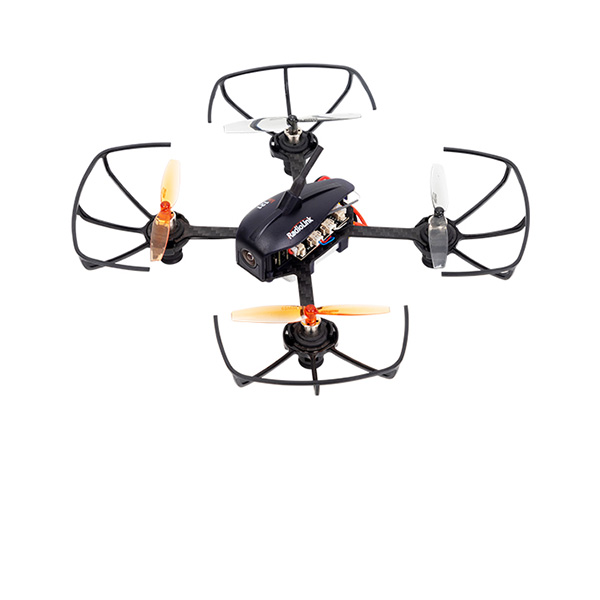
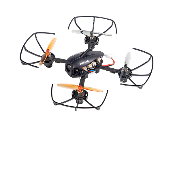
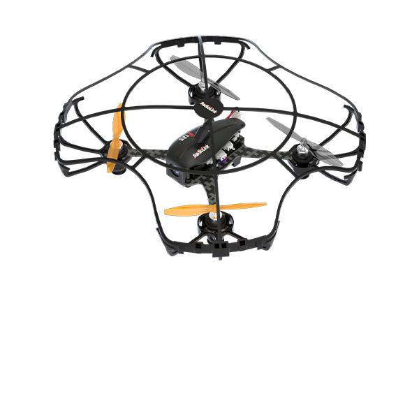


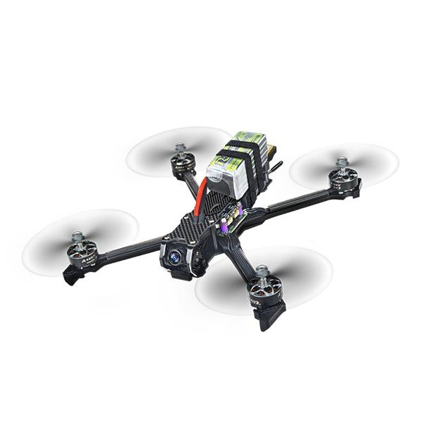
Wolf QAV250
Instruction Manual
* Please be kindly noted that this manual will be updated regularly and please visit RadioLink official website https://www.radiolink.com/qav250_manaul to download the latest version.
Disclaimer and Warning
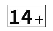
Thank you for purchasing RadioLink Wolf QAV250. To fully enjoy the benefits of this product and ensure safety, please read the manual carefully and set up the device as instructed steps. This product is not a toy and is NOT suitable for children under the age of 14. Adults should keep the product out of the reach of children and exercise caution when operating this product in the presence of children.
Inappropriate operation may causes property loss or accidental threats to life. Once the RadioLink product is operated, it means the operator understands this limitation of liability and accepts to take responsibility of the operation.
Make sure to follow the local laws and agree to follow the principles that made by RadioLink.
Fully understand that RadioLink cannot analyze the product damage or accident reason and cannot offer after-sales service if no flight record is provided. To the maximum extent permitted by law, RadioLink won't take any responsibility about the loss caused by indirect/consequent/accidental/special/penal damages including the loss by purchase, operation and failure of operation in any instances. Even RadioLink is informed about the possible loss in advance.
Laws in certain countries may prohibit the exemption from the terms of the guarantee. Therefore consumer rights in different countries may vary.
In compliance with laws and regulations, RadioLink reserves the right to interpret the above terms and conditions. RadioLink reserves the right to update, change or terminate these terms without prior notice.
SAFETY PRECAUTIONS
1. Please do not fly in the rain! Rain or moisture may cause flight instability or even loss of control. Never fly if there is lightning. It is recommended to fly in conditions with good weather (No rain, fog, lightning, wind).
2. When flying, you must strictly abide by local laws and regulations and fly safely! Do not fly in no-fly areas such as airports, military bases, etc.
3. Please fly in an open field away from crowds and buildings.
4. Do not perform any operation under the condition of drinking, fatigue or other poor mental state. Please operate in strict accordance with the product manual.
5. Please be cautious when flying near electromagnetic interference sources, including but not limited to: high-voltage power lines, high-voltage transmission stations, mobile phone base stations and TV broadcast signal towers. When flying in the above-mentioned places, the wireless transmission performance of the remote control may be affected by interference. If there is too much interference, the signal transmission of the remote control and the receiver may be interrupted, resulting in a crash.
6. Please be sure to install the propeller according to the instructions in the manual to avoid installing the reverse propellers and causing a crash.
7. When flying, please keep a certain distance from the aircraft and stay away from high-speed rotating parts (such as propellers, motors).
8. During flight or test-flight when the propeller is rotating, no matter what state the aircraft is in, never touch the aircraft with your hands or any part of your body. Please ensure your own personal safety.
9. After the flight, be sure the disarm is successful. Please unplug the battery until the propellers stops.
10. When connecting the flight controller to Mission Planner or calibrating the ESC, please make sure that the propellers are not installed on the aircraft.
11. When taking off, please turn on the transmitter first and then the aircraft; After finishing the flight, unplug the aircraft battery first and then power off the transmitter.
12. If you need to modify the aircraft parameters, please disassemble the propellers first and then adjust the parameters to ensure safety.
13. When arming with success, make sure to stay a certain distance away from the aircraft to ensure safety.
14. Gently push the throttle when start the flight: Under Alt-Hold mode, push the throttle a bit higher than the central point and Wolf QAV250 will slowly take off and keep rising if keep pushing the throttle. When Wolf QAV250 reaches a certain height, it will hover if stop pushing the throttle. Pilots can change directions by rolling, pitching and yawing.
15. It’s advised to be accompanied with experienced pilot for the first flight.
Chapter 1 Introduction
1.1 Feature Highlights
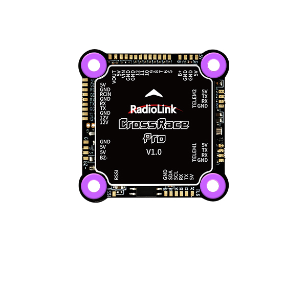
Wolf QAV250, with the flight controller CrossRace Pro, combines the high-precision PosHold Flight Mode of the autonomous flight controller APM(ArduPilot) and the professional manual control performance of Betaflight, achieving 180km/h even at the PosHold Flight Mode. It can brake and stop immediately, even in the high-speed flight state of professional manual mode. Wolf QAV250 is equipped with professional racing-level configuration, and the flight controller CrossRace Pro, with an OSD module integrated, can graphically display OSD information such as the flight direction and position of the aircraft in real time without the need for an external OSD module. By combining socket interfaces and soldering pads, it supports DJI O3 and CADDX Walksnail Avatar HD PRO KIT high-definition digital image transmission plug-and-play. Equipped with the high-precision GPS designed by Radiolink, Wolf QAV250 can automatically return home when the power battery voltage reaches the return voltage set or when it loses signal, allowing pilots to be worry-free about losing the aircraft when flying outdoors. Geofence can be set according to the drone management regulations promulgated by the country. In Manual Mode, no matter what attitude the aircraft is in, switching to PosHold Flight Mode, the drone will immediately keep hovering, which is a great help for racing drone freshmen in training. Through the natural progression of PosHold Flight Mode, Altitude Hold Mode, Stabilize Mode, and then Manual Mode, you can get started with FPV in just half a day.
1.2 About Wolf QAV250
The motor, propellers, battery, and ESC may be different. Please confirm the detailed parameters with the salesperson before purchasing. The actual accessories and packages are subject to the sales interface.
Wolf QAV250 Packing List |
|||||||
Name |
Details |
(HD Digital Video Transmission) |
(HD Digital Video Transmission with Monitor) |
(HD Digital Video Transmission with Goggles) |
(Analog Video Transmission) |
(Analog Video Transmission with Monitor) |
(Analog Video Transmission with Goggles) |
Frame |
Carbon Fiber Frame |
1 |
1 |
1 |
1 |
1 |
1 |
Transmitter |
RadioLink AT9S Pro |
1 |
1 |
1 |
1 |
||
Receiver |
RadioLink R12DSM |
1 |
1 |
1 |
1 |
||
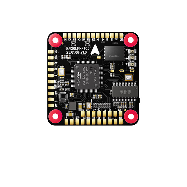
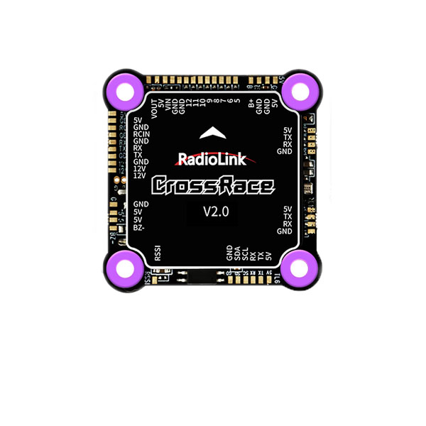
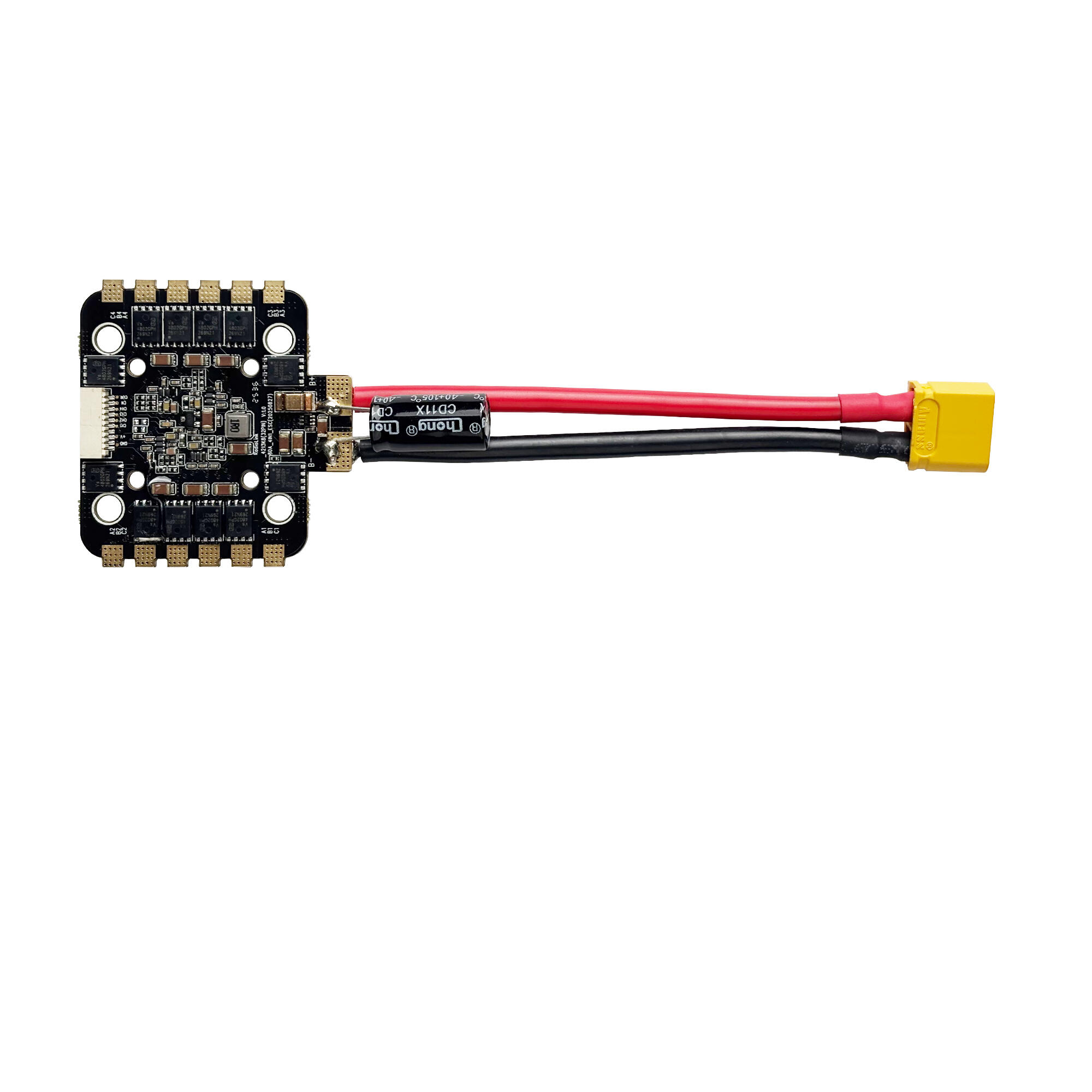
FC |
RadioLink CrossRace Pro |
1 |
1 |
1 |
1 |
1 |
1 |
GPS |
RadioLink TS100 |
1 |
1 |
1 |
1 |
1 |
1 |
Motor |
1950KV Brushless Motor |
4 |
4 |
4 |
4 |
4 |
4 |
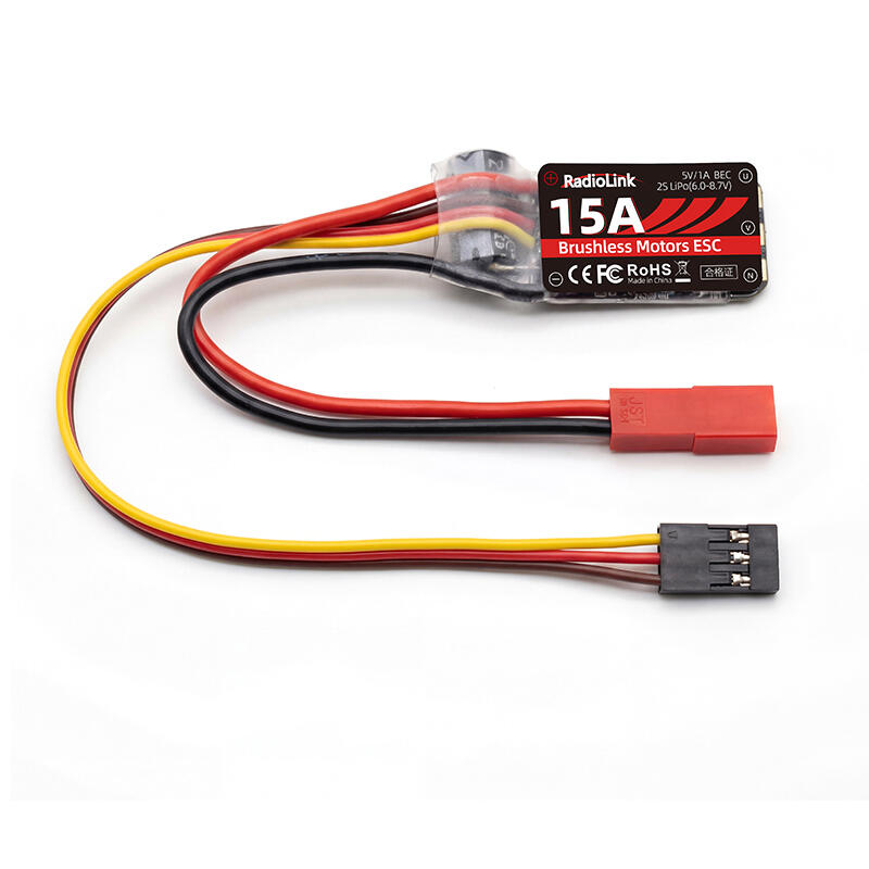
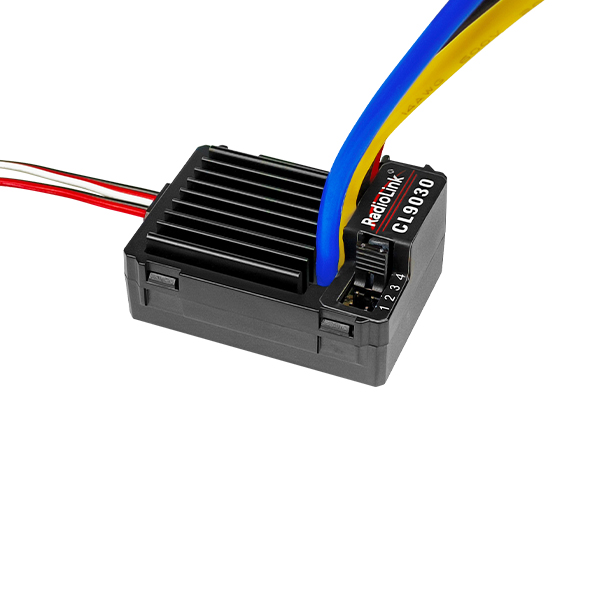
ESC |
55A ESC |
4 |
4 |
4 |
4 |
4 |
4 |
Propeller |
5" Propeller |
4 |
4 |
4 |
4 |
4 |
4 |
Battery |
6S XT60 Battery |
1 |
1 |
1 |
1 |
1 |
1 |
HD Digital Video Transmission |
Walksnail Avatar V2 Module |
1 |
1 |
1 |
|||
Walksnail Avatar FPV VRX |
1 |
||||||
Analog Video Transmission |
Video Transmission |
1 |
1 |
1 |
|||
Camera |
Walksnail Avatar HD pro Camera |
1 |
1 |
1 |
|||
sable Camera |
1 |
1 |
1 |
||||
Goggles |
Walksnail Avatar HD pro Goggles |
1 |
|||||
LONGSITE 3 inch FPV Goggles |
1 |
||||||
Monitor |
5-inch IPS FPV Monitor |
1 |
|||||
Hawk eye all-in-one 4.3 inch FPV Monitor |
1 |
||||||
Charger |
HOTA T6 Charger |
1 |
1 |
1 |
1 |
||
Screwdriver Socket Wrench |
Screwdriver Socket Wrench |
1 |
1 |
1 |
1 |
1 |
1 |
Hex Wrench |
2.0mm&1.5mm Hex Wrench |
2 |
2 |
2 |
2 |
2 |
2 |
Battery Strap |
FlyingFish Battery Strap |
2 |
2 |
2 |
2 |
2 |
2 |
Bag |
Portable Bag |
1 |
1 |
1 |
1 |
1 |
1 |
1.3 Specifications
Aircraft
Weight of Drone (Without Battery): 390g
Takeoff Weight Without Load: 615.5g
Dimension Frame: 222*204*39mm
Diagonal Length: 250mm
Material Frame: FlyFishRC Frame, carbon fiber
Flight Time: 15-minute without load
Flight Speed: 180km/h(Pos-Hold Mode)
Max Takeoff Altitude: 4000 meters
Max Tilt Angle: 30°/35°
Operating Temperature: -30℃~85℃
Flight Distance: 4000 meters, maximum range is tested in an unobstructed area free of interference
Max Service Ceiling Above Sea Level: Same as the flight distance, the flight distance and height can be set as you need in GeoFence of Mission Planner
Maximum Wind Resistance: Moderate breeze
Flight Modes: It is default with Stabilize Mode, Alt-Hold Mode, Pos-Hold Mode, and RTL, 13 modes can be set in the Mission Planner including Auto Mode, Guided Mode, flight follow the waypoint, etc.
Positional Accuracy: Up to 50 centimeters
Flight Control System: Radiolink CrossRace Pro, OSD integrated
Global Navigation Satellite System: TS100, BD1+GPS/L1+Galileo/E1+GLonass/G1, and quad satellite system operation at the same time are available.
Power System
Motor: 1950KV Motor
Electronic Speed Control (ESC): 55A Brushless ESC
Battery: 6S XT60 Battery
Propeller: 5" Propeller
Remote Control System
Transmitter: 12 channels transmitter AT9S Pro
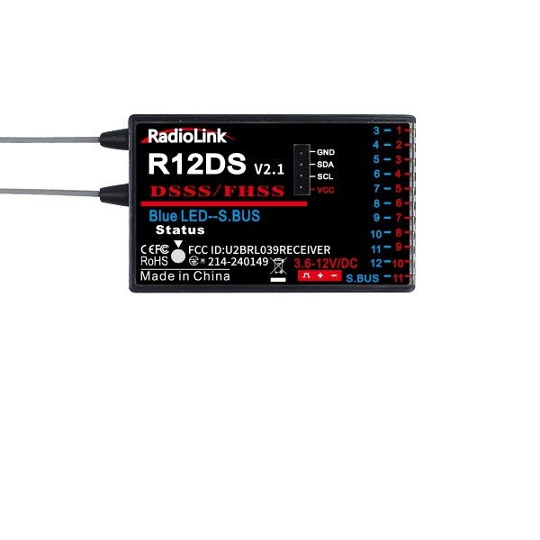
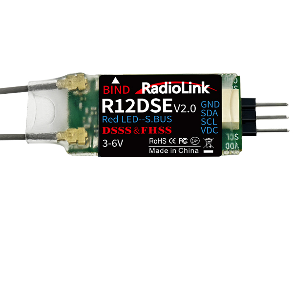
Receiver: R12DSM
Frequencies Band: 2.4GHz ISM(2400MHz~2483.5MHz)
Transmission Power: <100mW(20dbm)
Operating Temperature: -30° to 85° C (-4° to 185° F)
Control Distance: 4000 meters, maximum range is tested in an unobstructed area free of interference
Charger System
Charger: HOTA T6
Charging Input: DC 10-30V; PD 3.0/QC 20V
Charging Current: DC 15A; PD 5A
Compatible Battery: LiHV/LiPo/LiFe/Lilon/Lixx : 1~6S
NiZn/NiCd/NiMH : 1~14S
Smart Battery: 1~6S
Lead Acid(Pb): 1~12S(2~24V)
Eneloop: 1~14S
Power: 0.1~15A@300W;PD 90W
Power Supply: 0.1-15A@5-29V
Balance Current: 600mA
HD Digital Video Transmission
Video Transmission
Model: Avatar V2 module
Communication Frequency: 5.725-5.850GHz
Transmitter Power(EIRP): FCC:<30dBm; CE:<14dBm; SRRC:<20dBm; MIC:<25dBm
I/O Interface: JST1.0*4(power cable);JST0.8*6(USB)
Recording: 1080P/720P
Latency: Average delay 22ms
Average Gain: 1.9dBi
Transmission Distance: >4km
Channels: 8
Wide Power Input: 6-25.2V(2S-6S)
Storage: 8G/32G
Camera
Model: Avatar HD pro
Image Sensor: 1/1.8-Inch sony starvis2 sensor
Resolution: 1080P/60fps;720P/100fps;720P/60fps
Ratio: 4/3 16/9
Lens: 8Mp
FOV: 160°
Aperture: F1.6
Shutter: Rolling shutter
Min.Illumination: 0.0001Lux
Coaxial Cable: 140mm
Goggles(Can Be Selected))
Model: Avatar HD Goggles X
Communication Frequency: 5.725-5.850GHz
Transmitter Power(EIRP): FCC:<30dBm; CE:<14dBm; SRRC:<20dBm; MIC:<25dBm
I/O Interface: HDMI Out, HDMI Input, 5Pin 3.5mm Audio Port, DC5.5*2.1mm Port, Micro SD Card Slot
Transmission Resolution: 1080p 100fps, 1080p 60fps, 720p 100fps, 720p 60fps
Code Rate: Max 50 Mbps
Min. Latency: Average 22ms
Average Gain: 2dBi
Polarization: LHCP
Transmission Distance: >4km
Channels: 8
Screen Resolution: 1920*1080/100Hz
Screen Material: OLED
IPD Mechanical Range: 57mm-72mm
Adjustable Focus Range: +2.0 to-6.0 Diopter
FOV: 50°
Power Input: 7-26V(2S-6S)
SD Card: Support 256G
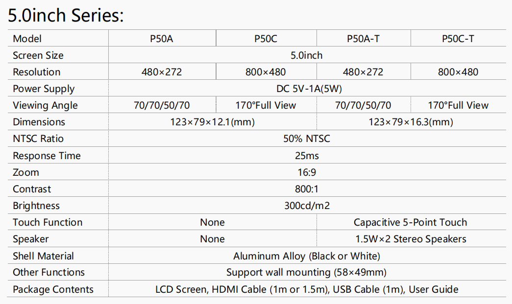
FPV Monitor(Can Be Selected)
Model: 5-inch IPS FPV Monitor
Dimension: 123*79mm
Resolution: 800*480
Color Space: 50% NTSC
Brightness: 300cd/m2
Interface: mini HDMI*1, micro USB*1
Note: This monitor does not come with image transmission receiver. It needs to be used with Walksnail AVATAR FPV VRX.
Analog Video Transmission
Video Transmission
Model: ZENCHANSI BROWN BEAR 008
Communication Frequency: 5.725-5.850GHz
Power: 0/25mW/200mW/600mW
Current(12V): 25mW(170mA)/200mW(230mA)/600mW(470mA)
Input Voltage: 7-24V DC
Antenna: MMCX ANT
Dimension: 27*27*4.8mm(1.06"*1.06"*0.19")
Camera
Model: Caddx sable camera
Sensor: 1/2.8” Inch Starlight Sensor
Resolution: 1200TVL
FOV: 130°(4:3) / 165°(16:9)
Image: 4:3 & 16:9(Switchable)
Min.Illumination: 0.001LUX
Wide Power Input: 4.5-36V
Working Temperature: -20°C ~ +60°C
Weight: 5.9g
Dimension: 19*19*20mm
Goggles(Can Be Selected)
Model: Mini FPV Goggles
Communication Frequency: 5.725-5.850GHz
Resolution: 480*320
Display Ratio: 16:9
Brightness: 350cd/m²
Video Delay: Video time-delay less than 20ms
Power Adapter: DC 5V/1A (USB interface)
Current: 360 ~ 400mA
Battery: 3.7V/1200mAh, each full charge revive around 2.5hr working time
FPV Monitor(Can Be Selected)
Model: Hawk eye all-in-one 4.3 inch FPV Monitor
Resolution: 480*3(RGB) *272
Backlight: LED
Brightness: 500 cd/m2
Aspect Ratio: 16:9
Response Time: 10ms
Color System: PAL/NTSC
Working Time: About 2 5 hours
Input Signal: Video (PAL/NTSC)
Output Signal: Video
Antenna Interface: RP-SMA
Sensitivity: -94db
1.4 Prepare Wolf QAV250
The assembly of Wolf QAV250 has already been completed when leaving the factory. You only need to install the propellers according to the instructions before flying. If the aircraft is left unused for a long time, it is strongly advisable to uninstall the propellers with the professional tool packed in the set and to (dis)charge the batteries to best storage status, that is, 3.8V per cell to avoid unexpected damage and to extend the product life span.
1.5 Prepare Transmitter
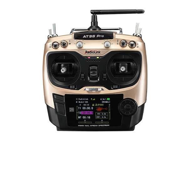
Wolf QAV250 PNP version is not equipped with a transmitter. You can optionally purchase a RadioLink transmitter to control Wolf QAV250, such as AT9S Pro.
If RadioLink transmitter is not equipped, please first install the receiver on the aircraft and bind your own transmitter and receiver after receiving Wolf QAV250. The detailed transmitter settings and radio calibration in Mission Planner depend on your transmitter, which will not be explained in detail in this manual.
Take AT9S Pro as an example. Before starting the flight, we need to power on the transmitter first to ensure that the transmitter works properly. AT9S Pro works with Lithium 2S-4S battery or 8 pieces AA battery. To avoid batteries over discharged, alarm of low voltage can be set after connecting batteries in the transmitter. Press “MODE”to enter the BASIC MENU => Select “PARAMETER”and enter=> Set“TX-ALARM”according to the actual battery used. For example, if batteries used in the transmitter is 2S, then it’s 4.2V*2S=8.4V when fully charged. As the voltage of a single cell is 3.7V, we usually set the low voltage alarm as 3.7V*2S=7.4V.
Chapter 2 Aircraft Setup
Wolf QAV250 consists of flight controller system, remote controller system, GPS system, power system, and image transmission system. This chapter is about the aircraft’s components and the feature of each function.
2.1 Setup for RTF and FPV Wolf QAV250
RadioLink Wolf QAV250 has 6 versions. (Please refer to Chapter 1.2)
If you have bought the version with RadioLink transmitter, you only need to power on the transmitter and the aircraft, and then arm the aircraft for flight.
2.1.1 Basic Operation of the Transmitter
As the aircraft is controlled to realize all movements by operating the remote controller, it’s important to know its basic operation.
Remote controller is also called transmitter and should work with a receiver. Transmitter in a pilot’s hand and receiver in an aircraft to work as the flight controller system.
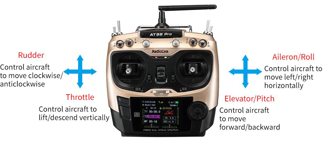
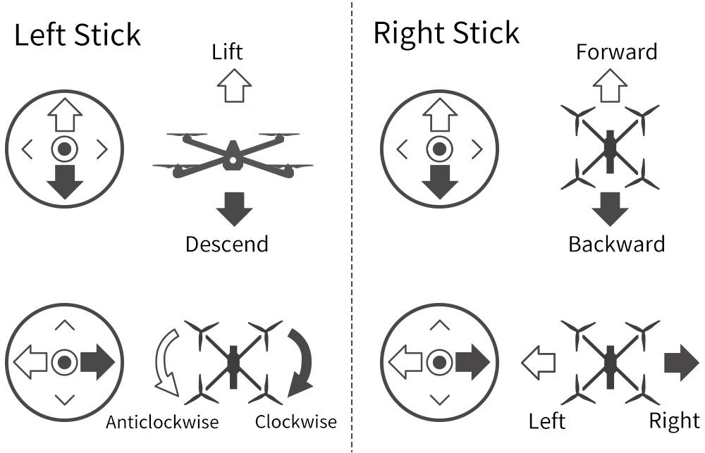
The 4 basic channels of all transmitters are always the same:
Channel (CH) |
Movement |
Channel 1 |
Roll (Control aircraft to move left/right horizontally) |
Channel 2 |
Pitch (Control aircraft to move forward/backward) |
Channel 3 |
Throttle (Control aircraft to lift and descend vertically) |
Channel 4 |
Rudder (Control aircraft to turn clockwise and anticlockwise) |
These four basic channels are operated by the two sticks on the transmitter. Most transmitters have not only these 4 channels but also other auxiliary channels such as switches for changing fight modes, controlling PTZ and camera. These commands will be passed to the receiver on aircraft via wireless signal by the emission system of transmitter. So we usually name the channels besides 4 basic ones auxiliary channels.
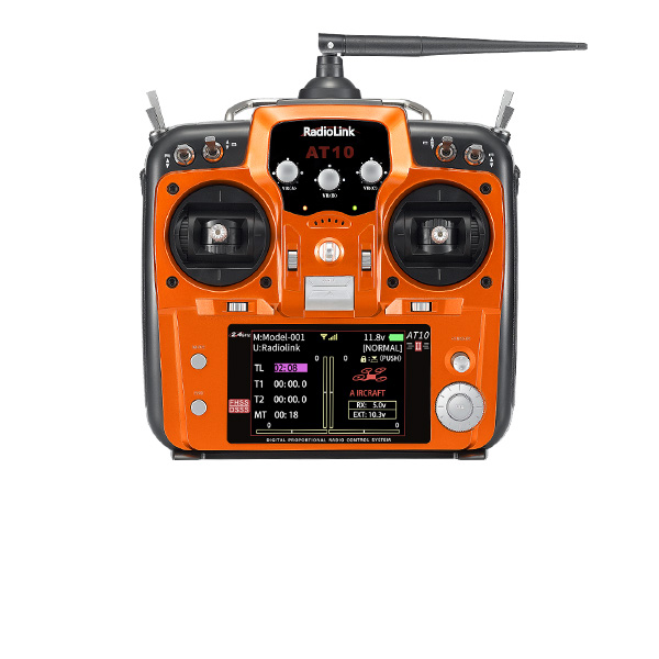
Here is a picture of transmitters with stick mode 2 (left throttle). Take RadioLink AT9S Pro transmitter as an example
For Wolf QAV250 that comes with AT9S Pro, auxiliary channel mapping has already been set on AT9S Pro. The specific mapping table is as follows:
Auxiliary Channel |
Function |
Switch |
Trigger Condition |
Channel 5 |
Flight Mode Switch |
SWC |
Push Up/Down |
Channel 6 |
Arm/Disarm |
SWA |
Push Up/Down |
Channel 7 |
Manual Mode |
SWB |
Push Up/Down |
Channel 8 |
RTL Mode |
SWD |
Push Up |
Channel 10 |
RSSI |
None |
None |
More details about AT9S Pro, please download the manual via the below link:
https://www.radiolink.com/at9spro_manual
2.1.2 Arm and Disarm Wolf QAV250
Arm: Channel 6 of the transmitter is assigned to control motor lock by default. If RadioLink transmitter is not equipped, please assign a two-way switch for channel 6. If AT9S Pro transmitter is equipped with Wolf QAV250, you can unlock/lock the motor with SWA switch. Push SWA up. If the indicator light of the flight controller is solid blue or green (Solid blue means the flight controller has been unlocked, but GPS positioning has not been performed; solid green means the flight control has been unlocked, and the GPS has been Positioning), and the motor and propellers start to spin slowly, the motor is unlocked.
Note:
Please ensure that the SWD is in the low position by default. If SWD is in the high position, it will automatically enter the RTL mode, which will result in the inability to arm.
When GPS positioning is not available, if the flight mode is Pos-Hold mode or loiter mode, which rely on GPS positioning, the arming will fail.
Please connect 6S lipo batteries to Wolf QAV250. Otherwise, the flight controller will issue a low-voltage alarm and fail to arm.
If the SWA is pushed up before the flight control self-test is completed, the aircraft will not be unlocked, but the motor lock will be removed. At this time, the flight controller indicator flashes blue. You can push SWA down and push it up again to unlock the motor.
Push SWA up. If the indicator light of the flight controller flashes yellow, there is some errors when arming. Please connect the flight controller to Mission Planner and make corrections according to the error prompts.
For more details, please refer to the detailed manual of CrossRace Pro: https://www.radiolink.com/crossracepro_manual
Disarm: Push down SWA, the motors and propellers will stop rotating immediately, and the flight controller indicator will turn yellow and flash, which means the motors are locked. This locking method can be used for emergency locking. In the event of an emergency, pushing down SWA can force the motor to stop rotating. If the aircraft is in the air, please use this function with caution to avoid property damage.
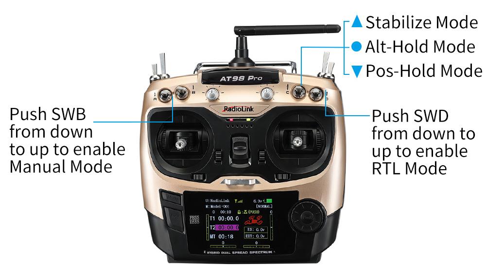
2.1.3 Flight Modes Introduction
Wolf QAV250 has five flight modes by default: Stabilize Mode, Alt-Hold Mode, Pos-Hold Mode, Manual mode and RTL Mode.
In Chapter 2.1.1 Basic Operation of the Transmitter, the functions of auxiliary channels were mentioned. One of those is to switch the flight mode.
For AT9S Pro, the 3-way switch (SWC on the right) by default, UP is Stabilize Mode, MID is Alt-Hold Mode, DWN is Pos-Hold Mode. Push SWB from down to up to enable Manual Mode. Push SWD from down to up to enable RTL Mode. For more flight modes, please refer to the manual of CrossRace Pro:
https://www.radiolink.com/crossracepro_manual
Note: The flight mode of the aircraft always remains the last selected flight mode. If you push SWB up first and then SWD, the aircraft is in RTL mode; If you push SWD up first and then SWB, the aircraft is in manual mode.
RTL Mode Enabled:
Besides manually enabled by pilots (SWD of AT9S Pro), RTL Mode of Wolf QAV250 can be automatically activated under the below two situations:
Signals lost.
Low voltage. Wolf QAV250 comes with a 6S lithium battery. RTL mode is enabled when the battery voltage is lower than 21V by default. You can modify it according to your own usage habits and flight plan. When the voltage is lower than 21V after a period of flight, the aircraft will automatically rise up to a certain height (15m by default) and then land on the point that it takes off. By the moment, Wolf QAV250 won’t move even if pilots toggle the transmitter sticks. Please arm the aircraft once landed and disconnect the battery and get it charged. If you need to operate the aircraft during the RTL process, you only need to switch the flight mode to another mode and then switch back to the original mode to exit the RTL mode.
After the aircraft returns to the take-off point, it will perform a landing operation. At this time, the pilot can fine-tune the position of the aircraft as needed to ensure that the aircraft lands at a suitable location.
2.1.4 Manual Mode of Wolf QAV250
Push SWB up to enable manual mode of Wolf QAV250. In this mode, the angle and speed restrictions of the flight controller will be completely released, and the flight attitude will be completely controlled manually. The aircraft will not automatically return to center after the joystick is returned to center in manual mode. Note: Pilots without manual mode flight experience are advised not to use this mode! In manual mode, the maximum flight speed can reach 180+km/h, please pay attention to flight safety.
2.2 PNP Version Setup
After receiving PNP version, the parameters of the aircraft have been set at the factory. PNP version does not come with a transmitter, so the pilot needs to set the transmitter.
Pilots who purchase PNP version of Wolf QAV250 need to: install Mission Planner to work with the flight controller, bind the transmitter and receiver and get the parameters set, and install the propellers.
Note: Wolf QAV250 PNP version is also compatible with the transmitter and receiver of the other brands. But please make sure that the receiver is SBUS/PPM/CRSF supported. When using a CRSF protocol receiver, please connect the receiver to TELEM1 or TELEM2 of CrossRace Pro. Please see Chapter 5.2.3 of the CrossRace Pro manual for details: https://www.radiolink.com/crossracepro_manual
2.2.1 Bind Transmitter to Wolf QAV250
Every transmitter owns a unique ID code. Before using, binding transmitter to receiver on aircraft is a must. When done binding, ID code will be stored in the receiver, no need to rebind.
If your transmitter has done binding with receiver, you only need to connect the receiver to the CrossRace Pro flight controller after receiving the PNP version of Wolf QAV250.
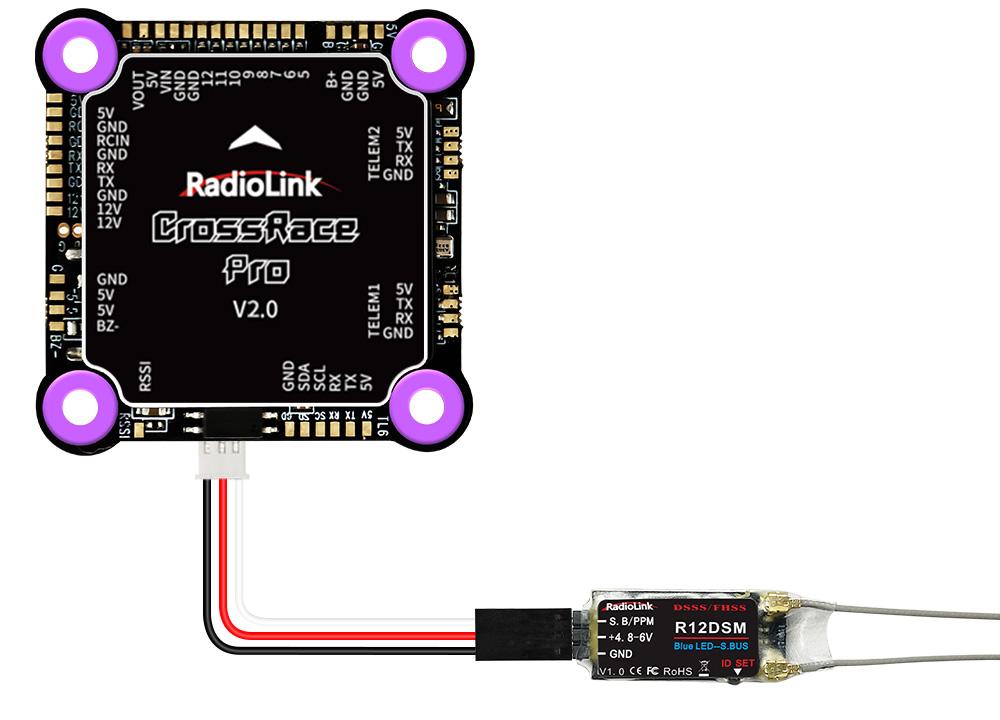
Connect RadioLink R12DSM receiver to CrossRace Pro
Binding the transmitter to the receiver is essential. Otherwise, the aircraft cannot take off.
Binding steps of all RadioLink transmitters and receivers are the same as follow:
Put the transmitter and the receiver together within 50 centimeters.
Power on the transmitter and the receiver. The receiver will bind to the closest transmitter.
Press the ID SET(binding button) on the side of the receiver for more than 1 second, the flashing LED means binding starts.
When LED stops flashing, binding is complete. A signal tower appears at the top of the home page of the AT9S Pro indicates successful binding. If there is no signal tower, please repeat the above binding steps.
When binding is done, please check if the receiver change to SBUS/PPM output . Generally we use SBUS signal. LED on all receivers from RadioLink is blue/purple means SBUS signal while red means PWM or PPM signal. Pilots can short press the binding button to switch the signals output of the receiver. For more details, please refer to the manual of RadioLink receivers (R12DSM manual: www.radiolink.com/r12dsm_manual). If receivers from other brands are used, please refer to their manuals.
2.2.2 Installation of Mission Planner
Before setting flight parameters, please install the Mission Planner for parameter adjustment of CrossRace Pro.
To run the Mission Planner installation, NET. Framework from Microsoft is needed. Link is as below
https://www.microsoft.com/net/download/thank-you/net462
Download link of CrossRace Pro Mission Planner:
https://www.radiolink.com/crossracepro_missionplanner
Mission Planner installation tutorial (Mini Pix is used as an example. The method is the same for CrossRace Pro):
https://www.youtube.com/watch?v=twW9CaRlj-U (Starting from 13:00)
2.2.3 Transmitter Parameters Setup
The flight controller of Wolf QAV250 has been set with all necessary parameters by default. For the PNP version, please calibrate the radio, set the flight modes and Fail Safe.
 2.2.3.1 Radio Calibration
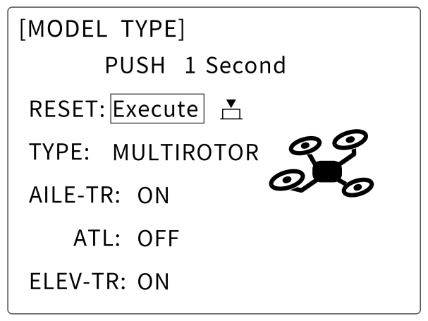
Before the radio calibration in Mission Planner, please make sure the model type selected in transmitter is multi-rotors. Below detailed steps take RadioLink AT9S Pro as an example. For the calibration of the transmitters from other brands, please kindly refer to the its instruction manual.
 Press“MODE”for more than 1 second to enter the BASIC MENU and choose“MODEL TYPE”, rotate the dial to select “MULTIROTOR”and press“PUSH”to save, then“END”to exit.
Note: For RadioLink transmitters, the throttle phase needs to be set REV. Throttle of AT9S Pro is set REV by default. Press“MODE”of AT9S Pro for 1 second to enter the BASIC MENU and choose“STEERING REVERSE”and select 3: THROTTLE. Then “PUSH”to select and rotate the dial to“REV”and“PUSH”to confirm then“END”to exit.
Make sure binding between the transmitter and the receiver is complete before connecting CrossRace Pro with Mission Planner on computer via USB cable with the Baud Rate of 115200. The connection between CrossRace Pro and Mission Planner can be also achieved by data transmission with the Baud Rate of 57600. Then power on the transmitter.
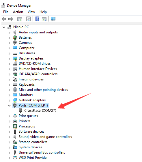
Open Mission Planner => select the corresponding Baud rate and port => click to connect
Note: Ports varies from different computers. Please select the correct port to connect. Connection may fail with several ports in use. Please remove the other connections, or enter Device Manager to view the port of CrossRace Pro, just as below:
 .
.
Click INITIAL SETUP =>MANDATORY HARDWARE => RADIO CALIBRATION =>CALIBRATE RADIO
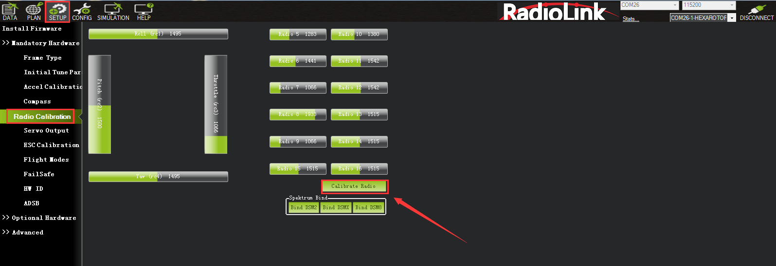
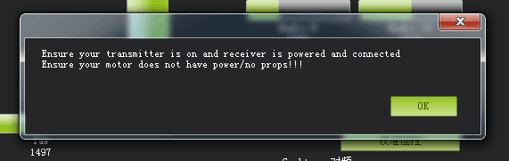
There are two tool pop-ups after you click “OK”, one for make sure both your transmitter and receiver are powered on and connected, and the motor of your drone does not have power and without propellers.
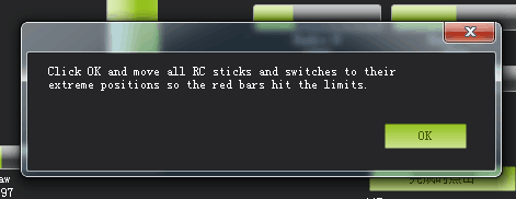
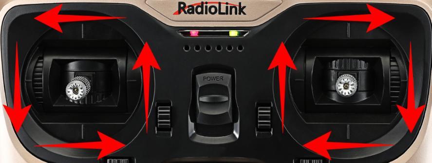
And then click“OK”and move all RC sticks and switches to their extreme positions so the red bars hit the limits.
Joysticks can be calibrated as following , both (CH1 to CH4) are pushed to the limits(up/down/left/right)
If the red bars have not any change when you move the sticks, please check the receiver have connect success or not, make sure the receiver (maybe R9DS) is output SBUS signal (the blue LED of R9DS means work as SBUS signal). You can check if every corresponding red bar for every channel is work as below:
CH1: low position = roll (towards the left), up position= roll (towards the right).
CH2: low position =pitch(forward), up position =pitch(backwards).
CH3: low position =reduced speed, up position =speed up.
CH4: low position = yaw (towards the left), up position = yaw (towards the right).
2.2.3.2 Flight Modes Setup
Set flight modes in the transmitter (refer to the following steps for RadioLink transmitters. When using transmitters from other brands, select channel 5 to set flight modes, and select the SBUS signal for the receiver. The settings of the flight controller in Mission Planner is the same as the following steps). QAV250 also uses channel 6 and channel 7 as two special flight mode selections. Please check the channel mapping table for more details.
CrossRace Pro has many flight modes, and you usually choose six. If the six are not enough, you can also add the assistance of CH7 and CH8, up to eight flight modes. But Wolf QAV250 is with five flight modes as factory setting by default including Stabilize Mode, Alt-Hold Mode, Pos-Hold Mode, Manual Mode and RTL Mode (See picture below). Therefore, if no other flight modes needed, pilots just set the flight modes in transmitter corresponding to those in flight controller.

Flight modes setting steps(Take AT9S Pro as an example):
1. Connect CrossRace Pro and receiver (connect the RC port of CrossRace Pro, and make sure receiver work as SBUS signal).
2. Make sure transmitter bind to receiver successfully.
3. Make sure CrossRace Pro connect to Mission Planner success and click INITIAL SETUP—Mandatory Hardware—Flight modes, you can setup the flight modes you want in this menu.
In flight modes menu, it’s very clear that the flight modes, the PWM numerical interval of six flight modes you have set and choose Simple Mode/Super Simple Mode or not.
Most of the RC fans setup the Flight Mode 1 is Stabilize, the other five flight mode will be setup according to users’ flight habit.
First, you have to setup flight mode in transmitter. The setting steps as below:
1. Power on and turn on your transmitter.
2. Press Mode button twice to into ADVANCE MENU, press Push button into ATTITUDE setting menu, CH5 is default to the attitude control channel and please choose a 3 Posi-SW and a 2 Posi-SW to control the attitude. (For the flight mode settings of CH7 and CH8, open Mission Planner--- configuration/debugging
---extended parameters---Channel 7 opt/Channel 8 opt, and then assign 2 control switches for the two channels in the transmitter. ) The attitude settings on AT9S Pro are as following:
3.Setup Flight Mode 1 is Stabilize both in Mission Planner and transmitter.
Make sure the -swt- is ON (by press the 3 Posi-SW or 2 Posi-SW to make it ON or OFF) and then you can setup the PWM data.
Setup the PWM value according to the default numerical interval (change the value by turn the dial, press the Push button when you choose the right value.)
4. Mode 4 needs a two-way switch. Turn the switch to the corresponding mode. Set it in the same way as step 3.
5. When using other transmitters to set flight modes, please first set the mixing control of channel 5. Mix a two-way switch and a three-way to channel 5, and set the value range according to the following chart:
Flight mode |
Value range(us) |
Flight mode 1 |
0-1230 |
Flight mode 2 |
1231-1360 |
Flight mode 3 |
1361-1490 |
Flight mode 4 |
1491-1620 |
Flight mode 5 |
1621-1749 |
Flight mode 6 |
1749+ |
For example, Wolf QAV250 has 3 flight modes by factory default. A three-way switch is assigned to control Channel 5. In Stabilize mode, We set the value range to 987 for Stabilize mode, between 0-1230, so Stabilize mode is flight mode 1; The value range is 1500 for Alt-Hold mode, between 1491-1620, so Alt-Hold mode is flight mode 4; The value range is 2000 for Pos-Hold mode, flight mode 6. Manual mode and RTL mode are activated by separate switches. Please check the channel mapping table for details. The order of flight modes can be modified according to your own flying habits.
Flight mode |
Value range (us) |
Stabilize mode |
987 |
Alt-Hold mode |
1500 |
Pos-Hold mode |
2000 |
2.2.3.3 Failsafe Setup
CrossRace Pro supports Return-To-Launch in cases where contact between the Pilot’s RC transmitter and the flight controller’s receiver is lost. This page explains this failsafe’s setup and testing. Note the“Radio failsafe”was previously called “Throttle failsafe” because of the way in which some receivers use the throttle channel to signal the loss of contact. Make sure the connection between the transmitter and receiver is successful and the receiver supports SBUS signal.
F/S setting steps:
Receiver and flight controller CrossRace Pro setup:
By default, a newly purchased receiver will be set-up to simply hold all channels at their last known position when the receiver and transmitter lose contact. This is not good because the flight controller has no way to know that the Pilot has lost control of the vehicle. Instead the receiver must be set-up to signal to the flight controller it has lost contact and there are two ways that it can do this (the method depends upon the receiver):
“Low-Throttle”method - the receiver pulls the throttle channel (normally channel 3) to a value below the bottom of its normal range (normally below 975).
With the LiPo battery disconnected:
1. Connect your flight controller to the mission planner and select Initial Setup >> Mandatory Hardware >> Failsafe.
2. Set the Failsafe Options to one of the three options:
(1) “Enabled always RTL” to force the vehicle to always RTL even if flying a mission in AUTO mode.
(2) “Enabled Continue with Mission in AUTO” to allow the vehicle to continue with missions even if it takes the vehicle outside of RC range (not recommended). In all other cases the vehicle will RTL.
(3) “Enable always LAND” to force the vehicle to Land immediately if it loses RC contact.
Set the “FS PWM” value to be:
(1) at least 10 PWM higher than your Channel 3’s PWM value when the throttle stick is fully down and the transmitter is off.
(2) at least 10 lower than your channel 3’s PWM value when the throttle stick is fully down and the transmitter is on.
(3) above 910.

Click OK to into the failsafe setting menu.
You can turn off transmitter to check if the Failsafe setup success(the PWM of CH3 is smaller than 975)
If enabled and set-up correctly the radio Failsafe will trigger if:
(1) The pilot turns off the RC transmitter.
(2) The vehicle travels outside of RC range.
(3) The receiver loses power (unlikely).
(4) The wires connecting the receiver to the flight controller are broken (unlikely).
1. Set battery fail safe
Set battery fail safe according to the aircraft power consumption, battery voltage, and flight distance. When the battery voltage is lower than this value, there will be enough battery voltage to return the aircraft. Set the low battery value (This value is set according to the battery voltage. When you fly long distances, Please set the single cell to 3.8V, the voltage value is 3.8V*S, the 6S battery is 3.8*6=22.8V; when at a close distance, you can set 3.6V for each cell), and set the action to RTL (return to home). RTL mode is enabled when the battery voltage is lower than 21V by default. You can modify it according to your needs.
The battery monitor has been calibrated at the factory. If the voltage measurement is inaccurate, please follow the steps below to re-calibrate it.
2. Set the radio fail safe (throttle fail safe). Set the action to RTL , and set the fail safe PWM (generally no need to change). Set the fail-safe setting in the transmitter, because we set the fail safe to start after the throttle is lower than 975, so we need to set the throttle fail safe value. Push the throttle trim button in the transmitter and check the input value of channel 3 in the transmitter in fail safe, so that the value is less than 10 or more than 975. Take RadioLink AT9S Pro as an example. Press the Mode button to enter the basic menu and select FAIL SAFE. Press Push to select Channel 3: Throttle. Turn the dial to select F/S and press Push button. When a value appears, the setting is successful. Remember to turn trim button to restore.
When a radio Failsafe is triggered one of the following will happen:
Nothing if the vehicle is already disarmed.
Motors will be immediately disarmed if the vehicle is landed OR in stabilize or acro mode and the pilot’s throttle is at zero.
Return-to-Launch (RTL) if the vehicle has a GPS lock and is more than 2 meters from the home position.
LAND if the vehicle has no GPS lock OR is within 2 meters of home OR the FS_THR_ENABLE parameter is set to “Enabled Always Land”
Continue the task if in automatic mode and the failsafe option is Enabled_continue_in_auto_mode.
If the failsafe is cleared (the throttle is above 975), the aircraft will continue to fly in the flight mode corresponding to the previously set failsafe, and will not automatically return to the previous flight mode of normal flight.
For example: the RTL mode is set for the fail safe, and the aircraft is flying normally in stabilize mode. Suddenly the fail safe is triggered due to signal loss, causing the aircraft's flight mode to automatically change from the stabilize mode to the previously set RTL mode. Even if the transmitter and receiver signals are reconnected during the return journey and the fail safe is released, the aircraft will still fly in the RTL mode. If you need to fly in stabilize mode again, you need to move the flight mode switch to another position and then back to the position of stabilize mode.
Set attitude fail safe in the transmitter. The prerequisite for setting attitude fail safe is that there is a fail safe mode in the flight mode settings. Taking RadioLink AT9S Pro as an example. Turn on the transmitter, flip the setting switch to RTL mode or the fail-safe mode you want to set, press Mode to enter the basic menu, select fail-safe, press Push to select 5: Attitude, Toggle to select F/S, hold Push, and the numbers below will change. Open Mission Planner to verify it. Turn off the transmitter and check that it is RTL in Mission Planner.
2.2.4 Propellers Installation
Wolf QAV250 PNP version is NO propellers installed for the package reason. So when the above steps are done setting(parameters set, ESC calibrated, arm successfully after powering on), propellers are ready to be installed. Make sure the correct installation of each positive/counter propeller. otherwise the aircraft may fail to take off.
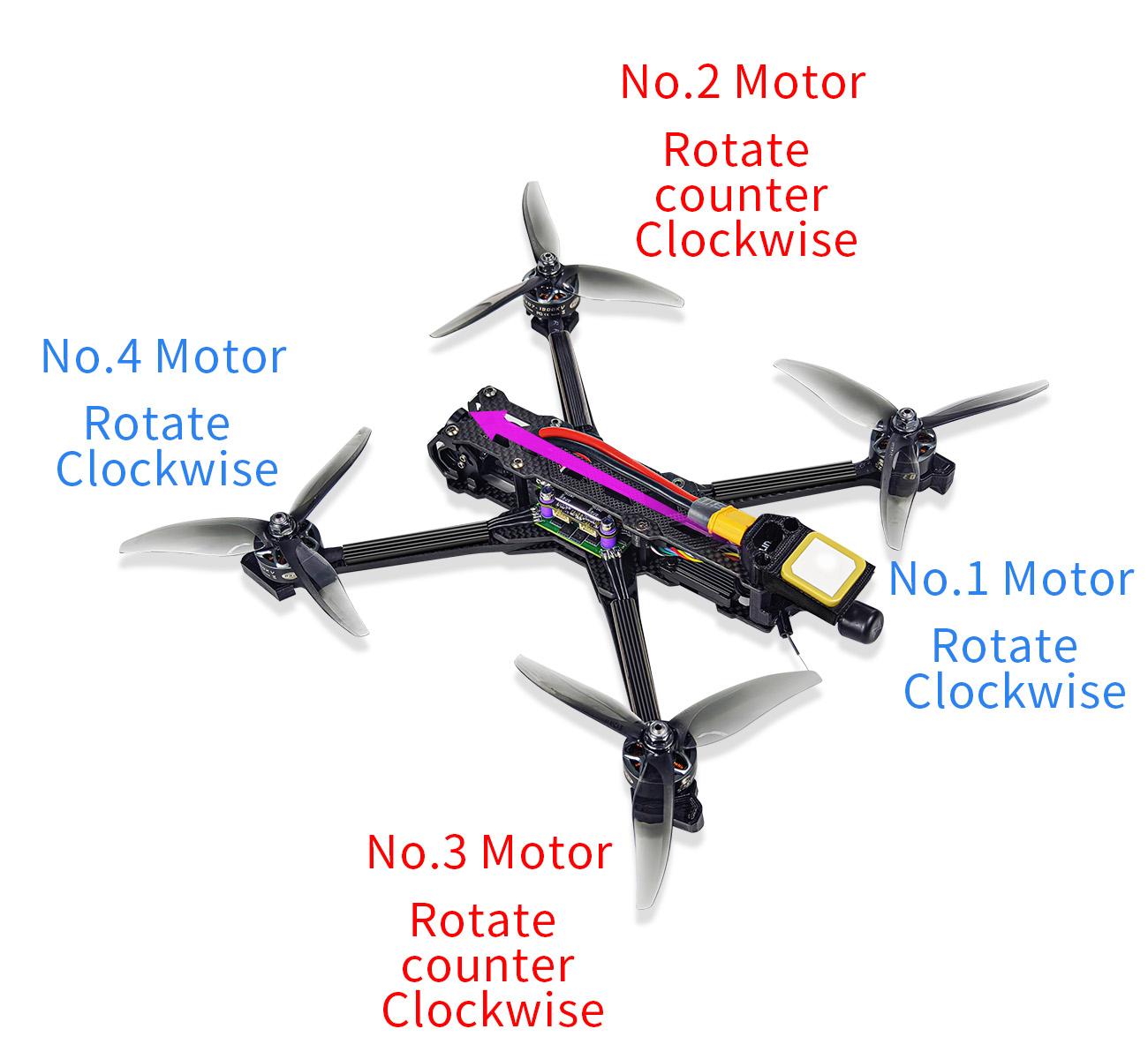
As the image shown below, put the head with camera forward when installing propellers and make sure propellers on Motor 2 and 3 rotate counter clockwise while that on Motor 1 and 4 rotate clockwise.
Note: Never install the propellers before finishing setting parameters of aircraft to ensure the safety.
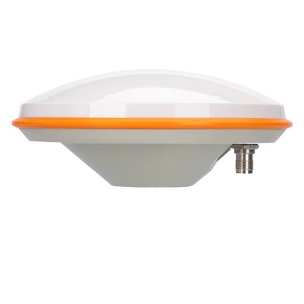
Wolf QAV250 is equipped with RadioLink MINI GPS TS100 as factory setting. If the Pos-Hold Mode and RTL Mode needed, please go to an open space and wait till the satellites searched to enjoy the flight.
Green indicator on GPS TS100 flashes means satellites searched. It’s advised to wait some time (about 1.5-2 minutes) for searching satellites at the first flight. And it will be a bit longer in cloudy weather. The quantity of the satellites searched reaches 18 or above will ensure the pos-hold and RTL accuracy.
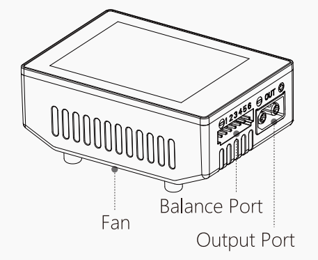
2.3 Charger
Wolf QAV250 can be equipped with HOTA T6 smart charger.
Specifications
Input Voltage |
DC 10~30V / PD 3.0/QC 20V |
Charge Current |
DC 15A / PD 5A |
Charge Power |
0.1~15A@300W |
Power Supply |
0.1-15A@5-29V |
PD 90W |
Discharge Current |
600mA |
|
Discharge Power |
Internal Discharge: 30W (Balance port 10W) |
Temperature |
-20~60°C |
External Discharge:700W |
Operating Temperature |
0~40°C |
|
Battery Type |
Lead Acid(Pb) : 1~12S(2~24V) Eneloop : 1~14S |
Screen Size |
260000 colors |
Dimensions |
70.5mm×49.5mmx30.5mm |
||
Net Weight |
93g |
||
Protection Function |
Temperature protection,time protection,capacity protection,input reverse protection,output protection,short circuit protection,output overcurrent protection,output overvoltage protection,overcharge protection |
Introduction
Warnings and Safety Notes
Do not use the charger in an unattended manner,in case of any functional abnormity,please stop using it and refer to the manual.
Keep the charger away from dust,humidity,rain and high temperature,as well as avoid direct exposure to sun and intense vibration.
Input voltage of the charger is 6.5-30V DC. When connecting the power supply, make sure that the input voltage match the operating voltage range of the charger.
Please place the charger on a heat-resisting,non-flammable and insulating surface. Do not use it by placing it on the car's seats,carpet or other similar place. Keep inflammable and explosive objects away from operation areas of the charger.
Make sure the heat emission hole at the side of the charger is uncovered while in use,and ensure the cooling fan smoothly extracts heat.
Please fully understand the charging and discharging characteristics as well as the battery's specifications. Additionally, set up proper charging parameters in the charger. Incorrect setting of parameters can cause damage to the charger and battery and/or result to disastrous consequences such as fire or explosion.
When charging or discharging is completed, please press the O key to terminate current task,and remove the battery when charger shows the standby screen.
Recommended Connected Way
Connect the power supply, wait for self-checking to be completed ;
Connect the battery to the charger under standby interface ;
Set up task parameters applicable to your battery through the display and touch key ;
 Enjoy.
Operative Skills
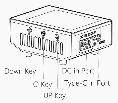
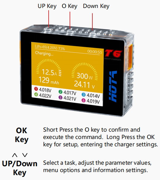
Connect power supply to the charger's PD or DC port, wait for the system to complete the self-checking. In standby interface, connect the battery to the charger. Short Press OK key to pop up the“Task Settings”menu, press the Up/Down key to select the operation task and adjust the task parameters, short press OK key to start the task.
When the task is being executed, you can short press the OK key to pop up the“ Adjust Task”menu to adjust the task's current or stop the task. long Press the OK key to quickly end the current task .
In standby interface, long press the OK key to enter the“Charger Settings”menu.
Charger Settings
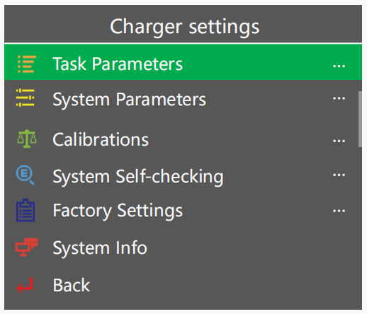
In the standby interface, long press the O key to pop up the“Charger Settings”menu. The menu items are as follows:
Task Parameters |
Adjust Safety Timer, Max Capacity, End Current and other parameters |
System Parameters |
Adjust Language, Regen. Discharge, input power, Volume and other parameters |
Calibrations |
For data calibration |
System Self-checking |
Start self-checking of the charger |
Factory Settings |
Restore all parameters to factory settings(User calibration data cleanup) |
System Info |
Display system information, serial number |
Back |
Exit “Charger Settings” |
For more details of the detailed operating instruction of HOTA T6 smart charger, please download it from the link: https://www.radiolink.com/manuals_download
Chapter 3 Flight
3.1 Visual Flight
At the beginning, it’s advised to flight visually by practicing basic movements like flying forward/backward/
leftward/rightward and hovering.
For example, beginners can try hovering under the stabilize mode by toggling the joysticks to adjust the aircraft to remain the same position. Then the horizontal 8 training for the next step.
3.2 FPV Flight
Different from visual flight, FPV is first person view with the help of a goggle or a screen. Theoretically, FPV flight is easier than visual flight because pilots can clearly judge the moment to turn or forward with goggle or screen.
Note: The image transmission, goggles and FPV monitors included in the FPV versions of Wolf QAV250 have already been linked by factory default and can be used directly without the need to link again. The following chapters are guides for using the image transmission, goggles and FPV monitors in the package for reference.
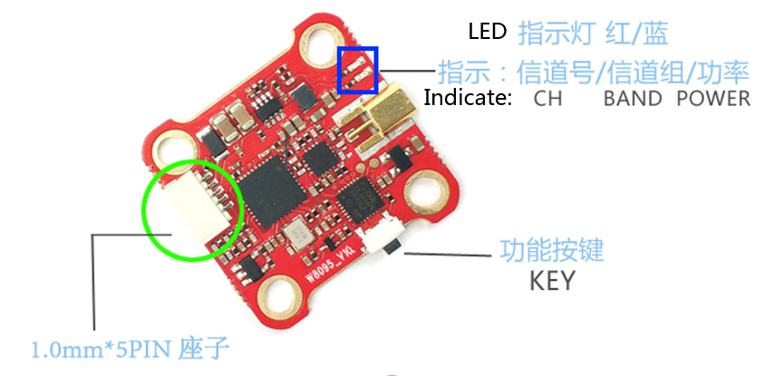
3.2.1 Walksnail AVATAR HD Pro Kit
The FPV RTF version of Wolf WAV250 (HD Digital Video Transmission Version) comes with Walksnail AVATAR HD Pro Kit.
Introduction
Connection

 Linking
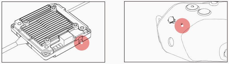
Connect the VTX and the power of the goggles.
Short press the VTX and goggles linking buttons respectively (as shown in the picture). When the VTX enters the pairing state, the indicator light turns red, and the goggles end is a DI…DI…DI …
After the link is successful, the indicator light on the VTX turns solid green, the beeping sound on the goggles stops and the screen is displayed.
Upgrade
Please go to the official website to download the upgrade firmware. Avatar_Sky_X.X.X.img is the VTX file. Copy to VTX U disk (VTX needs power supply), be careful not to change the file name.
Copy the upgrade file to the root directory of the VTX U disk, connect the power supply and wait for the device to start up (If there are old firmware files, please delete them).
Press and hold the VTX linking button for 8 seconds, and release the button after the indicator light goes out. At this time, the VTX will automatically restart and enter the upgrade state, and the indicator light will change from blinking red to solid red and then turn off. The upgrade time is about 20 seconds, please do not power off during the upgrade process! (If the VTX continues to light up red, it means that the firmware cannot be detected or the firmware is wrong, please check the firmware file).
After the upgrade is successful, the VTX indicator turns green and blinks.
Status indication
Goggles Buzzer Status |
|
Link state |
DI.…DI.…DI.… |
upgrade firmware |
D|……D|……DI……DI—— |
Upgrade failed |
DI..DI..DI.. |
VTX Indicator Status |
|
Link state |
Steady red light |
Upgrade firmware |
Red light rapidly flashes |
Wireless connection, image output is normal |
Steady green light |
Wireless not connected |
Green light rapidly flashes |
Wireless connection is normal, but the image is abnormal |
Green light slowly flashes |
Operating channel
Make sure you fully understand and abide by local laws and regulations before using this product. An amateur radio license may be needed in FCC regions when using channels 1, 2, 6 or 7, as they are amateur frequency bands. Users who use the amateur frequency bands with a modified or cracked version or without a license may be punished for breaking local laws or regulations.
Precautions
Before powering on, please install all antennas to avoid damage to components.
When the standby mode is turned on, the power is limited to 10mW. Before taking off, you need to unlock the flight control or turn off the standby mode.
If you use it with other 5.8GHz devices at the same time, please choose a different channel.
If you use the Gyroflow function of the camera, please provide shock absorption for the fixed deck of the camera to avoid the failure of the anti-shake.
VTX Specification
Model |
Avatar V2 module |
Communication Frequency |
5.725-5.850 GHz |
Transmitter Power (EIRP) |
FCC:<30dBm; CE:<14dBm; SRRC:<20dBm; MIC:<25dBm |
l/O Interface |
JST1.0*4(power cable) JST0.8*6(USB) |
Mounting Holes |
25.5*25.5mm; 20*20mm |
Dimensions |
33*33*10.5mm |
Storage |
8G/32G |
Recording |
1080p/720p |
Weight |
17.6g |
Operating Temperature |
-20-40℃ |
Channels |
8 |
Wide Power Input |
6V-25.2V |
Supported FC System |
Betaflight; Inav; Fettec; Kiss; ArduPilot |
OSD |
Canvas mode |
Latency |
Average delay 22ms |
Antenna |
1(IPEX) |
Camera parameters
Model |
Avatar HD pro camera |
Image Sensor |
1/1.8-Inch sony starvis2 sensor |
Resolution |
1080P/60fps; 720P/100fps; 720P/60fps |
Ratio |
4/3 16/9 |
|ens |
8Mp |
FOV |
160° |
Aperture |
F1.6 |
Shutter |
Rolling shutter |
Weight |
9.5g |
Dimensions |
19*19*24mm |
Min. Illumination |
0.0001Lux |
Coaxial Cable |
140mm |
VTX Antenna |
|
Model |
Avatar V2 antenna |
Polarization |
LHCP |
Frequency range |
5600MHz-6000MHz |
Average Gain |
1.9dBi |
VSWR |
<1.5 |
Interface |
IPEX-1 |
Dimension |
R15X45mm (without cable) |
Weight |
2g |
3.2.2 Walksnail AVATAR HD Goggles
 Introduction
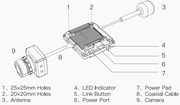
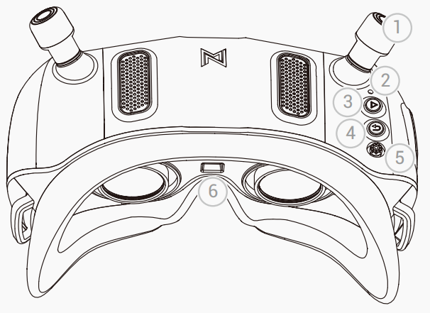
① Antenna
② Link Button (Short press to enter the linking state, long press for 8 seconds to enter the upgrade state)
③ Record Button (Press to start or stop video recording)
④ Back Button (Press to return to the previous menu or exit the current mode. Press and hold for 3 seconds to switch to CVBS and HDMI input mode, It can be switched cyclically)
⑤ 5D Button (Toggle the button to scroll through the menu. Press the button to confirm)
⑥ Proximity Sensor (Detects whether the user is wearing the goggles and automatically turns the screen on or off)
⑦ AV-IN Port (5 Pin 3.5mm Audio Port)
⑧ HDMI Input
⑨ Micro SD Card Slot
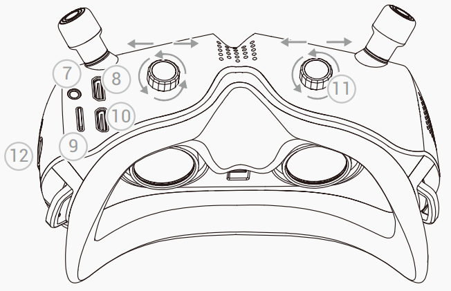
⑩ HDMI Output
⑪ IPD Adjusters (Adjust pupil distance and diopter)
⑫ Power Port (Voltage range 7V-26V, DC 5.5*2.1)
AV-IN Port Definition
1. GND
2. VCC (Goggles Battery Voltage)
3. RX
4. TX
5. CVBS (Connect to Analog Receiver Video Signal)
*When using the AV-IN port function, please connect the cable first, and then turn on the goggles.
Linking
Note: The VTX and Goggles have been linked by default for Wolf QAV250 FPV version. If the link fails, please refer to the following instructions to link them.
1. Connect the VTX and the power of the Goggles.
2. Press the link button of the VTX and Goggles respectively (as shown in the picture), when the VTX enters the pairing state, the indicator light turns red, and the Goggles end is a DI... DI... DI...
3. After the link is successful, the indicator light on the VTX turns solid green, the beeping sound on the Goggles stops and the screen is displayed.
Upgrade
Please go to the official website to download the upgrade firmware, AvatarX_Gnd_X.X.X.img is the Goggles file, copy it to the SD card, be careful not to change the file name.
1. Copy the upgrade file to the root directory of the SD card, connect to the power supply and wait for the device to initialize (delete the old firmware file first if there in one).
2. Press and hold the link button on the Goggles for 8 seconds, and the Goggles automatically restart and emit a beep...beep...beeper sound.
(Do not power off during the upgrade process, the upgrade time on the goggle is about 6 minutes)
3. After the upgrade is successful, and the beeping sound stops after the Goggles beeps for 5 seconds.
Status indication
Goggles Buzzer Status |
|
Link state |
DI.... DI.... DI.... DI.... |
Upgrade firmware |
DI...... DI...... DI...... DI—— |
Upgrade failed (No SD card or firmware detected) |
DI.. DI.. DI.. DI.. |
Boot failure (Reboot or re-upgrade) |
DI.. DI...... DI.. DI...... |
Operating channel
Make sure you fully understand and abide by local laws and regulations before using this product. An amateur radio license may be needed in FCC regions when using channels 1, 2, 6 or 7, as they are amateur frequency
bands. Users who use the amateur frequency bands with a modified or cracked version or without a license may be punished for breaking local laws or regulations.
Software interface
Main interface-1
VTX input voltage: Detect VTX voltage, intelligently identify the voltage of 2, 3, 4, 6 string LiPo batteries, alarm when a single battery is lower than 3.5V, and alarm in red font when the voltage is too low.
Goggles input voltage: Detect Goggles low battery alarm, intelligently identify the voltage of 2, 3, 4, 6 string LiPo batteries, alarm when a single battery is lower than 3.5V, red font and buzzer alarm when the voltage is too low.
Real-time bit rate: Display real-time transmission code rate, two display modes of 25.0Mbps and 50.0Mbps.
Time delay: Displays the total delay from the transmission of images captured by the VTX camera to the ground end.
Ranging mode: The function of calculating the transmission distance from Goggles to VTX according to the wireless transmission delay, the signal is interfered will lead to error amplification.
Status prompt: The text prompts information that needs attention in the current state.
Current channel: Display the current setting channel, the signal grid has 5 states, 4 grids, 3 grids, 2 grids, 1 grid, and blank.
Goggles SD card status: Display the status and remaining capacity of the Goggles SD card. When recording, the red circle flashes to prompt, the status of the SD card not detected is displayed as NO SD, and the status of the memory is full is displayed as -.
VTX storage status: Display the status and remaining capacity of the VTX storage, When recording, the red circle flashes to prompt, the status of the storage not detected is displayed as NO SD, and the status of the memory is full is displayed as -.
Menu Channel-2
Display the interference situation of each channel. The signal strength is divided into 4 grids, 3 grids, 2 grids, 1 grid, and a space. The signal display space is occupied and cannot be selected. The white stroke is the selection box. Press the middle button to confirm the current channel and highlight it.
Channel working logic: When switching between standard bit rate and high bit rate, the current channel will be set to CHP, and the channel needs to be reselected. CHP is a public channel, which is easy to be interfered and is not recommended for flight work; Auto is a channel that automatically refreshes the signal interference situation of all channels; Refresh is the channel of manual refresh.
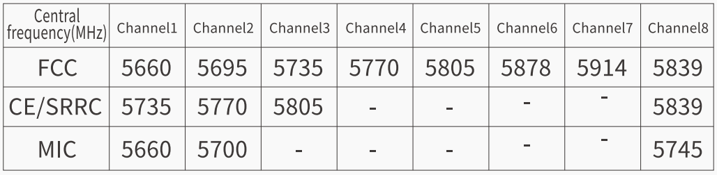
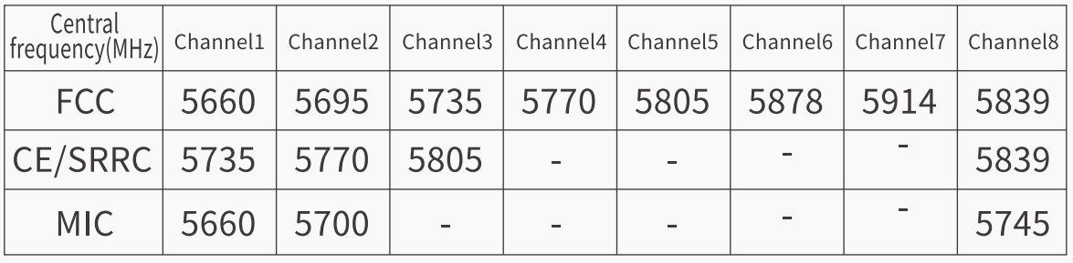
Channel display of each country: FCC standard displays 8 channels (CH1/2/3/4/5/6/7/P), CE/SRRC standard displays 4 channels (CH1/2/3/P), MIC standard displays 3 channels (CH1/2/P). Only in FCC mode, the high bit rate mode can be turned on, and the 8 channels become 4 channel s CH1, CH2, CH3, CHP.
Menu Settings-3
1-Camera:
The adjustable contents of the camera are scene preset, EV value, saturation, sharpness, white balance, rotate, ratio, 3D DNR, Shutter, and Max ISO settings.
2-Display:
Display adjustable content is zoom out, brightness, focalization mode, custom OSD, OSD position, font upgrade, custom font, viewfinder, viewfinder edit settings.
3-Record set:
The recording can be adjusted as VTX REC resolution, REC device, take off REC, REC loop, format SD card, format VTX, Built-in EIS, REC Time, REC Format, Color, Saturation, Sharpness.
4-Device:
The adjustable contents of the device are buzzer volume, Ranging mode, Weak signal, Reset all, Device information, Instruction, and Switch mode.
5-Transmit Power:
The default transmit power can be 25mW, 200mW, 500mW, 700mW.
6-Resolution:
The resolution can choose 720P and 1080P.
7-Bitrate:
Standard bit rate and high bit rate can be selected to obtain different image quality, and high bit rate can only be enabled in FCC mode.
8-Frame Rate:
Standard frame rate and high frame rate can be selected to obtain different time-lapse experiences.
9-Standby Mode:
When in standby mode, the transmission power of VTX terminal and Goggles terminal is 10dbm, and the current set transmission power will be output only after exiting standby mode or turning off the standby mode switch. Turning on the standby mode requires the air unit serial port to be correctly connected to the flight controller. When the goggles receive the drone’s unlock signal, it will automatically exit the standby mode. If there is no flight controller support, you can choose to turn off this function.
10-Language: Language switching English/中文.
11-Low Battery:
Detect Goggles low battery alarm, intelligently identify the voltage of 2, 3, 4, 6 string LiPo batteries, alarm when a single battery is lower than 3.5V, red font and buzzer alarm when the voltage is too low.
12-Goggle icon:
You can choose to display or hide the icons on the main menu interface.
13-Broadcast:
After turning on the broadcast switch, others can receive your video transmission through the Avatar system, The 6 characters in brackets are the unique identification number of VTX.
Menu Playback-4
The OSD switch can be turned on or off. When it is turned on, the flight control OSD information (if any) and the flight information of the main interface will be superimposed on the playing video interface. When the selection box stays in the video list, press and hold the VRX confirmation key to open the multi-selection function, and the menu box will display function settings (delete, select all, cancel), press the return key again to exit the multi-selection mode.
On the playback interface, click the middle button to pause/play, and the left and right arrow keys to adjust rewind/fast forward.
Precautions
1. This is a sophisticated product. Failure to operate this product in a safe and responsible manner could result in injury or damage to the product or other property. lt must be operated with caution and common sense and requires some basic mechanical knowledge.
2. Before powering on, please install all antennas to avoid damage to components.
3. When using HDMI output, Please make sure the monitor supports the set resolution and frame rate, otherwise it will cause abnormal display.
4. The transmit power of VTX and Goggles is only 10mW when the standby mode is on.
5. There are up to eight channels for the goggles depending on the region (FCC: eight, CE/SRRC: four, MIC: three). Each channel has a bandwidth of 20 MHz. The public channel is 8, which is the default channel when the equipment is powered on. The channel can be changed manually to avoid interference from other devices.
6. It is recommended to upgrade VTX and Goggles to the latest firmware before first use.
Specifications
Model |
Avatar HD Goggles X |
Communication Frequency |
5.725-5.850GHz |
Transmitter Power(EIRP) |
FCC:<30dBm; CE:<14dBm; SRRC:<20dBm; MIC:<25dBm |
I/O Interface |
HDMI Out, HDMI Input, 5Pin 3.5mm Audio Port, DC5.5*2.1mm Port, Micro SD Card Slot |
Transmission Resolution |
1080p 100fps, 1080p 60fps, 720p 100fps, 720p 60fps |
Code Rate |
Max 50 Mbps |
Min. Latency |
Average 22ms |
Average Gain |
2dBi |
Polarization |
LHCP |
Transmission Distance |
>4km |
Channel |
8 |
Screen Resolution |
1920*1080/100Hz |
Screen Material |
OLED |
IPD Mechanical Range |
54mm-74mm |
Adjustable Focus Range |
+2.0 to-6.0 Diopter |
FOV |
48° |
Power Input |
7-26V (2S-6S) |
SD card |
Support 256G |
System |
Avatar HD system |
WIFI |
|
Protocol |
IEEE 802.11b/g/n/ax |
Communication Frequency |
2.4GHz |
Transmitter Power (EIRP) |
<20dBm |
Bluetooth |
|
Protocol |
BLE 5.2 |
Transmitter Power (EIRP) |
<8dBm |
3.2.3 Walksnail AVATAR FPV VRX
Wolf QAV250 can be equipped with Walksnail AVATAR FPV VRX.
Introduction
Linking
Connect the VTX and the power of the VRX.
Press the link button of the VTX and VTX respectively (as shown in the picture), when the VTX enters the pairing state The indicator light turns red,and the VRX end is a DI...DI...DI..
After the link is successful, the indicator light on the VTX turns solid green, the beeping sound on the VRX stops and the screen is displayed.
Upgrade
Please go to the Walksnail offcial website to download the upgrade frmware. AvatarSE_Gnd_X.X.X.img is the VRX file, copy it to the SD card, be careful not to change the file name.
Copy the upgrade file to the root directory of the SD card, connect to the power supply and wait for the device to initialize (delete the old firmware file first if there in one).
Press and hold the link button on the VRX for 8 seconds, and the goggles automatically restart and emit a beep...beep...beeper sound.(Do not power off during the upgrade process, the upgrade time on the goggle is about 6 minutes)
After the upgrade is successful, and the beeping sound stops after the VRX beeps for 5 seconds.
Status indication
VRX Buzzer Status |
|
Link state |
DI....DI....DI.... |
Upgrade firmware |
DI......DI.....DI.....DI—— |
Upgrade failed (No SD card or firmware detected) |
DI..DI..DI.. |
Boot failure (Reboot or re-upgrade) |
DI..DI....DI..DI.... |
Operating channel

Make sure you fully understand and abide by local laws and regulations before using this product. An amateur radio license may be needed in FCC regions when using channels 1, 2, 6 or 7, as they are amateur frequency bands. Users who use the amateur frequency bands with a modified or cracked version or without a license may be punished for breaking local laws or regulations.
Button operation
Precautions
Before powering on, please install all antennas to avoid damage to components.
Please make sure the monitor supports the set resolution and frame rate, otherwise it will cause abnormal display.
The transmit power of VTX and VRX is only 10mW when the standby mode is on.
If you use it with other 5.8G devices at the same time, please choose a different channel.
Specifications
3.2.4 Portable Monitor
Wolf QAV250 can be equipped with 5.0 inch portable monitor.
Interface and functionality
Precautions
※ In order to ensure that the product can be used normally under reasonable conditions, please read the precautions carefully before use, and strictly abide by it.
If the monitor does not have a touch function, do not touch the screen with your fingers, as skin oils are difficult to wipe off.
Do not repair, disassemble or modify the monitor. There are high voltage parts inside the monitor, you may be seriously injured if you touch these parts.
The monitor is not waterproof, please do not soak it in water, water it or touch it with wet hands to prevent the monitor from being damaged by water or electric shock.
Do not insert conductive objects such as metal into the body or exposed interfaces to prevent damage to the monitor or electric shock.
Do not use the monitor in a high temperature place such as a car under the scorching sun or beside a heater to prevent damage.
Do not damage or process the display cable, do not get close to the heat source, do not forcibly twist, bend or pull the wire, and do not place or bundle heavy objects on the wire.
Do not repair, disassemble or modify the USB cable. If the cable is damaged, please replace the cable with the same specification to prevent electric shock or fire.
※ If the USB plug and USB cable become abnormally hot during use, please stop using it immediately if there is smoke or odor.
Parameters
Note: The monitor comes with QAV250 FPV version is P50C.
For more details of the 5.0 inch portable monitor, please download its detailed manual from the RadioLink official website: https://www.radiolink.com/manuals_download
3.2.5 ZENCHANSI 600mW Analog Video Transmission
The FPV RTF version of Wolf WAV250 (Analog Video Transmission Version) comes with ZENCHANSI 600mW analog video transmission and CADDX stable camera.
Introduction
LED indication
The red LED indicates the state of working mode or the item when setting the VTX (flashing 1 time means selecting the channels, flashing 2 times means selecting the bands, flashing 3 times means selecting the power levels).
The blue LED indicates the state of Pitmode or the value of item when setting the VTX (e.g. when selecting the channels, 3 times of flashing means channel 3. When selecting the bands, 3 times of flashing means band C.As for the item of power levels,3 times of flashing means at the power level of 600mW).
Working mode indication
After powering up, the red & blue LEDs will signal the following three items of VTX in turn: channel, band and power level(the flashing times of the red and blue LEDs indicate the item and the value respectively).
After that, the LEDs indicate the working modes.
Normal: The red & blue LED are on.
Pitmode: the Red and Blue LEDs will be twinkles .
KEY Setting
Setting of channel, band and power
After powering up, the flashing times of the red and blue LEDs indicate the item and the value respectively.
Press and hold the button until the red LED flash 1 time which means the item of channel selecting, then press the button can select the channels (blue LED flashing times corresponds to the channel 1-8).
Press and hold the button again, the red LED will flash 2 times which means the item of band selecting, then press the button can select the band (blue LED flashing times corresponds to the band A-R).
Press and hold the button again, the red LED will flash 3 times which means the item of power level selecting, then press the button can select the power (blue LED flashing times corresponds to the power level).
Finally, press and hold the button, save and exit the setting of VTX (This step is essential for setting).
Pitmode setting
Press the button twice will toggle the ON/OFF of Pitmode.
ZENCHANSI 600mW analog video transmission Frequency
Note
Make sure that there is enough space for airflow when installing the module on the drone in case the overheating protection starts to reduce the power even to shut down at the worst.
Please install the antenna before powering up for a longer use life.
Specifications
Model: Brown bear 008
Frequency: 5.8G 48CH
Transmitting Power:25mW/200mW/600mW/OFF(Pitmode)
Power supply:DC7V-24V
Current(12v):170mA(25mW)/230mA(200mW)/470mA(600mW)
Weight: 3.3g
Standard size:27*27*4.8mm
3.2.6 LONGSITE 3 inch FPV Goggles
Wolf QAV250 can be equipped with LONGSITE 3 inch FPV goggles.
Introduction
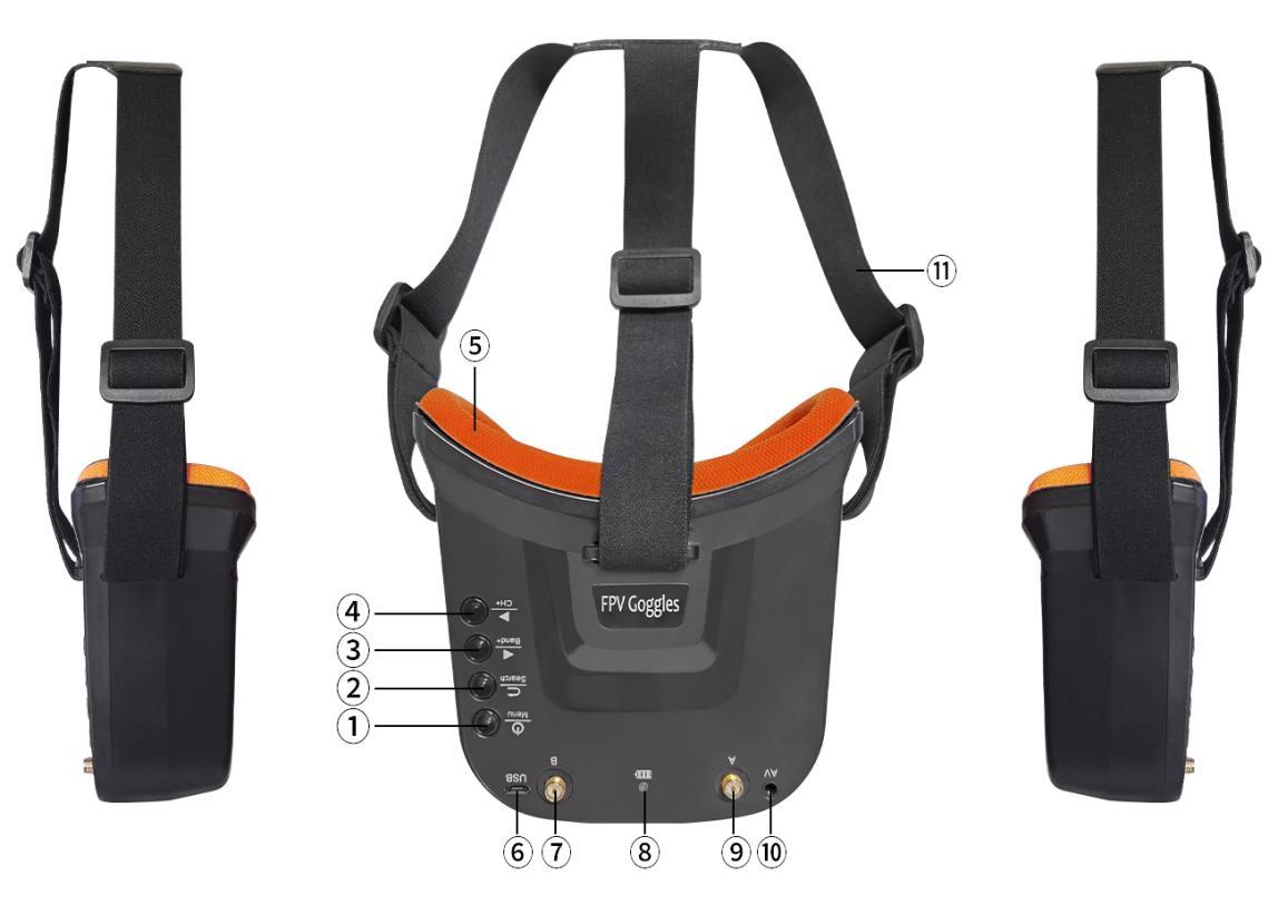
① Key 1: Short press for MENU mode; Long press (More than 3 sec) for Power ON/OFF.
② Key 2: Short press for Auto-Searching (Automatic selection of the strongest channel).
③ Key 3: Short press for Band+ (Change bands A-B-E-F-R circularly).
④ Key 4: Short press for Channel+ (Change channels 1-2-3-4-5-6-7-8 circularly).
⑤ Eye ring: protect the surrounding parts of the eyes, so that the wear more comfortable.
⑥ Micro-USB Charging port: Supports DC5V only.
⑦ Antenna port A: RP-SMA male.
⑧ Charging indicator: Red light when charging light; full power, the indicator goes off.
⑨ Antenna port B: RP-SMA male.
⑩ AV Jack: In RF receiving mode can output AV signal; In AV mode can enter the video signal.
⑪ Head band: Adjustable headband.
Menu operation instruction
In normal mode, press Key 1 to enter the MENU mode.
In MENU mode:
① Key 1: Select the option bar.
② Key 2: Return to normal mode.
③ Key 3: Value -.
④ Key 4: Value +.
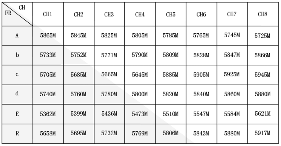
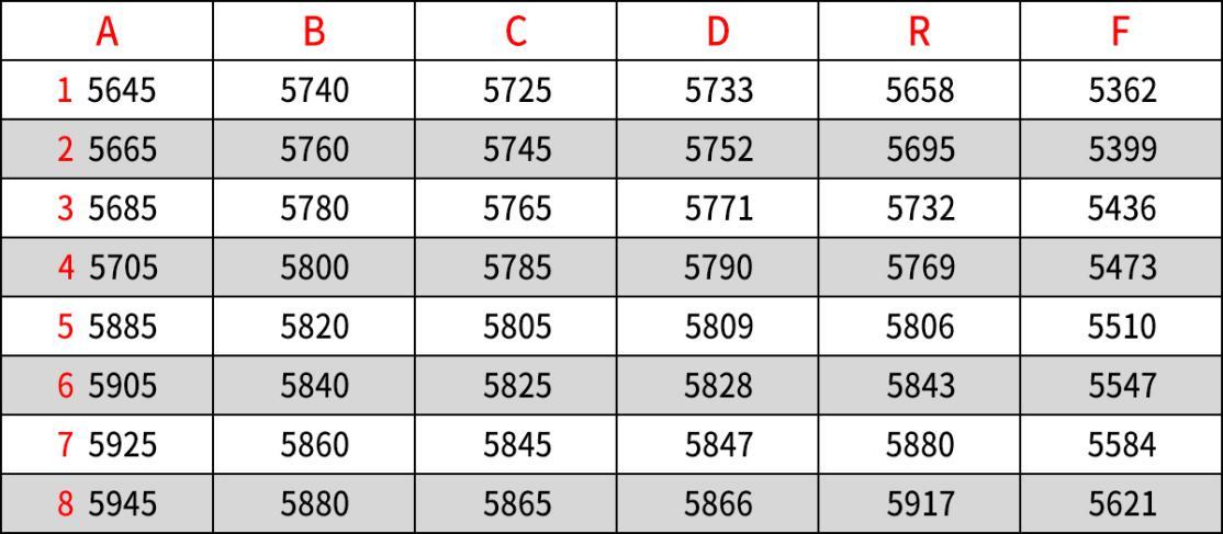
LONGSITE FPV goggles frequency table
Frequency Table(MHz) |
||||||||
CH1 |
CH2 |
CH3 |
CH4 |
CH5 |
CH6 |
CH7 |
CH8 |
|
Band A |
5865 |
5845 |
5825 |
5805 |
5785 |
5765 |
5745 |
5725 |
Band B |
5733 |
5752 |
5771 |
5790 |
5809 |
5828 |
5847 |
5866 |
Band E |
5705 |
5685 |
5665 |
5645 |
5885 |
5905 |
5925 |
5945 |
Band F |
5740 |
5760 |
5780 |
5800 |
5820 |
5840 |
5860 |
5880 |
Band R |
5658 |
5695 |
5732 |
5769 |
5806 |
5843 |
5880 |
5917 |
Specifications
Name: Mini FPV Goggles
LCD Screen size: 3.0 Inch
Resolution: 480*320
Display Ratio: 16:9
View Angle: 6 o'clock
Brightness: 350cd/m² with high brightness backlight LED
Video delay: less than 20ms
Lens: 4X Fresnel Lens, 92% transparent rate no distort of light
Antenna: 2 X RP-SMA male
Languages: English and Chinese
Power adapter: DC5V/1A (USB interface)
Battery: 3.7V/1200mAh, Each full charge revive around 2.5hr working time
3.2.7 Little Pilot (SCHOOL) 4.3 inch FPV Monitor
Wolf QAV250 can be equipped with Little Pilot (SCHOOL) 4.3 inch FPV monitor.
 Buttons and functions
Button Name |
Function |
1. Adjustment button(+) |
Short press to select desired frequency from 6 groups A-B-C-D-R-F |
2. Power/Menu button |
Long press to turn-on/off |
3. Adjustment button(-) |
Short press to select desired frequency from groups 1 - 2 - 3 - 4 - 5 - 6 - 7 - 8 |
4. Micro USB Charge port |
Charging |
5. Reset |
Reset |
Little Pilot monitor frequency group selection
Specifications
LED Screen |
Resolution |
480×3(RGB) ×272 |
Backlight |
LED |
|
Brightness |
250 cd/m2 |
|
Aspect ratio |
16:09 |
|
Response time |
10ms |
|
Color system |
PAL/NTSC |
|
Battery |
Battery life |
1 hour and 40 minutes |
Input |
Signal |
Video (PAL/NTSC) |
Output |
Signal |
Video (PAL/NTSC) |
Specification |
Monitor size |
113.5mm*79mm*14mm |
Gross weight |
130g |
|
5.8G sensitivity |
-94 dB |
Thank you again for choosing RadioLink product.