


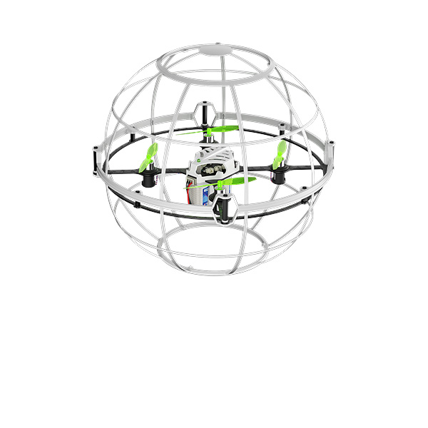


WOLF QAV210
High Speed Aerial Videography Racing Drone
Instruction Manual
Radiolink Electronic Ltd
* Please be kindly noted that this manual will be updated regularly and please visit Radiolink official website to download the latest version.
Thanks for purchasing Radiolink WOLF QAV210.
To fully enjoy the benefits of this product and ensure safety, please read the introduction carefully and set up the device as described below:
If any problems found during the operation process, please kindly refer to the manual first. Then pilots could contact our distributors to find solution or follow our Facebook homepage to search related key words. Also pilots can send questions to after_service@radiolink.com.cnafter_service1@radiolink.com.cn or after_service@radiolink.com.cnafter_service1@radiolink.com.cn and we will answer your question at the earliest.
Due to unforeseen changes in production procedures, the information contained in this manual is subject to change without notice.
For more information please check our website http://www.radiolink.com and follow our Facebook and YouTube homepage.
SAFETY PRECAUTIONS
Never operate models during adverse weather conditions. Poor visibility can cause disorientation and loss of control of pilots model.
Never use this product in a crowd or illegal areas.
Make sure no props installed when setting parameters of Mini Pix (the flight controller) on Mission Planner (MP) or calibrating ESC.
Always ensure the trim levers at 0 and battery properly charged before connecting the receiver.
Always check all servos and their connections prior to each run.
Stay at a certain distance from the aircraft during flight to avoid getting hurt by the components of high-speed rotation (eg. Props, brushless motors)
After landing off, make sure the aircraft is disarmed and props have stopped moving before getting close to touch the aircraft.
Always be sure about turning off the receiver before the transmitter.
When removing battery, NEVER pull the wires but please do press the yellow port with one hand and pull the other yellow port with another. If the wrapping materials damaged , the bare wires may cause DANGER.
Follow the instructions of props installation in case of dropping during flight.
To ensure the best radio communication, please enjoy the flight at the space without interference such as high voltage cable, communication base station or launching tower.
WARNING
This product is not a toy and is NOT suitable for children under the age of 18. Adults should keep the product out of the reach of children and exercise caution when operating this product in the presence of children.
Water or moisture may enter the transmitter inside through gaps in the antenna or joystick and cause model instability, even out of control. If running in the wet weather(such as game) is inevitable, always use plastic bags or waterproof cloth to cover the transmitter.
Set includes:
Name |
QAV210 Standard |
Qty |
QAV210 Advanced |
Qty |
Main Plate |
Carbon Fiber frame |
1 |
Carbon Fiber frame |
1 |
Radio |
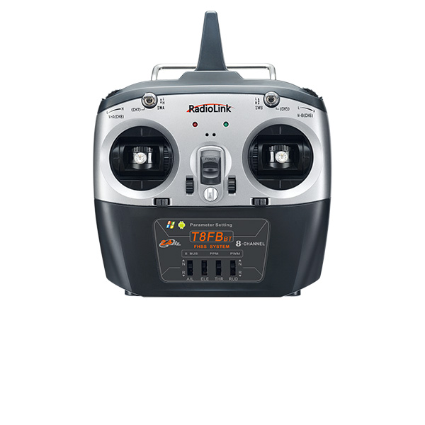
Radiolink T8FB 8CH |
1 |
Radiolink AT9S 10CH |
1 |
Reciver |
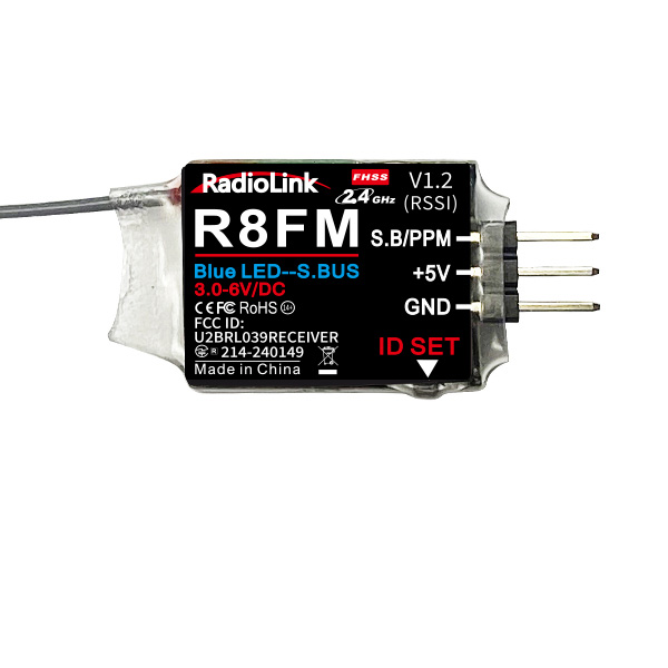
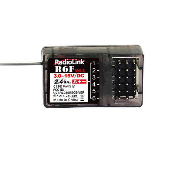
Radiolink R8FM |
1 |
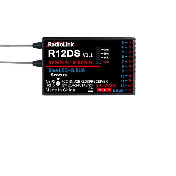
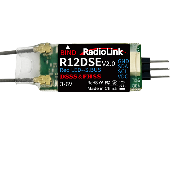
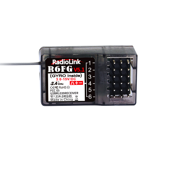
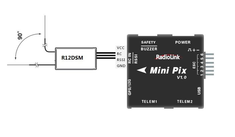
Radiolink R12DSM |
1 |
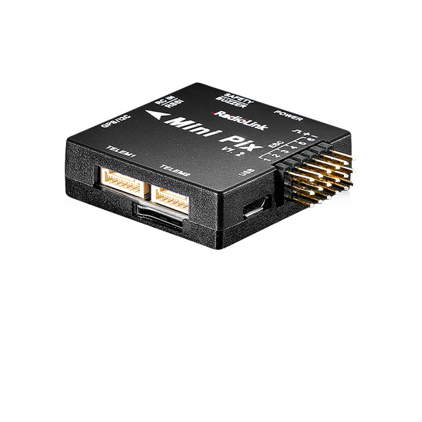
FC |
Radiolink Mini Pix |
1 |
Radiolink Mini Pix |
1 |
GPS |
Radiolink M8N GPS TS100 |
1 |
Radiolink M8N GPS TS100 |
1 |
Motor |
SZ-SPEED 2000KV |
4 |
SZ-SPEED 2000KV |
4 |
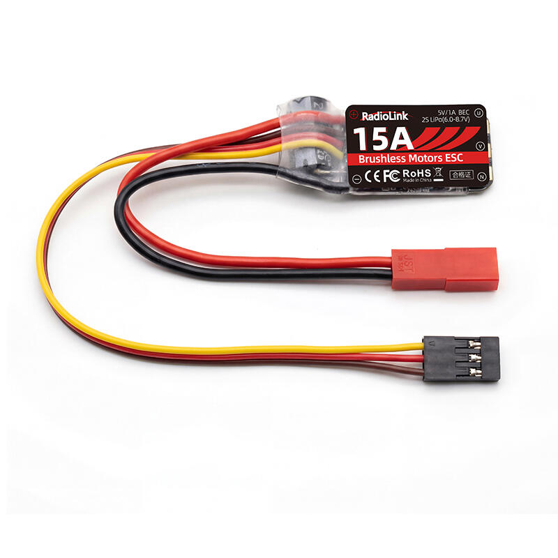
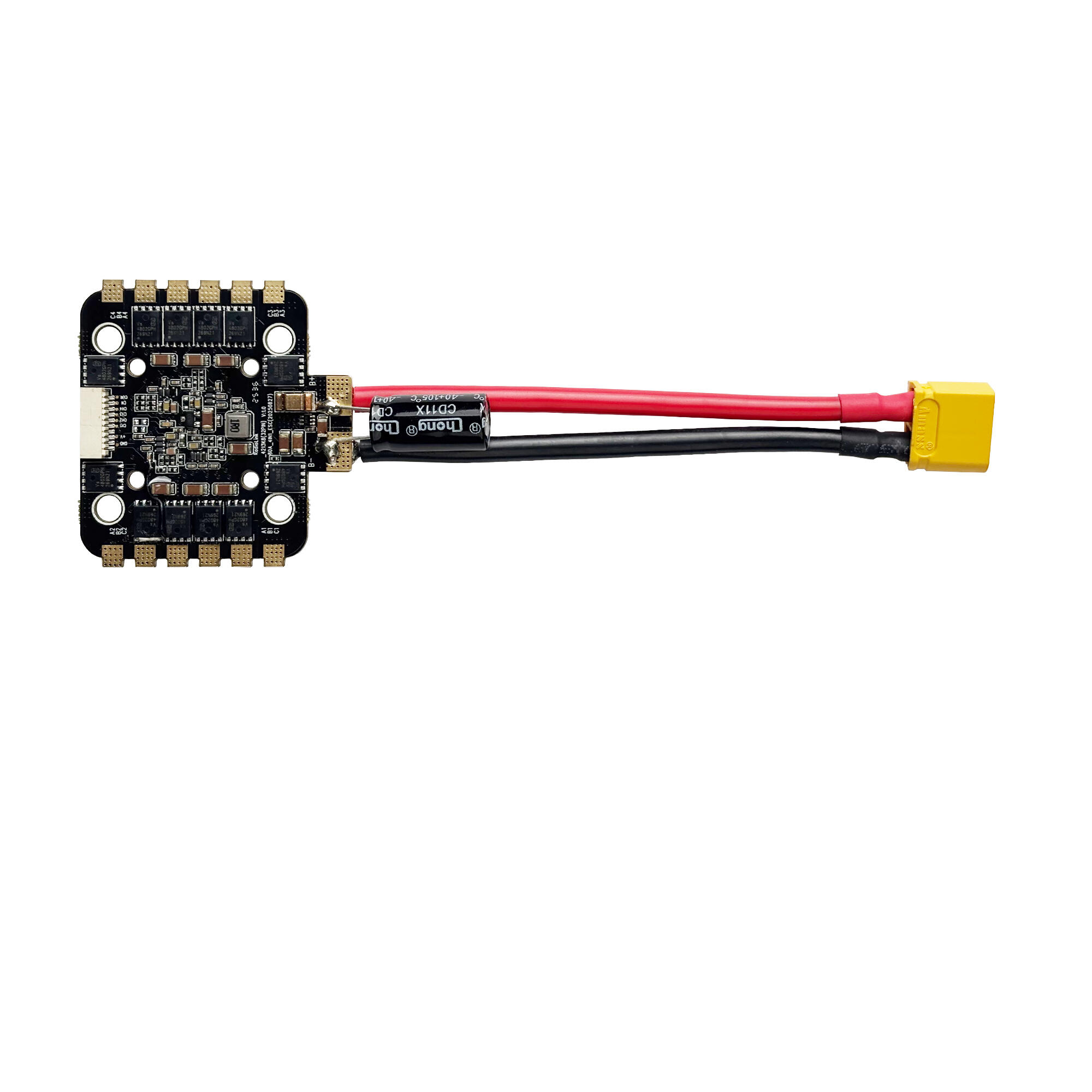
ESC |
FLYCOLOR 30A |
4 |
FLYCOLOR 30A |
4 |
Propeller |
GEMFAN FLASH 5152S |
8 |
GEMFANFLASH 5152S |
8 |
Battery |
FULLYMAX 11.1V 1500mAh 25C |
1 |
FULLYMAX 11.1V 1500mAh 25C |
1 |
Image Trans |
EWRF 5.8G |
1 |
EWRF 5.8G |
1 |
Camera |
Turbowing Cyclops 3V3 |
1 |
CADDX Turtle |
1 |
OSD |
Radiolink Mini OSD (Ch/En) |
1 |
Radiolink Mini OSD (Ch/En) |
1 |
Indicate LED |
Mini Pix Status Indicate LED |
1 |
||
FPV Goggle |
Longsite 3.0 inch |
1 |
Fat Shark 4.3 inch Recon V2 |
1 |
Charger |
SKYRC E3Simple Charger |
1 |
SKYRC E3 Simple Charger |
1 |
Manual |
Soft copy |
1 |
Soft copy |
1 |
Package |
Aluminum Case: 45*30*16cm |
1 |
Aluminum Case: 45*30*16cm |
1 |
Chapter 1 Introduction
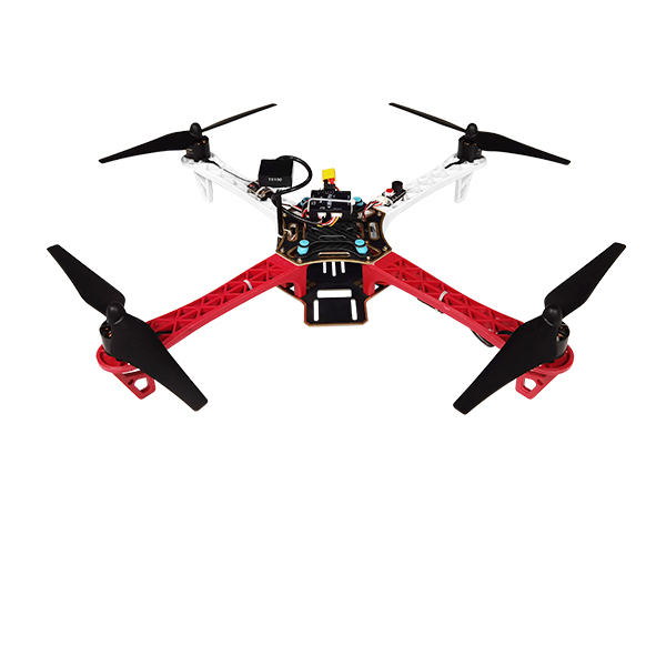
WOLF QAV210 is equipped with the flight controller Radiolink Mini Pix, fully powered by its functions of Pos-Hold, Auto Flight Mode, Waypoints Mode and RTL, perfectly works with Radiolink GPS with centimeter position accuracy to realize the function of pos-hold videography.
The Kalman Filter Algorithm applied in Mini Pix correctly calculates the acceleration and gravity change at high speed and makes QAV210 Advanced possible to realize fast elevation at Alt-hold mode and well record every moment with super fast movements.
1.1 Feature Highlights
120KM/H High-speed Aerial Videography Record every exciting moment of F1 racing game, even volcano explosion
Racing Trainer Aircraft Beginners can start from Alt-Hold Mode, easy and handy. Only 2-3 batteries needed to master the flight.
FPV&DVR Dual-Function Camera, real-time record
WOLF QAV210 Advanced is equipped with CADDX Turtle 1080P 60fps mini video camera, specially for racing drone. The DVR transmits the images and records simultaneously, recording every exciting moment
WOLF QAV210 Standard is equipped with Turbowing Cyclops FPV&DVR dual-function mini camera.
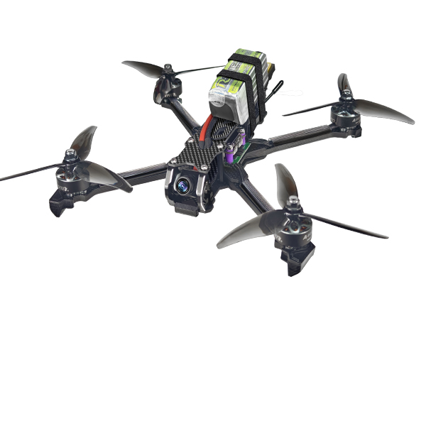
The powerful system is assembled with renowned components in drone industry including GEMFAN propellers, FLYCOLOR ESC, SZ-SPEED motor, FULLYMAX battery, Radiolink transmitter to maximize the efficiency and offer the best athletic experience with best power.
More details please find the below links:
WOLF QAV210 Standard:https://www.radiolink.com/wolf_qav210
WOLF QAV210 Advanced:https://www.radiolink.com/wolf_qav210_advanced
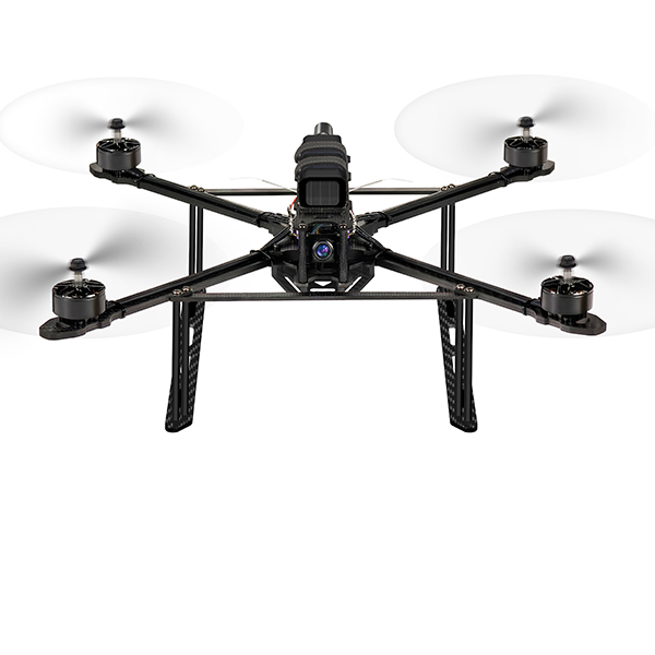
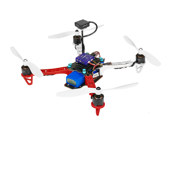
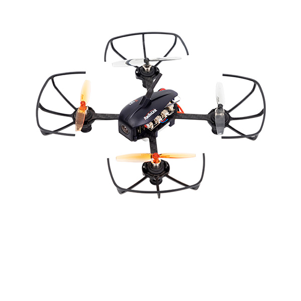
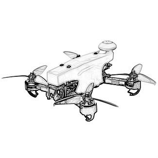
1.2 About WOLF QAV210
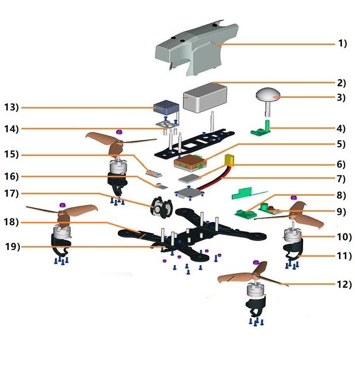 Cover
Cover
lithium battery
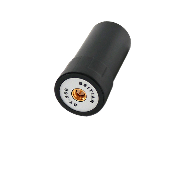
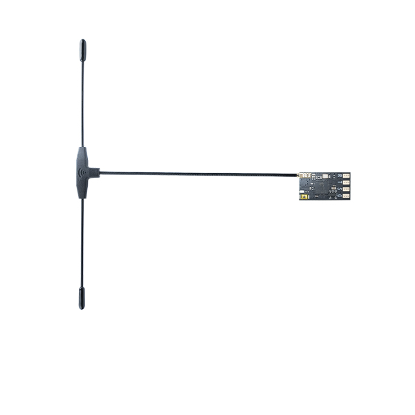
Image Transmission (IT) antenna
II module
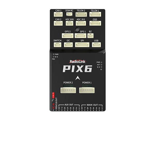
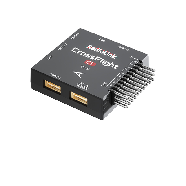
F.C(Mini Pix)
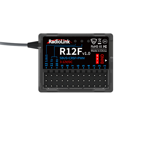
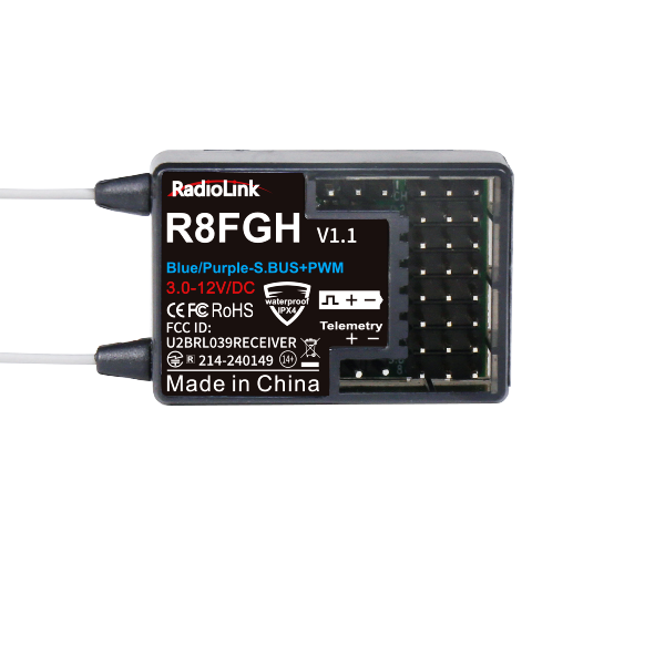
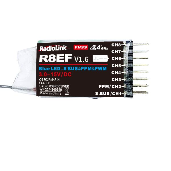
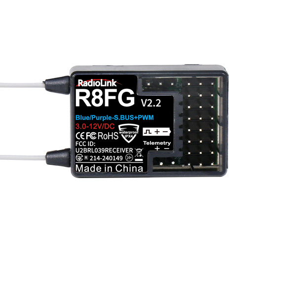
RX (R12DSM/R8FM)
Power module
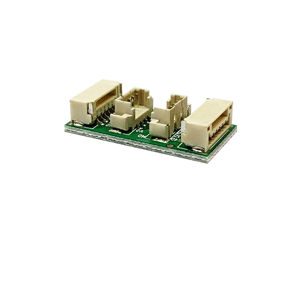
MINI IT OSD
Safety Button(Unlock flight )
Motor
Landing gear
Propeller
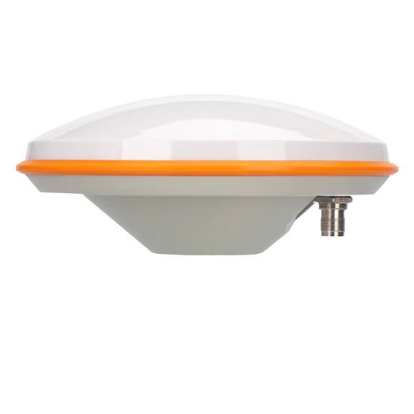
MINI M8N GPS(TS100)
GPS carriage
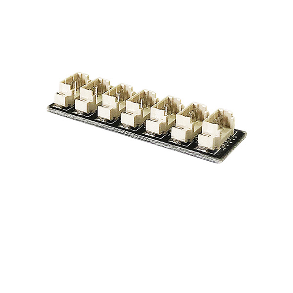
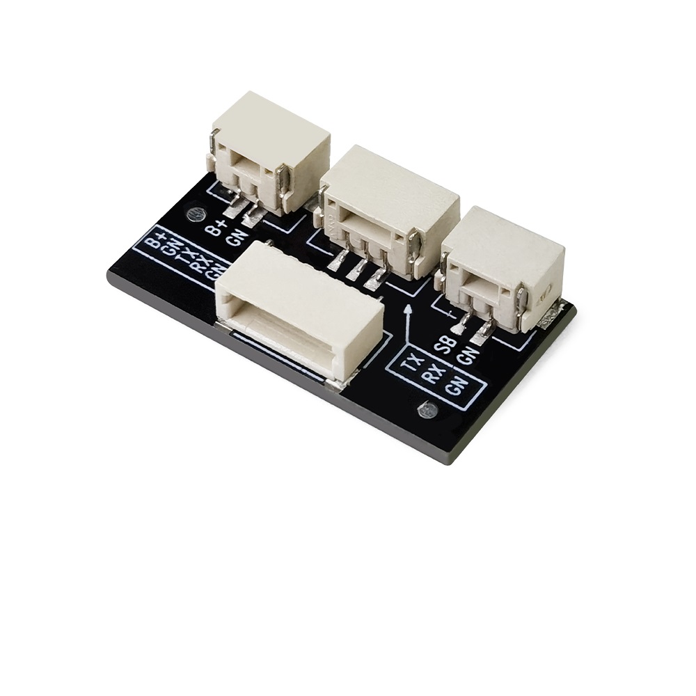
I2C interface board
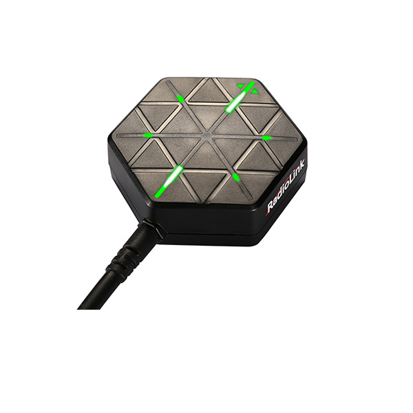
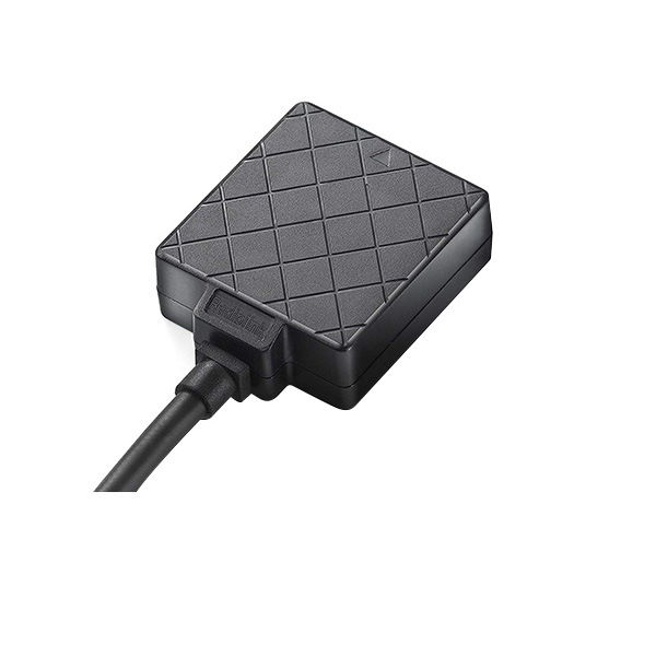
FC status indicate LED
FPV&DVR Dual-function Camera
ESC
Carbon fiber main plate
1.3 Prepare WOLF QAV210
WOLF QAV210 RTF set is packed by aluminium case with all accessories installed, including parameters of transmitter and fight controller are done setting. When receive the set, all pilots need is to plug fully-charged lithium batteries in the transmitter and the aircraft and then it is ready to fly.
If the aircraft is left unused for a long time, it is strongly advisable to uninstall the propellers with the professional tool packed in the set and to (dis)charge the batteries to best storage status, that is, 3.8V per cell to avoid unexpected damage and to extend the product life span.
1.4 Prepare Transmitter
WOLF QAV210 has two versions, including stand-alone version and RTF version.
① pilots who purchase the stand-alone version, please follow the appropriate transmitter manual to install the receiver and bind the aircraft with the transmitter after receiving WOLF QAV210.
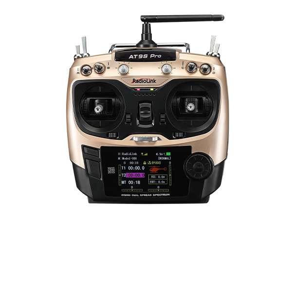
② RTF version includes the standard version with 8CH transmitter T8FB and the advanced version with 10/12CH transmitter AT9S.
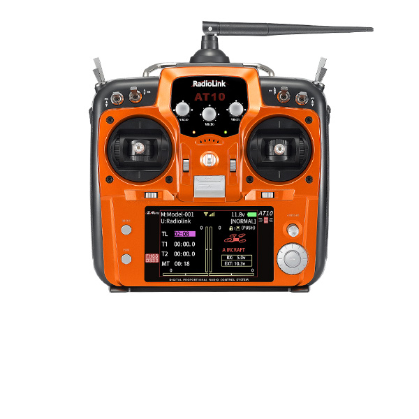
Always ensure all batteries have been properly charged prior to using the transmitter. T8FB works with Lithium 2S-4S battery or 4 pieces AA battery while AT9S/AT10II works with Lithium 2S-4S battery or 8 pieces AA battery. To avoid batteries over discharged, alarm of low voltage can be set after connecting plug batteries in transmitter.
T8FB is developed as self-adapted alarm by default and it will automatically give an alarm when the voltage becomes low depending on either 2S or 3S battery pilots use. As to AT9S/AT10II, please press “MODE”to enter the BASIC MENU => Select “PARAMETER”and enter=> Set “TX-ALARM” according to the actual battery used. For example, if batteries used in pilots transmitter is 2S, then it’s 4.2V*2S=8.4V when fully charged. As the voltage of a single cell is 3.7V, we usually set the low voltage alarm as 3.7V*2S=7.4V.
Chapter 2 Aircraft Setup
WOLF QAV210 consists of flight controller system, remote controller system, GPS system, power system, image transmission system. This chapter is about the aircraft’s components and the feature of each function.
2.1 RTF Version Setup
Radiolink WOLF QAV210 has two sets, including stand-alone version and RTF version.
RTF version means Ready to Fly. Pilots only need to power on the transmitter and the aircraft and unlock the both prior to flight.
2.1.1 Basic Operation of the Transmitter
As the aircraft is controlled to realize all movements by operating the remote controller, it’s important to know its basic operation.
Remote controller is also called transmitter and should work with a receiver. Transmitter in a pilot’s hand and receiver in an aircraft to work as the flight controller system. Currently transmitters on the market are 2.4GHz (2400MHz~2483.5MHz).
The 4 basic channels of all transmitters are always the same: CH1- Aileron/Roll; CH2- Elevator/Pitching; CH3-Throttle; CH4-Rudder.
These four basic channels are operated by the two sticks on the transmitter. Most transmitters have not only these 4 channels but also other auxiliary channels such as switches for changing fight modes, controlling PTZ and camera. These commands will be passed to the receiver on aircraft via wireless signal by the emission system of transmitter. So we usually name the channels besides 4 basic ones auxiliary channels.
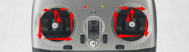
The left stick controls the throttle by toggling up and down to make aircraft lift and descend vertically and the rudder by toggling left and right to make aircraft turn clockwise and anticlockwise.
The right stick controls the elevator/pitching by toggling up and down to make aircraft forward and backward and the aileron/roll by toggling left and right to make aircraft move left and right horizontally.
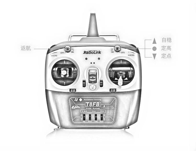
Here is a picture showing T8FB as an example while AT9S/AT10II is operated as the same way:
More details about T8FB, please download the manual via the below link: https://www.radiolink.com/filedownload/38824
More details about AT9S Pro, please download the manual via the below link:
https://www.radiolink.com/filedownload/45526
All Radiolink products manuals available via the below link:https://www.radiolink.com/manuals
2.1.2 Arm
2.1.2.1 Arm QAV210
Power on the transmitter and aircraft, make sure the throttle stick is at the lowest position and press the safety button (Red) till the indicate LED is always on instead of flashing.
2.1.2.2 Arm Transmitter
When the safety button on QAV210 is always on, pilots have better keep distant from the aircraft to ensure the safety and check the current flight mode. The transmitter can only be armed under the Stabilize Mode and Alt-hold Mode.
Arm and Disarm (Shown with Radiolink T8FB as below. AT9S/AT10II can be (dis)armed as the same way):
Arm with Left Throttle: Toggle the left stick(Throttle) to the right bottom for 2s and a beep sound can be heard from the aircraft. The indicate color on flight controller will be flashing blue. Slightly push the throttle at the Stabilize Mode (If at Alt-hold Mode, the throttle better to be pushed over the central point), the motors and propellers start moving means the aircraft is successfully unlocked.
Disarm with Left Throttle: Throttle to the left bottom for 2s, the motors stop moving.
Arm with Right Throttle: Toggle the left stick to the right bottom while the throttle/right stick to vertical bottom for 2s and a beep sound can be heard from the aircraft. The indicate color on flight controller will be flashing blue. Slightly push the throttle at the Stabilize Mode (If at Alt-hold Mode, the throttle better to be pushed over the central point), the motors and propellers start moving means the aircraft is successfully unlocked.
Disarm with Right Throttle: Toggle the rudder/left stick to the left bottom while the throttle/right stick to vertical bottom for 2s, the motors stop moving.
Note: When the aircraft is to land, it is advised to change the flight Mode to STABILIZE MODE because it will be easier to disarm. Toggle the throttle to the vertical bottom for about 5s till the propellers stop moving then disarm the transmitter as the above steps. Otherwise the aircraft may be repeatedly up and down or rolled over as the result of trying to disarm in a rush.
When the transmitter is successfully disarmed, please make sure to long press the safety button of the aircraft till the RED indicate LED flashes.
At the Alt-hold Mode, the aircraft cannot take off until the throttle is moved over the central point. When the aircraft rises to a certain height, it will remain at this altitude if the throttle is back to the central point.
2.1.3 Flight Modes Introduction
WOLF QAV210 has four flight modes by default: Stabilize Mode, Alt-Hold Mode, Pos-Hold Mode and RTL Mode.
In Chapter 2.1.1 Basic Operation of the Transmitter, the functions of auxiliary channels were mentioned. One of those is to switch the flight mode.
For T8FB, Ch3 (SWB on the right) by default, UP is Stabilize Mode, MID is Alt-Hold Mode, DWN is Pos-Hold Mode while CH2 (SWA on the left) DWN is RTL Mode.
For AT9S, Ch3 (SWC on the right) by default, UP is Stabilize Mode, MID is Alt-Hold Mode, DWN is Pos-Hold Mode while CH2 (SWD on the left) DWN is RTL Mode.
2.1.3.1 Stabilize Mode
Pilots use rolling and pitching to control the inclination angle of the aircraft. When the roll/pitch stick is loose, the aircraft will be automatically back to horizontal status. With the windy weather, pilots need to continuously correct the rolling and pitching angle to keep the aircraft at the same position.
Pilots use the rudder stick to control the turning velocity. When the rudder stick is loose, the aircraft will keep the direction.
Pilots use throttle to control the average rotation rate of the motors and need to continuously toggle the throttle to remain the aircraft at the certain height. The throttle input will automatically change according to the aircraft inclination to cohere with height change brought by the aircraft inclination, eg. If the inclination angle is too big, it will automatically increase.
2.1.3.2 Alt-Hold Mode
At Alt-Hold Mode, flight controller will automatically control the throttle to remain the height. The operations of rolling, pitching and rudder are to directly control the turning angle and direction of the aircraft, same as Stabilize Mode.
Comparing with Stabilize Mode, the Alt-Hold Mode is easier to control because the aircraft will remain at a certain height if the throttle stick is at the central point after pilots toggle it over to lift. And they only need to toggle the rolling/pitching stick to make the aircraft move (forward/backward/left/right), which is easier for beginners to practice.
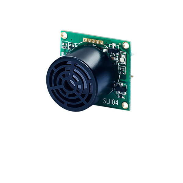
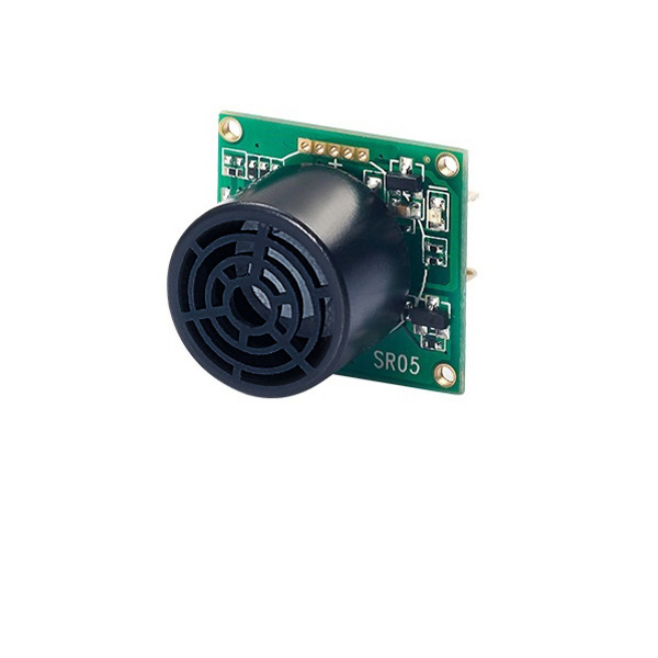
WARNING! Flight controller takes the test result made by barometric altimeter as the height base. If the pressure changes, the height could possibly be incorrect, which is not the actual height. Unless the ultrasonic module is installed to detect the distance and the flight height is less than 20 feet. Ultrasonic sensor can detect flight height more accurately if less than 26 feet.
Stick Operation at Alt-Hold Mode
Throttle stick is to control the rising and descending velocity of the aircraft.
Aircraft remains the height when the throttle is held at middle point (between 40%-60%)
If the throttle is toggled out of this range, the aircraft will be up or down to varying degrees. The max distance of rising or descending is 2.5m/s.
Take-off at Alt-Hold Mode
At Alt-Hold Mode, only the throttle stick is pushed over the central point can the aircraft be lifted. When the aircraft reaches certain height, toggle the throttle stick back at the middle, it will remain at the same altitude.
Landing at Alt-Hold Mode
At Alt-Hold Mode, toggle the throttle slowly to the bottom to land the aircraft. Once landed, the motors won’t stop immediately. If pilots disarm the aircraft immediately by pulling the throttle stick to the bottom outside corner, the aircraft will possibly rolling over. It’s better to wait for 10 more seconds till the aircraft detects landing and the motors stop completely to lock.
2.1.3.3 Pos-Hold Mode
At Pos-Hold Mode, the aircraft will automatically keep current position, direction and altitude. That is, the aircraft will remain the same position if pilots don’t toggle sticks. But they can still take rolling and pitching stick to make the aircraft move forward/backward/left/right, as the other flight modes.
To realize the good performance of Pos-Hold mode, the GPS, satellite searching, low disturbance of electromagnetism and low vibration are all very important factors.
When using the Pos-Hold Mode or RTL Mode, pilots have better to wait for 1 minute until the satellite searching of GPS reaches 14 stars or above after powering on the aircraft and the modes will work better. The satellite searching depends on the actual weather and landform.
Note When at Pos-Hold Mode, the aircraft can’t be armed if the satellites are less than 9 stars or the accuracy is more than 1.2 meters.
2.1.3.4 RTL Mode
When change to RTL mode, the aircraft will return to the place where it initially took off. By default, aircraft will firstly fly up to the height of at least 15m before returning. Or, if the aircraft is higher than 15m when RTL Mode is on, it will decrease to the height of 15m then return. If pilots enjoy the flight around the obstacles that higher than 15m, make sure to set up the RTL height in Mission Planner. The detailed setup steps please refer to instruction manual of Radiolink Mini Pix downloaded via : https://www.radiolink.com/filedownload/41992
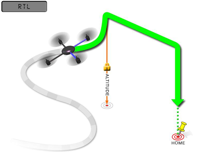
RTL Mode works with GPS, which is indispensable to locate before changing to this Mode. The Mode commands the aircraft to return “HOME”where it takes off. Therefore, “HOME”should always be the place that the GPS locates where the aircraft actually takes off, without obstacles and far away from crowds.
2.1.4 RTL Mode Enabled
Besides manually enabled by pilots (Switch on SWA of T8FB or SWD of AT9S), RTL Mode of WOLF QAV210 can be automatically activated under the below two situations:
Signals lost. WOLF QAV 210 will activate the RTL Mode by itself.
Low voltage. When the voltage is lower than 10.6V (with 3S lithium battery) after a period of flight, WOLF QAV 210 will activate the RTL Mode by itself. It will automatically rise up to a certain height (15m by default) and then land on the point that it takes off. By the moment, QAV210 won’t move even if pilots toggle the transmitter sticks. Please lock the aircraft once landed and disconnect the battery and get it charged.
2.2 Stand-alone Version Setup
As all parameters of transmitter and aircraft have been set, the RTF version is ready to flight once purchased. But as the stand-alone version doesn’t go with a transmitter, parameters of the transmitter need to be set though that of RTF version has been done.
Pilots who purchase stand-alone version of WOLF QAV210 need to: install Mission Planner to work with the flight controller, bind the transmitter and receiver and get the parameters set, calibrate the ESC and install the props.
Note: WOLF QAV210 Stand-alone version is also compatible with the transmitter and receiver of the other brand. But please make sure that the receiver is SBUS/PPM supported.
2.2.1 Binding Transmitter to WOLF QAV210
Every transmitter owns a unique ID code. Before using, binding transmitter to receiver on aircraft is a must. When done binding, ID code will be stored in the receiver, no need to rebind.
If pilots’ transmitter has done binding with receiver, only need to connect the receiver to the Mini Pix flight controller after receiving the stand-alone version of WOLF QAV210.
Binding the transmitter to the receiver is essential. Otherwise, the aircraft cannot take off.
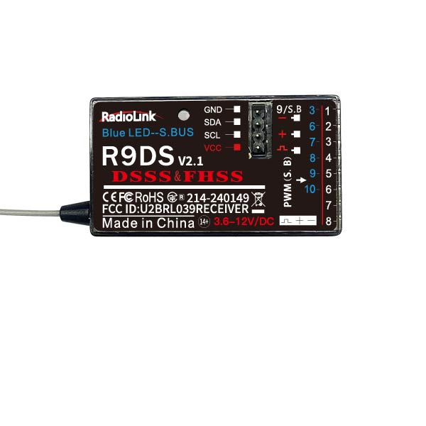
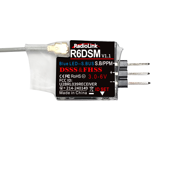
Radiolink receivers R12DSM/R6DSM are compatible with transmitters AT9/AT9S/AT10/AT10II while R8FM is compatible with transmitter T8FB.
Binding steps of all Radiolink transmitters and receivers are the same as follow:
Put the transmitter and the receiver together within 1 meter.
Power on the transmitter and the receiver. The receiver will bind to the closest transmitter.
Press the ID SET on the side of the receiver for more than 1s, the flashing LED means binding starts. When LED stops flashing, binding is complete.
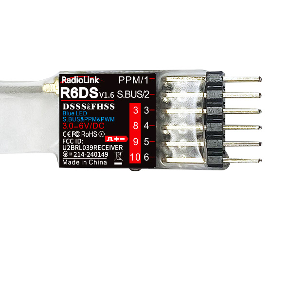
When binding is done, please check if the receiver change to SBUS/PPM output . Generally we use SBUS signal. LED on all receivers from Radiolink is blue/purple means SBUS signal while red means PWM signal. Pilots can short press the binding code twice within 1s to switch the signals output of the receiver.
2.2.2 Installation of Mission Planner
To run the Mission Planner installation, NET. Framework from Microsoft is needed. Link is as below
https://dotnet.microsoft.com/download/thank-pilots/net462
Download link of Mini Pix Mission Planner: https://www.radiolink.com/minipix_missionplanner
Before setting the parameter, please install the Mission Planner first.
Steps to install the Mission Planner, please refer to the video as below:
https://www.youtube.com/watch?v=twW9CaRlj-U&t=1159s (Starting from 13:00)
2.2.3 Transmitter Parameters Setup
The flight controller of WOLF QAV210 has been set with all necessary parameters before purchasing. For the stand-alone version, please calibrate the transmitter sticks, set the flight modes and Fail Safe.
2.2.3.1 Transmitter Calibration
Before the transmitter sticks calibration in Mission Planner, please make sure the model type selected in transmitter is multi-rotors and the phase is REVERSED. Below detailed steps take AT9S as an example while T8FB can be directly calibrated with sticks. For the calibration of other brands’ transmitter, please kindly refer to the its instruction manual.
Press “MODE” for more than 1s to enter the BASIC MENU and choose “MODEL TYPE”, rotate the dial to select “MULTIROTORS”and press “PUSH”to save, then “END”to exit.
Note: For AT9S, the throttle phase needs to be set REV while that of T8FB and AT10II are REV by default.
Press “MODE”for 1s to enter the BASIC MENU and choose“STEERING REVERSE”and select 3: THROTTLE. Then “PUSH”to select and rotate the dial to “REV” and “PUSH”to confirm then “END”to exit.
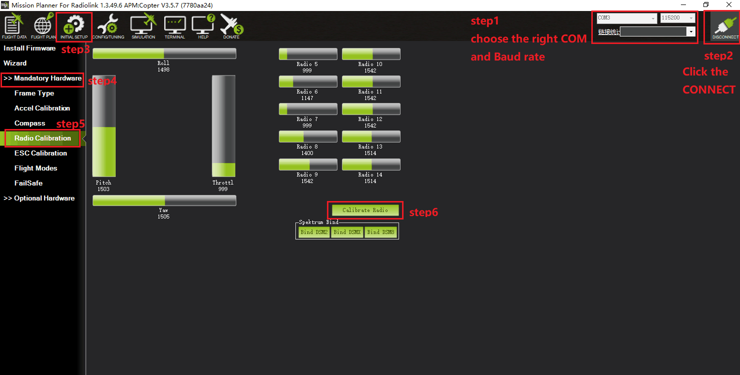
Make sure binding between the transmitter and the receiver is complete before connecting Mini Pix with Mission Planner on computer via USB cable with the Baud Rate of 115200 . The connection between Mini Pix and Mission Planner can be also achieved by data transmission with the Baud Rate of 57600. Then power on the transmitter. Press PUSH to unlock the transmitter if no operation for a long time and it enters standby mode.
Open Mission Planner => select the corresponding Baud rate and port => click to connect => INITIAL SETUP =>MANDATORY HARDWARE => RADIO CALIBRATION =>CALIBRATE RADIO
Note: Ports varies from different computers. Please select the correct port to connect. Connection may fail with several ports in use. Please remove the other connections.
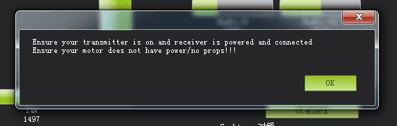
There will be a safety reminder as below shown popping out when pilots click “Calibrate Radio”. Please double check before clicking “ok”.
Note: It’s strongly advised to install the propellers AFTER all parameters setup with the consideration of safety.
And then click “OK” and move all RC sticks and switches to their ultimate positions so the green bars reach the limits/red lines.
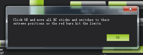
Joysticks can be calibrated as following , both (Ch1 to Ch4) are pushed to the limits(up/down/left/right)
Note: AT9S/AT10II/AT9/AT10 can be calibrated as the below example T8FB
If the green bars do not change when pilots toggle the sticks, please check if the receiver has connected successfully. Also, check if every corresponding green bar for every channel works as listed:
CH1: low position = roll (towards the left), up position= roll (towards the right).
CH2: low position =pitch(forward), up position =pitch(backwards).
CH3: low position =reduced speed (downward), up position =speed up(upward).
CH4: low position = yaw (anti clockwise), up position = yaw (clockwise).
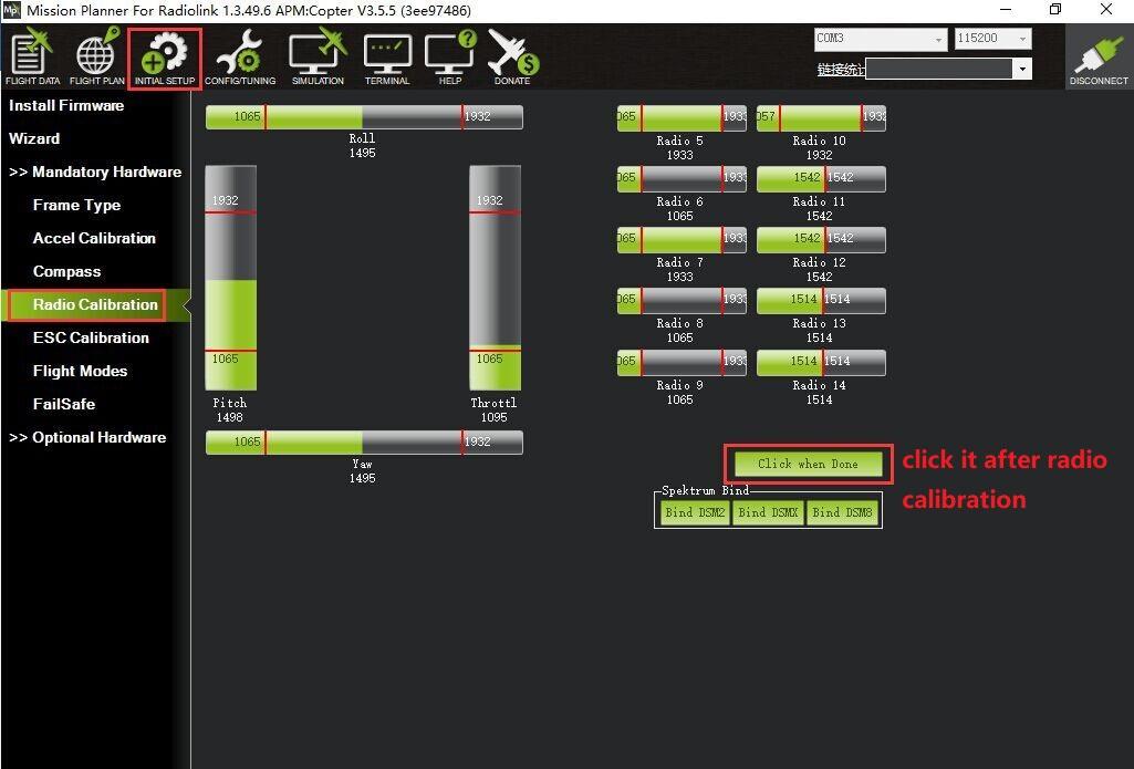 After each green bar reaches the limits/red lines, click the green button at bottom right to complete the transmitter calibration.
2.2.3.2 Flight Modes Setup
Setup in transmitter
Setup steps of Radiolink transmitter(T8FB/AT9S/AT10II) and flight controller with Mission Planner are as below. For the transmitters from other brands, please select CH5 to set flight modes and SBUS output in receiver.
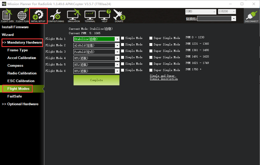
Mini Pix has various flight modes for option. But WOLF QAV210 is with four flight modes as factory setting by default including Stabilize Mode, Alt-Hold Mode, Pos-Hold Mode and RTL Mode. Therefore, if no other flight modes needed, pilots just set the flight modes in transmitter corresponding to those in flight controller.
The default parameters of T8FB is set as that of Mini Pix. If it is the transmitter model of T8FB purchased with WOLF QAV210, then this part can be skipped as the flight modes are already set identical. Pilots only need to calibrate joysticks and ESC.
Note: The following steps take AT9S as example, AT10II/AT10/AT9 can be set as the same way
When binding completed between transmitter and aircraft/receiver, click INITIAL SETUP =>MANDATORY HARDWARE => FLIGHT MODES
Then power on transmitter => long press MODE to enter BASIC MENU => short press MODE to ADVANCED MENU => press PUSH to enter ATTITUDE
Default channel is CH5 while setting the 3-way switch as SWC and the 2-way switch as SWA or SWD, pilots can personalize the setting basing on own flight habits
Note: The PWM value ( RATE on the second column as below shown) can be modified with corresponding POSI (eg. UP-UP) while SWT is (ON). Toggle positions of SWC and SWA/SWD to select different POSI.
When flight mode 1 in MP is Stabilize, the first ATTITUE on transmitter should be set as
Stabilize and the corresponding parameters setup in MP should be set as below:
Check the first attitude, if POSI is (UP-UP) . If not, please toggle the switch to the right position with - swt- is on
Turn the dial to the percentage rate on the transmitter LCD screen and PUSH to select and turn the dial to modify
Check the PWM value of the corresponding flight mode on MP
When setting the PWM value on transmitter, the corresponding PWM value on MP will change accordingly. Each flight mode has the PWM range and when the value is within, it means the current mode is set. Meanwhile, the selected mode on MP will turn dark green. That is , turning the dial on the transmitter to modify the RATE to make sure the corresponding PWM value on MP is within the range. Flight mode 2/3/4/5/5 can be set as the same way.
The 2-way switch is needed when setting Mode 4 to 6. Toggle this switch to the corresponding mode and can be set as the above step 3.
2.2.3.3 Failsafe Setup
The function of Failsafe on Mini Pix is set with MP menu.
Entering the Failsafe menu on MP, a note will pop out to remind no propellers installed for safety.
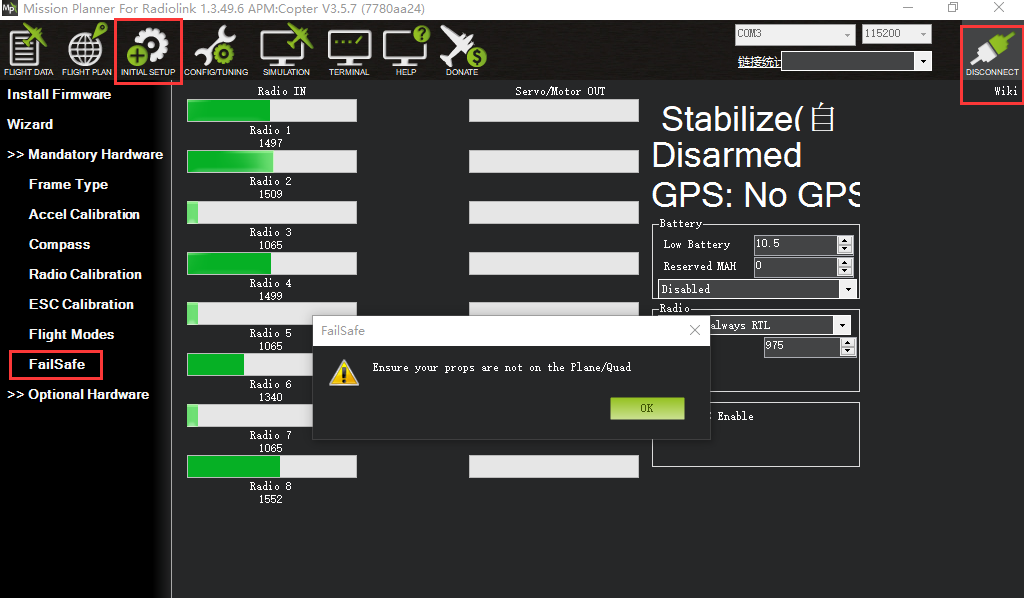
Click OK to setup:
There are different parameters setting such as throttle PWM, battery voltage to enable Mini Pix failsafe function. When the set parameter is reached, eg. If the throttle PWM value or the voltage is lower than the value set, then the failsafe is enabled and the aircraft will take corresponding action such as Return to launch(RTL), Continue to flight and Landing. To ensure the aircraft safety, RTL is normally set as the action following failsafe enabled.
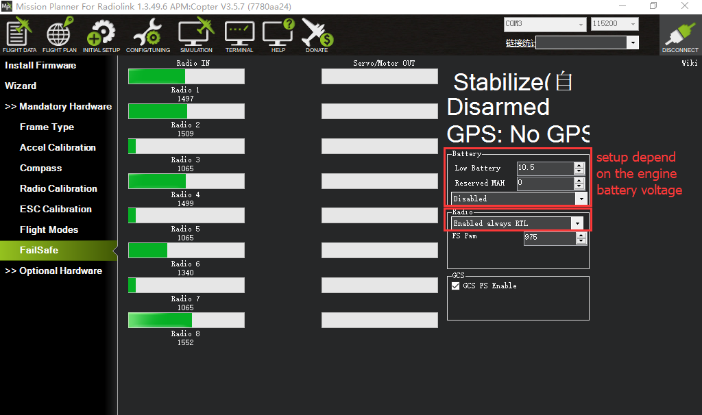
Battery Failsafe Set
Battery failsafe can be set basing on the aircraft voltage consumption, battery volume or flight distance to ensure the aircraft returning when the battery voltage is lower than the set value. This value should be set according to the battery volume. Each battery cell should be 3.7V for long distance flight while the set voltage is 3.7V times battery cell quantity. For example, the voltage value set for 3S battery is 3.7V*3S=11.1V. When it’s lower than 11.1V, the failsafe function will be enabled and the aircraft will Return to Launch automatically.
Battery detector needs to be set in MP to realize the RTL mode with low voltage.
To activate the battery detector:
• Monitor- 4 Battery and voltage
• Sensor- 0: Other
• APM version- 4: The Cube or Pixhawk
To inactivate the battery detector:
• Monitor- 0 disable
When the detector is activated, the data could possibly fail to display. Please disconnect the flight controller from the computer and repower on the flight controller then open the above sheet to input the measured voltage. When 2. Battery Voltage (Caled): the voltage displayed is same as the input value and no change means setup with success. When different, please reopen the sheet and input the measured voltage.
Note: If fail to setup, the aircraft may be impossible to arm, or buzzer may keep the Dee sound after arming, please reset to correct. If failsafe function is always on, the battery low voltage protection maybe activated and the detected voltage is INACCURATE. Please measure the voltage and input the correct value.
Throttle Failsafe
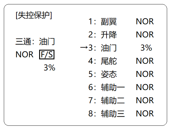
Transmitter Setup
Pull the throttle trim lever to -120 => Long press MODE to BASIC MENU => Turn the dial to select F/S(FAILSAFE) and push to enter=> Turn the dial to select CH3:THRO => Pull the throttle stick to the bottom => Long press PUSH to get the throttle percentage 3% => Press END to the main display => Push the throttle trim lever back to 0. The Failsafe setup is complete.
Mission Planner Setup
After setting failsafe on transmitter, power it off and check the FAILSAFE menu on MP if the PWM value of CH3 is smaller than 975. If yes, than the FAILSAFE function is successfully set. Otherwise, the above steps need to be repeated.
In the RADIO block on the right of the sheet, set ENALBLED always RTL and FS Pwm as 975.
2.2.4 ESC Calibration (First flight)
ESC calibration varies depending on different ESC brands, so it’s advised to refer to the ESC instructions. Never install propellers before calibrating ESC for safety.
Make sure the aircraft is well connected and radio calibration is done and can be armed;
Toggle the throttle stick to the highest point and power on the aircraft. When seeing the LED on flight controller is flashing with red/blue/yellow, power it off. The flashing colorful LED means the aircraft is ready to go into ESC calibration mode next time repower.
Repower on the aircraft, wait to check if the LED flashes (about 30s). Then long press the safety button until hearing the musical tone (the regular number of beeps indicating battery’s cell count i.e. 3 for 3S, 4 for 4S) and then an additional two beeps to indicate that the maximum throttle has been captured.
Pull the transmitter’s throttle stick down to its lowest position, another musical tone will be heard, meaning the Minimum throttle has been captured and the calibration is complete.
Push the throttle a bit to test if the ESC spin. If yes, then the calibration is done with success. If no, please repeat the above steps to recalibrate.
Hold the throttle to Minimum and disconnect the battery to exit ESC calibration mode.
When all the above parameters set, propellers can be installed and arm the aircraft. For the arming steps, please refer to 2.1.2 RTF version Armed
WOLF QAV210 racing drone is equipped with Radiolink MINI M8N GPS TS100 as factory default. If the Pos-Hold Mode and RTL Mode are needed, please go to outdoor open space and these two modes can be achieved when the satellites searched by GPS.
Green indicator on GPS TS100 flashes means satellites have been captured. It needs to wait a bit longer (about 1.5-2 minutes, and longer in cloudy day) after powering on QAV210 for the first flight to make sure the satellite captured reaches 18 or above. In this case, the accuracy of Pos-Hold and RTL will be better.
2.2.5 Propellers Installation
WOLF QAV210 stand-alone version is NO propellers installed for the package reason. So when the above steps are done setting(parameters set, ESC calibrated, arm successfully after powering on), propellers are ready to be installed. Make sure the correct installation of each positive/counter propeller. otherwise the aircraft may fail to take off.
As the image shown below, put the head with camera forward when installing props and make sure propellers on Motor 1 and 2 rotate counter clockwise while that on Motor 3 and 4 are clockwise.
Note: Never install the props when setting parameters of aircraft to ensure the safety.
WOLF QAV210 is equipped with Radiolink MINI M8N GPS TS100 as factory setting. If the Pos-Hold Mode and RTL Mode needed, please go to an open space and wait till the satellites searched to enjoy the flight.
Green indicator on GPS TS100 flashes means satellites searched. It’s advised to wait some time (about 1.5-2 mins) for searching satellites at the first flight. And it will be a bit longer in cloudy weather. The quantity of the satellites searched reaches 18 or above will ensure the pos-hold and RTL accuracy.
2.2.6 Note
When arming with success, make sure to stay a certain distance away from the aircraft to ensure safety.
Make sure to flight outdoor at an open space
Gently push the throttle when start the flight: Under Alt-Hold mode, push the throttle a bit higher than the central point and WOLF QAV210 will slowly take off and keep rising if keep pushing the throttle. When QAV210 reaches a certain height, it will hover if stop pushing the throttle. Pilots can change directions by rolling, pitching and yawing.
Never get close to the aircraft when propellers are on move to avoid getting hurt.
Never get close to power off the aircraft until making sure it is disarmed.
It’s advised to be accompanied with experienced pilot for the first flight.
Chapter 3 Flight
3.1 Visual Flight
At the beginning, it’s advised to flight visually by practicing basic movements like flying forward/backward/leftward/rightward and hovering.
For example, beginners can try hovering under the stabilize mode by toggling the joysticks to adjust the aircraft to remain the same position. Then the horizontal 8 training for the next step.
3.2 FPV Flight
Different from visual flight, FPV is first person view with the help of a goggle or a screen. Theoretically, FPV flight is easier than visual flight because pilots can clearly judge the moment to turn or forward with goggle or screen.

3.2.1 FPV Goggle
VR goggles for standard and advanced version of WOLF QAV210 are different. The standard version is equipped with the 3-inch FPV goggle from LONGSITE while the advanced one equipped with 4.3-inch FPV&DVR dual functions goggle from FATSHARK.
Both goggles have built-in image transmission receiver. Pilots only need to bind the goggle with the transmitting module before flight.
User instruction of LONGSITE 3-inch FPV goggle

① Short press for menu displays, long press for more than 3s to power on/off.
② Short press for automatic search and channel with best signal will be selected.
③ Short press band+ with circular band changes from A - B- E - F - R.
④ Short press channel+ with circular channel changes from 1 - 2 - 3 - 4 - 5 - 6 - 7 - 8
⑤ Cotton to ensure pleasant wearing
⑥ Mini USB charging port for DC5V only
⑦ Antenna port A: RP - SMA male connector
⑧ Charging indicator: red ON for charging, OFF for fully charged
⑨ Antenna port B: RP - SMA male connector
⑩ Audio port: Output audio signal with transmission mode and video signal with AV mode.
Adjustable headband
Menu instruction:
When under standard mode, press key 1 to enter menu mode.
When under menu mode:
① Key 1: Select OPT
② Key 2: Back to standard mode
User instruction of FATSHARK 4.3-inch Recon V2 FPV&DVR dual function goggle
Brightness/ Contrast: Slide the 5-way button left and right or forward and back for contrast and brightness adjustment.
Channel Selection: Short press channel Up(CH+)/Down(CH-) to select from Ch1 to Ch8; Long press (CH+) for 1s to change band Fat Shark(FS)/ RaceBand/ Band A/B/E; Long press (CH-) to enable auto scan active channel.
DVR Recording: Vertically press the 5-way button and a short beep will be heard with a red REC displayed on the goggle screen and flashing means recording starts. A long beep after another vertical press of the 5-way button means recording off with the red REC disappear. Long press the 5-way button to enter the DVR menu. This DVR has no auto save recording file function and needs to be saved by stop recording manually.
FATSHARK 4.3-inch Recon V2 Frequency Table
Name |
CH1 |
CH2 |
CH3 |
CH4 |
CH5 |
CH6 |
CH7 |
CH8 |
Fat Shark /IRC |
5740 |
5760 |
5780 |
5800 |
5820 |
5840 |
5860 |
5880 |
Race Band |
5658 |
5695 |
5732 |
5769 |
5806 |
5843 |
5880 |
5917 |
Band A |
5865 |
5845 |
5825 |
5805 |
5785 |
5765 |
5745 |
5725 |
Band B |
5733 |
5752 |
5771 |
5790 |
5809 |
5828 |
5847 |
5866 |
Band E |
5705 |
5685 |
5665 |
5645 |
5885 |
5905 |
5925 |
5945 |
When flight with FPV, pilot select the preferred frequency transmission channel with the above table or choose the automatic searching to pair the frequency.
3.2.2 FPV Camera Instruction
Cameras equipped with WOLF QAV210 standard version and advanced version are different.
That of the Standard version is Turbowing Cyclops 3 V3 720P FVP&DVR dual function camera while that of the Advanced version is 1080P FVP&DVR dual function camera with 60 frame/s.
Instruction of Turbowing Cyclops 3V3 720P FVP&DVR dual function camera
Enable Recording Function:
Short press the button to start or stop recording. The flashing red led indicates recording while always on indicates stop recording.
After inserting TF card, the recording duration will be displayed at the lower right of the output image. For example,
if “49:00:00”is displayed, it meaning the recording duration will last 49 minutes more.
Turbowing Cyclops 3V3 PWM signal input can be connected with the
PWM signal from receiver and controlled by it. When the PWM signal enters from that less than 1700us to larger than 1700us, a pulse will be output to simulate the effect of pressing recording button.
Instructions of CADDX Turtle 1080P FVP&DVR dual function camera

① Recording Button
Short press the button to start or stop recording. The flashing red led indicates recording while always on indicates stop recording.
② SD Card Slot
TF card is needed to insert into the slot when recording function is enabled.
The maximum memory capacity of SD card supported by CADDX Turtle camera is 64G. The resolution ratio of video is 1080P 60 frames/s with the voltage range of 5V-20V and the current of 160mA@12V.
Thank you again for choosing RadioLink product.