
Chapter 1 Introduction
1.1 Safety precautions
1) Do not use the remote controller in the rain! Avoid moisture entering the transmitter. If it is unavoidable to use this product in humid weather (such as competitions), please cover your remote controller and receiver with a waterproof cloth, and do not fly if there is lightning.
2) Do not use it in rainy and snowy weather. This weather environment will interfere with the remote controller equipment, resulting in loss of control and accidents!
3) Do not use this equipment in crowded areas and places prohibited by national laws and regulations!
4) Do not allow children (Less than 14 years old) to touch this product. This product is not a toy. Please be careful when operating in scenes where children are present.
5) Please strictly abide by local laws and regulations when flying to ensure safe flight!
6) Make sure the throttle stick and trim button are set at the lowest end before turning on, then turn on the power button and check whether the power supply is sufficient, then turn on the receiver!
7) Check whether the various actions of servo are consistent with the direction of the corresponding joystick before operating the model. If they are inconsistent, please adjust before using!
8) Please turn off the receiver and controlled equipment before stopping use, and then turn off the power supply of the transmitter. If the operation is reversed, it may cause loss of control and cause an accident!
9) T8FB with an operating voltage of 4.8V~18V. Please do not use a battery outside this voltage range when replacing the battery by yourself.
10) The T8FB is compatible with R16SM/R8EF/R8FGH/R8FM/R8XM/R8SM/R8FG/R7FG/R6FG/R6F/R4FGM receivers. Other brands of receivers cannot be used.
11) Please refer to the website to modify the throttle hand and return to the center position joystick: https://www.youtube.com/watch?v=hp4g-NTMqMg
12) Please strictly follow the precautions and instructions to use this product. The loss caused by misuse of this product shall be borne by the user.
1.2 T8FB+R8EF introduction
1.2.1 Specifications
T8FB Transmitter | |
Size | 173*102*206mm (6.81”*4.02”*8.11”) |
Weight ((with R8EF)) | 0.47kg (13.05oz) |
Channel Quantity | 8 channels |
Control Range | 2000 meters in the air, 500 meters on the ground (actual distance depends on the environment) |
Operating Current | <80mA |
Operating Voltage | 4.8V~18V |
Output Frequency | 2.4GHz ISM band (2400MHz~2483.5MHz) |
Modulation Mode | GFSK |
Channel Bandwidth | 400KHZ |
Channel Pacing | 1200KHz |
Spread Spectrum Mode | FHSS 67 channels pseudo-random frequency hopping |
Adjacent Channel Rejection | >36dBM |
Transmitter Power | <100mW (20dBM) |
Reception Sensitivity | -104dBM |
Transmission Rate | 38kbps |
PWM Output Range | 1.0ms~2.0ms |
Section precision | 4096, 0.5us per section |
Cycle | 15ms/per frame |
Battery Box Size | 115*36*23.5mm (4.53”*1.42”*0.93”) |
Operating Temperature | -20° to 85° C (-4° to 185° F) |
Compatible receivers | R8EF(Standard), R16SM, R8SM, R8FM, R8XM, R8FGH, R8FG, R7FG, R6FG, R6F, R4FGM |
R8EF Receiver | |
Size | 41.5*21.5*11.5mm (1.63” *0.85” *0.45”) |
Weight: | 7g |
Antenna length | 210mm (8.26”) |
Channel Quantity | 8 channels |
Control distance | 2000 meters in the air, 500 meters on the ground (actual distance depends on the environment) |
Operating Current | 38-45mA@5V |
Operating Voltage | 3-15V DC |
Signals Output | PWM(red LED) and PWM&SBUS&PPM(blue/purple LED) |
Section Precision | 4096, 0.25us per section |
Compatible transmitter | T16D/T12D/T8FB/T8S/RC8X/RC6GS V3/RC4GS V3/RC6GS V2/RC4GS V2/RC6GS/RC4GS |
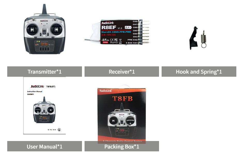
1.2.2 Packing List
1.2.3 Transmitter Overview
T8FB (Mode 2) is shown as below
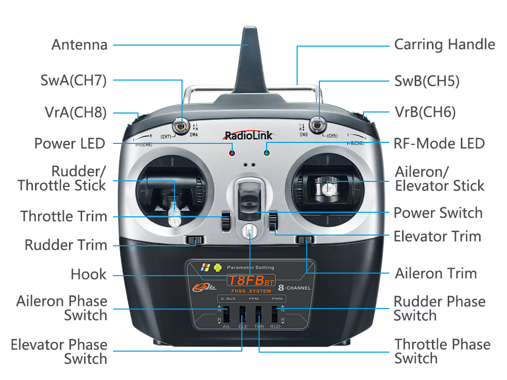
Note: The directions of the 4 channels can be easily changed by toggling the corresponding Reverse Switches instead of modifying the parameter data in the software/APP.
T8FB Buttons and Switches:
Power button: Push it up or down to turn it on or off.
Throttle/Rudder/Aileron/Elevator Stick: The default Channel 1 to Channel 4 controls the roll, pitch, throttle and yaw of the aircraft.
Trimmer buttons: T8FB has 4 groups trimmer buttons (two for each group), which can trim roll, pitch, throttle and yaw respectively. The trimmer buttons are used to quickly adjust the model during flight.
Switch A and Switch B: SWA (CH7) is two-way switch, and SWB (CH5) is three-way switch. which can be assigned to the auxiliary channel through APP to control the equipment connected to this channel. (Note: If you have purchased RadioLink RTF with a T8FB transmitter, the three-way switch SWB (CH5) controls the switching of the flight mode by default.)
Slider switch: VRA (CH8) and VRB (CH6) can be set by parameter setting APP according to your needs, and is mostly used for Pan/Tilt/Zoom adjustment.
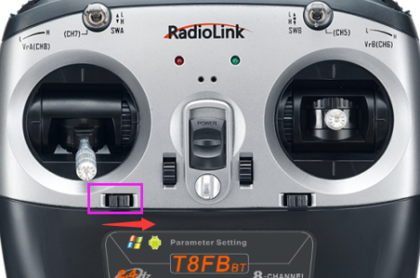
The back part of T8FB:
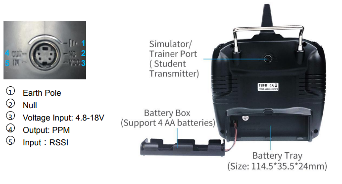
1.2.4 Transmitter Battery
The working voltage of T8FB is 4.8V-18V, and the low voltage alarm is self-adaptive. For example: if you are using a 2S lithium battery to power T8FB, T8FB will send out a beep sound alarm when the battery voltage reaches 7.3V automatically, with no separate settings.
Power supply battery selection for T8FB: You can use the standard battery box with 4 pieces AA batteries for power supply, or use lithium batteries (2S/3S/4S) to supply power.
Note:
- When inserting the battery, please make sure the positive and negative poles are inserted correctly. Since the T8FB has anti-reverse insertion function, if the positive and negative poles are inserted reversely, T8FB will not be powered on, and the T8FB will not be damaged. So please insert the battery correctly when the positive and negative poles are reversed.
(2) When 4 AA batteries are used to supply power to T8FB, if there is a DD sound warning once T8FB is powered on, the battery voltage may be lower than the warning voltage, please replace the fully-charged battery.
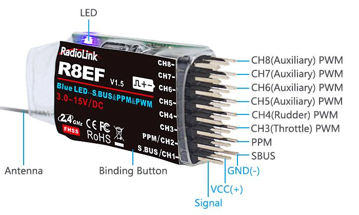
1.3 R8EF Receiver
1.3.1 Receiver Mode and Signal Switch
The standard receiver packed with T8FB is R8EF, an 8-channel receiver with PWM and SBUS/PPM signal output supported.
Signal Working Mode
(1) PWM Working Mode: Receiver indicator is RED with all 8 channels output PWM signal.
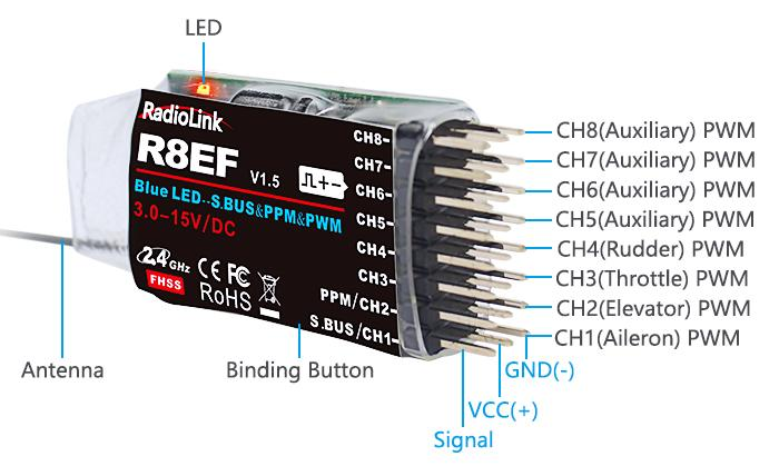
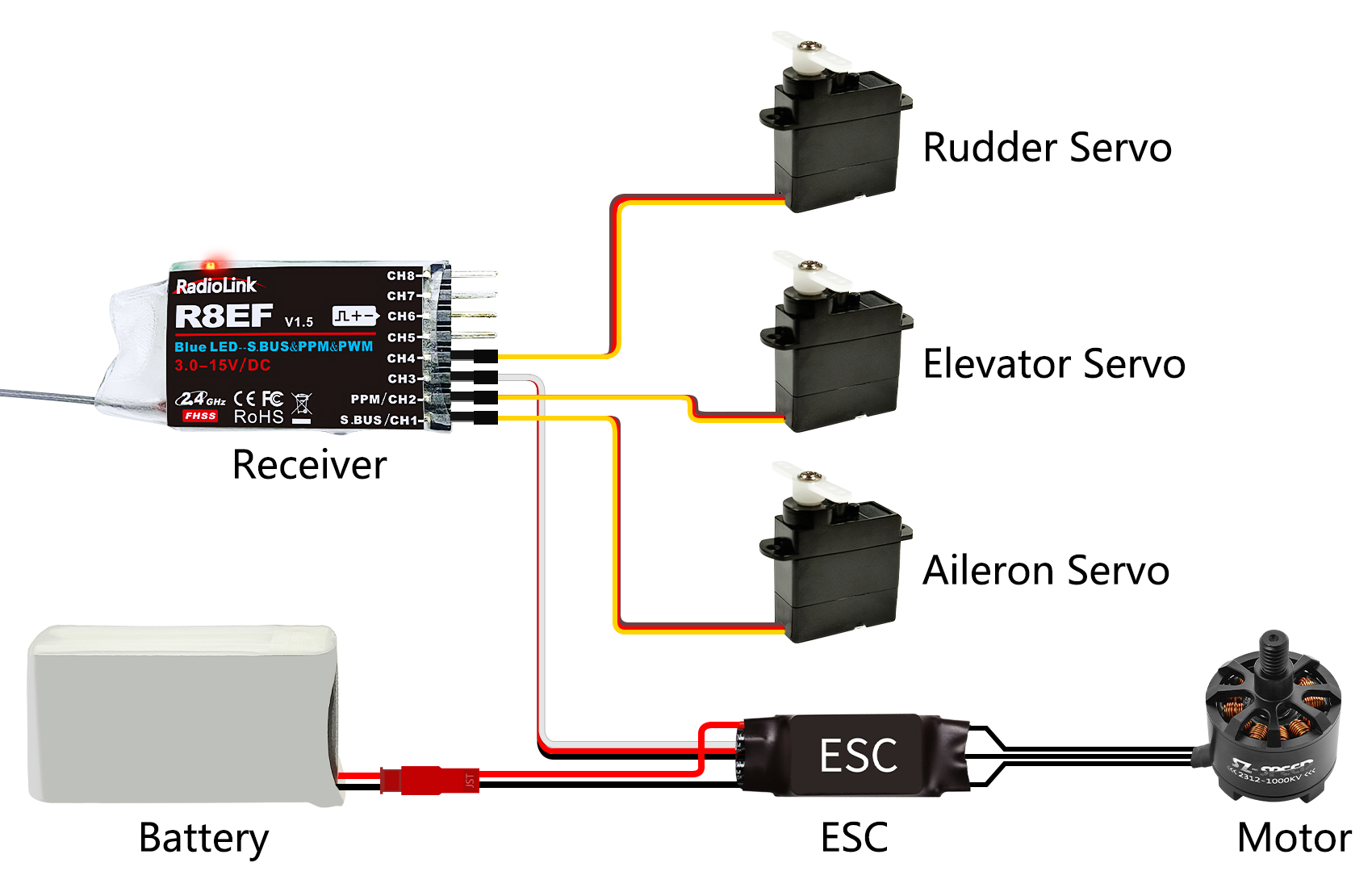
(2) SBUS/PPM Working Mode
Receiver indicator is Blue(Purple) with 8 channels output in total. Channel 1 is SBUS signal, channel 2 PPM signal and channel 3 to 8 PWM signal.
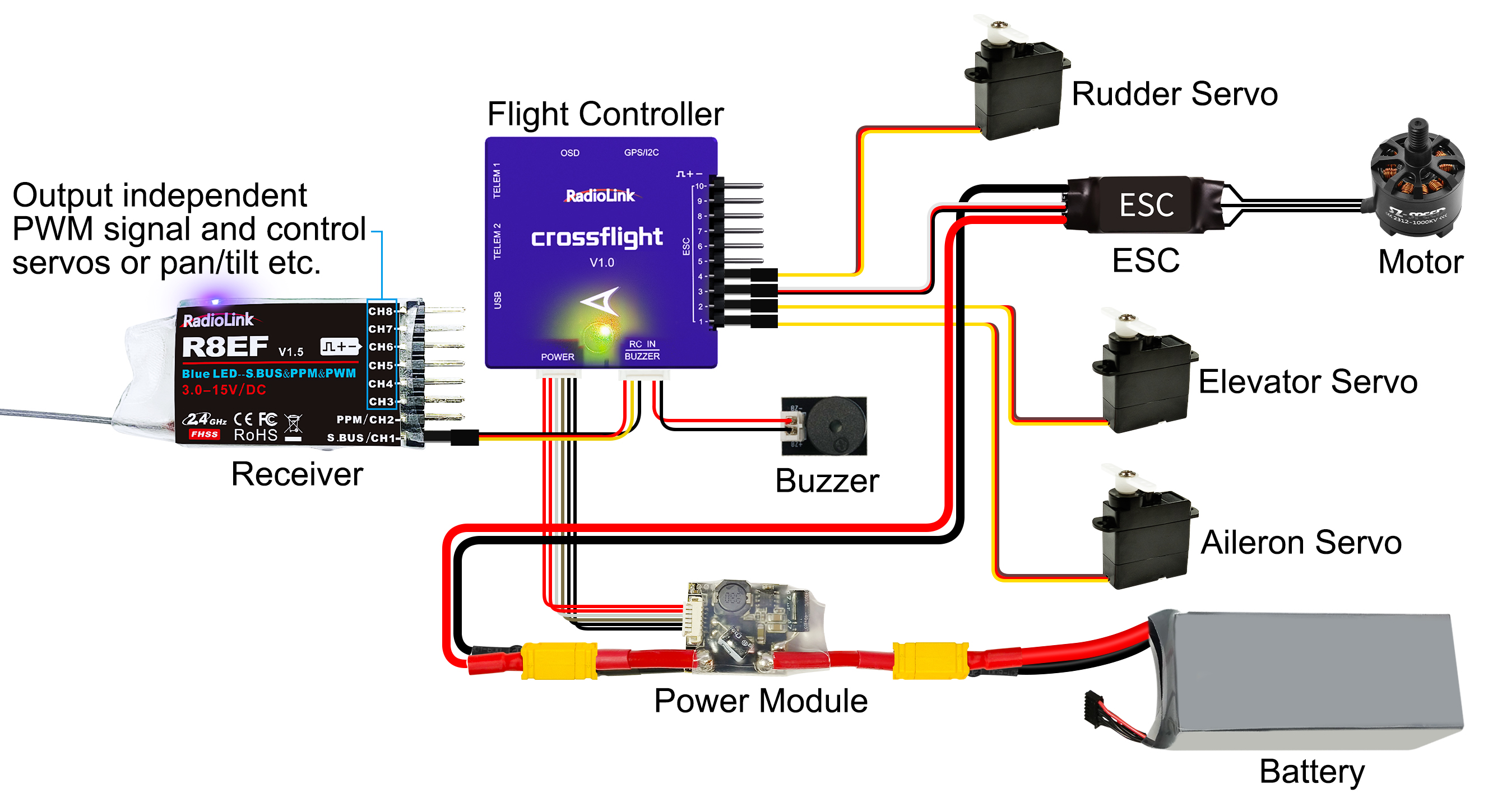
Note: Fixed wing equipped with flight controller is taken as an example.
Signal Switch between SBUS&PPM and PWM
Short press the binding button on the receiver twice within 1 second to switch the SBUS/PPM signal to PWM signal.
1.3.2 Guide of Receiver Install
1) Please test RSSI (Received Signal Strength Indicator) before operating models. For methods on how to test it, please refer to https://www.radiolink.com.cn/troubleshooting_loss_of_control_and_signal_Issues
2) If the antenna of the receiver is damaged, replace it with a new antenna or receiver in time.
3) Keep antennas as straight as possible, or the effective control range will reduce. PS: Generally, the receiver’s antenna is longer than the body of the drone, but also shouldn't break or shrink the antenna into it.
4) Big models may contain metal parts that influence signal emission. In this case, antennas should be positioned on both sides of the model to ensure the best signal status in all circumstances.
5) Antennas should be kept away from metal conductors and carbon fiber at least half inch away and no overbending.
6) Keep antennas away from the motor, ESC, or other possible interference sources.
7) The receiver contains some high-precision electronic components of high-precision. Be careful to avoid strong vibration and high temperature.
8) Special vibration-proof material for R/C, like foam or rubber cloth, is used to pack to protect the receiver. Keeping the receiver in a well-sealed plastic bag can avoid humidity and dust, which would possibly make the receiver out of control. Putting the receiver into a plastic bag can also prevent fuel and residue from entering.
1.3.3 Binding
Every transmitter has a unique ID code. Before using, binding transmitter to receiver on aircraft is a must. When binding is finished, ID code will be stored in the receiver, no need to rebind, unless the receiver is going to work with another transmitter. If you purchase a new compatible receiver, binding needs to be done before using.
Binding steps:
① Put the transmitter and the receiver close to each other in parallel (about 50 centimeters).
② Push the Power Switch to power on T8FB.
③ Power on the R8EF, the LED of R8EF will start flashing slowly.
④ There is a binding button(ID SET) on the side of receiver. Press the button until the LED flashing quickly and release, binding process is ongoing.
⑤ When the LED stops flashing and turns to always on, binding is complete. If not succeed, the LED will keep flashing slowly to notify, repeat the above steps.
Check the binding tutorial here:
Chapter 2 Parameters Setup APP
2.1 Mobile phone APP
2.1.1 Mobile Phone APP Installation
Android APP:

Visit https://www.radiolink.com.cn/t8fb_bt_app to download the android APP to setup T8FB parameters by Bluetooth connection.
NOTE: The APP will not collect any user's information, you can even use this APP without Internet connecting. The APP asked for Location Permission only used for connecting and telemetry function.
Apple APP: Search Radiolink in Apple store (See picture on the right) and then click it to download.
2.1.2 Mobile Phone APP Connection
Connection of both Android APP and Apple APP to T8FB are the same as below:
① When the installation of parameter setup APP is complete, push the power button to turn on T8FB.
② Click to enter the APP, a message will pop out to ask for permission to turn on the Bluetooth function.
③ Click CONNECT on the top left of interface, a list of devices will pop out for selection.
④ Select RadioLink device, the two LED indicators at rightmost will flash with DD sounds.
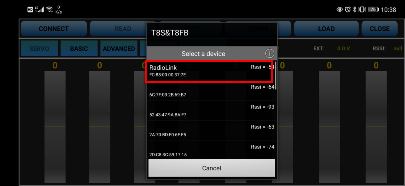
⑤ Push any of the trimmer buttons to stop the DD sounds and the servo range will display on the APP, meaning connection between the APP and T8FB succeed.
Note:
If there is no servo range display in APP, it means the connection is unsuccessful and you need to reconnect.
If you cannot find the Bluetooth device with the name “RadioLink” after clicking “CONNECT”. Please check whether the “Location Information” of your phone is turned on, if not, please open the “Location Information”;
If the “Location Information” is on, but you still can’t find “RadioLink Bluetooth device”. Please open the application in the phone --settings-application management--T8S&T8FB permissions--location information, change the location information from “only allowed during use” to “Prohibited”, and then change to “allowed only during use”again.
If all the steps above have finished, but the mobile phone parameter setup APP still cannot connect the transmitter success, please download the version V603.
2.1.3 Mobile Phone APP Parameters Setup Menu
Parameters setup of both Android APP and Apple APP are the same.
The setup menu includes: SERVO, BASIC, ADVANCE, PROG.MIX. After click PROG.MIX, there are 4 PROG.MIX setting, SYSTEM, TH/CURE, DR/CURE, RESET. For detailed setting method, please refer to 3.2 Basic Menu.
There are function keys on the top of the parameter setup interface.
(DIS)CONNECT: When the APP is opened and the T8FB is powered on, click CONNECT, and a list of Bluetooth devices will pop out and select the RadioLink device to make connection. The two LED at the rightmost will flash with DD sounds, press any of the trimmer buttons to stop the DD sounds and the servo range will display on the APP. If fails, press DISCONNECT and CONNECT again.
READ: Click READ, two short D sounds will be heard and the APP starts reading the data in T8FB. Every time the APP is reopened, the data displayed is the initial default value. If the parameters are modified, you need to click to “READ” again to display the modified data.
WRITE: Click “WRITE” and three slow D sounds mean the modified data have been written successfully. If no D sound means written failure, please reconnect T8FB to the APP and re-write.
Note:
- Click “WRITE” each time parameter is modified to make sure it’s well input to the T8FB. The modified parameters won’t be saved if “WRITE” is not clicked.
- If you want restore the factory default settings, please reconnect to the APP, and click "Reset".
LOAD(Load/New/Delete model):
There are three functions can be set by press LOAD, that is load or select model data that have set already and add a new model.
① Load model: A tooltip will pop out when Click LOAD, and then click “SELECT” to load the model data from this tooltip. If there is no model data have stored successfully, the tooltip will show blank.
② Create new model: Click "NEW" and name the new model, for example, “RacingDrone1”. Click "YES" to save the new model’s name, then click the model’s name, the gray title bar on the top of tooltip will change to RacingDrone1, click “SELECT” to select the model’s name, and then set up all the parameters depends on your drone, click “STORE” to save the settings, “/mode/RacingDrone1.txt” pop out means the new model have set successful.
③Delete model: choose a model’s name from the tooltip, for example, still the “RacingDrone1”, the gray title bar on the top of tooltip will change to RacingDrone1, then click “DELECT”, an alert box will pop out, click “YES” to delete the model data.
STORE: Click to save the APP data as a file in the mobile. T8FB support unlimited number of model data to store, and easy to search in the phone. If the new file created is forgotten to rename, but STORE as Model-New, the data in this file will be cleaned automatically when trying to create another new file sharing the same file name.
Note: Each interface can display the transmitter voltage, receiver voltage, RSSI signal strength value, power battery voltage telemetry (when using R8FG, R7FG, R8F, R8XM receivers with telemetry function)
CLOSE: Click “CLOSE” to exist the APP.
2.2 Software APP on Computer
2.2.1 Software APP Installation on Computer
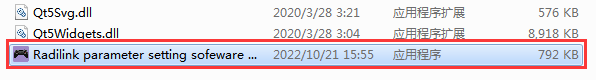
Go to the official website https://www.radiolink.com/t8fb_bt_app to download the computer software APP, and run the program below.
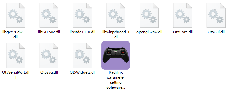
If it’s your first time to use computer parameter APP, you need to install the driver before using it. Please click the link below to download and install driver: http://www.radiolink.com.cn/firmware/transmitter/T8FB(BT)/
or contact us by email at: after_service@radiolink.com.cn
2.2.2 Software APP Connection on Computer
After the driver is installed, T8FB transmitter can connect to computer parameter software.
1) Turn on T8FB transmitter, and connect it to the computer with a USB data cable.
2) Open the parameter software in the downloaded file. Choose Port Number (The COM port of different computers will be different), click OPEN to connect.
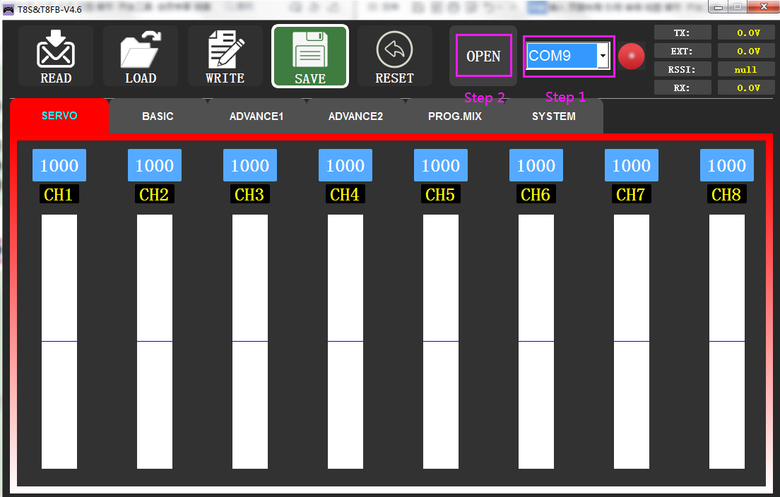
Note: If the driver is installed normally, but the COM port connected to T8FB cannot be detected, you could try another USB data cable. Do not use USB charging cable.
3) T8FB will make DD sounds, press any of the trimmer buttons to stop the DD sounds.
READ: Click READ, two short D sounds will be heard and the APP starts reading the data in T8FB. Every time the APP is reopened, the data displayed is the initial default value. If the parameters are modified, you need to click to “READ” again to display the modified data.
WRITE: Click “WRITE” and three slow D sounds mean the modified data have been written successfully. If no D sound means update failure, please reconnect T8FB to the APP and re-write. Click “WRITE” each time parameter is modified to make sure it’s well input to the T8FB.
* After modifying the parameters, please click to write data, otherwise the modification will be invalid.
* If you want to restore the factory default settings, you can click "Factory Settings".
LOAD: Click LOAD and a pop out of ‘Model Select’ will display. If there is no successfully stored data, there will be no display. Besides, user also can create a new file or select among the saved files.
SAVE: Click to save the APP data as a file in the computer.
Note: Each interface can display the transmitter voltage, receiver voltage, RSSI value, and telemetry battery voltage (Telemetry function is available when using R8FG, R7FG, R8F, R8XM receivers ).
Chapter 3 Function Setup Menu on APP
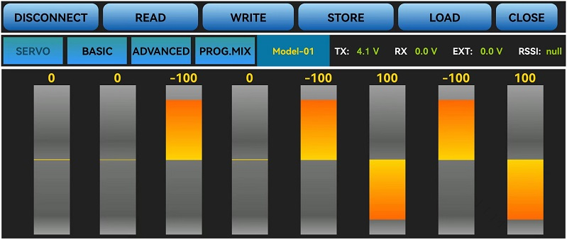
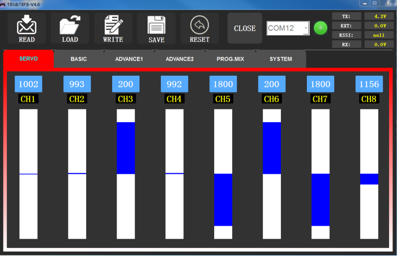
3.1SERVO Menu
The 8 rectangles show the CH1-CH8 servos range instantly (4 basic channels and 4 auxiliary channels) from left to right. CH1--Aileron, CH2--Elevator, CH3--Throttle, CH4--Rudder, CH5 to CH8--Auxiliary channels.
There is a real-time display when you are toggle any channel switch, it is suitable for set up complex mix control functions.
The interface of parameter setup APP on phone.
The interface of parameter setup software on computer.
3.2 BASIC Menu
3.2.1 REVERSE
This function is to change the direction of the servo in response to the remote controller input. Make sure to check all servos move to the correct direction as desired under control.
Note: If the programmable mix control function is used to control several servos for fixed wing/gliders, e.g. V-TAIL mix control, make sure to set the phase in advance to avoid possible confusion.
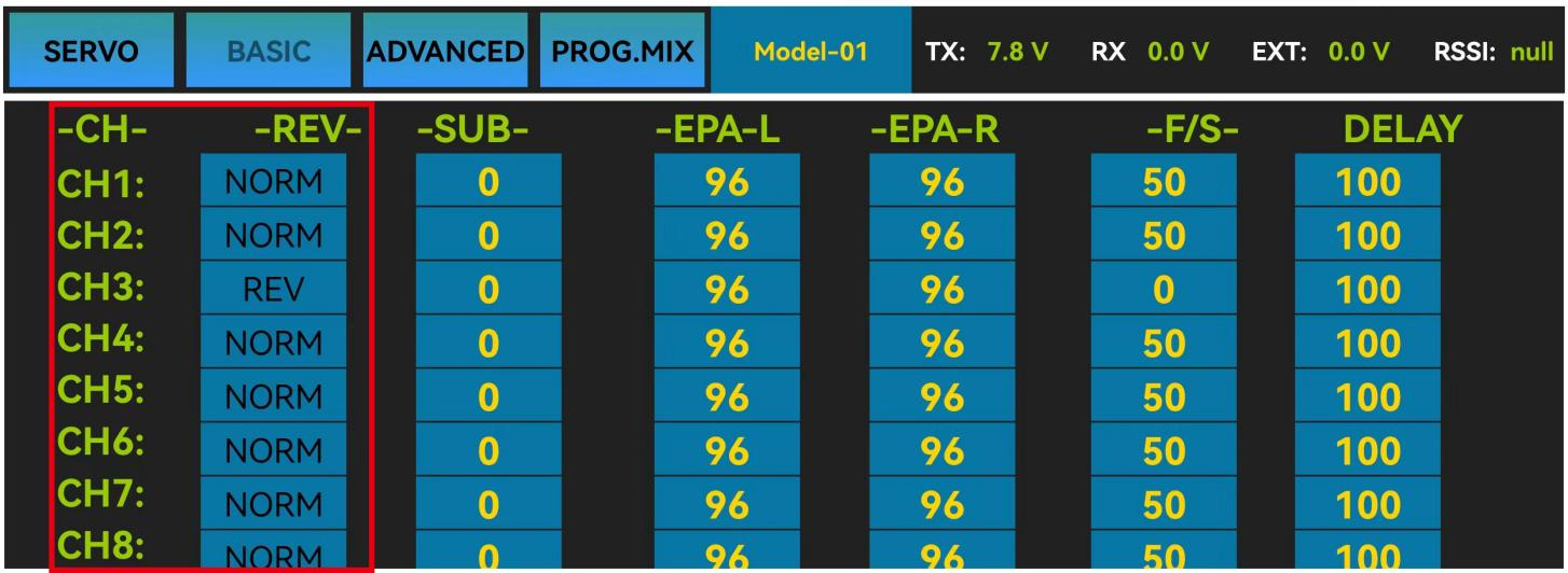
The interface of the parameter setup APP on the phone.
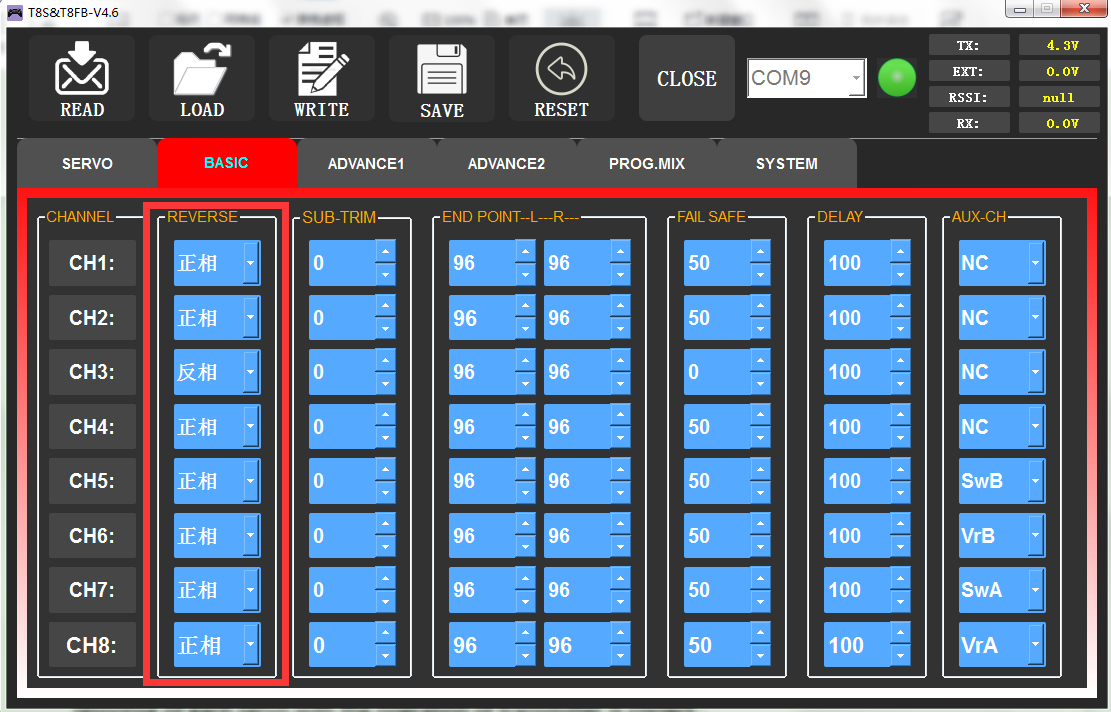
The interface of the parameter setup software on a computer.
After changing the channel phase, please check the control of the corresponding channel on the model, to make sure the response direction of the channel is correct. Make sure that the response of each servo with the operation of transmitter is correct.
3.2.2 SUB-TRIM
Makes small changes or corrections to the neutral position of each servo. The default is 0 setting by factory setting. That is, no SUB-TRIM. The range is from -100 to +100 and can be modified with actual need.
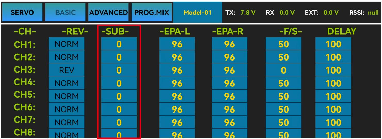
The interface of parameter setup APP on phone.
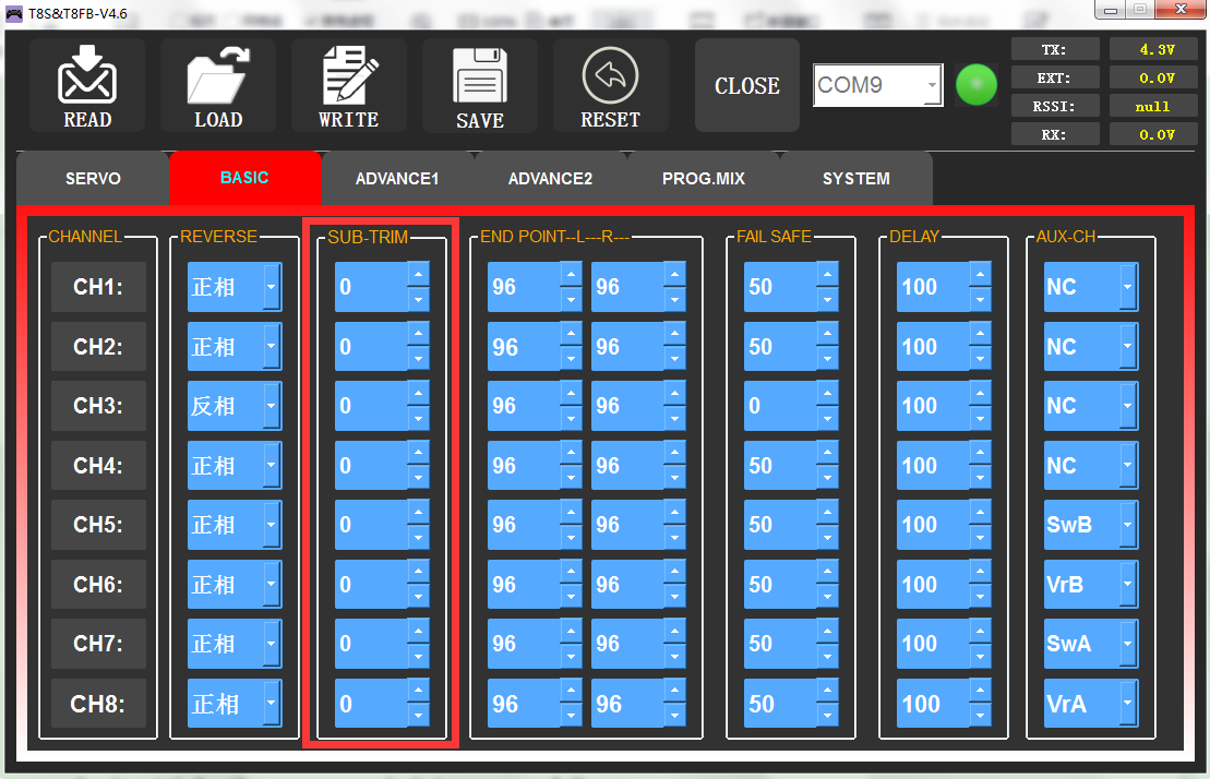
The interface of parameter setup software on computer.
This function is used to set the neutral position of the servo, not to set the servo surface to be horizontal. So, the recommended steps are as follows:
• Zero out the SUB-TRIM when the servo is not connected to servo surface, and adjust the neutral position of the servo through SUB-TRIM.
• Zero out the SUB-TRIM.
• Mount servo arms and linkages so that the control surface’s neutral is as correct as possible.
• Modify with SUB-TRIM small range value to make fine corrections.
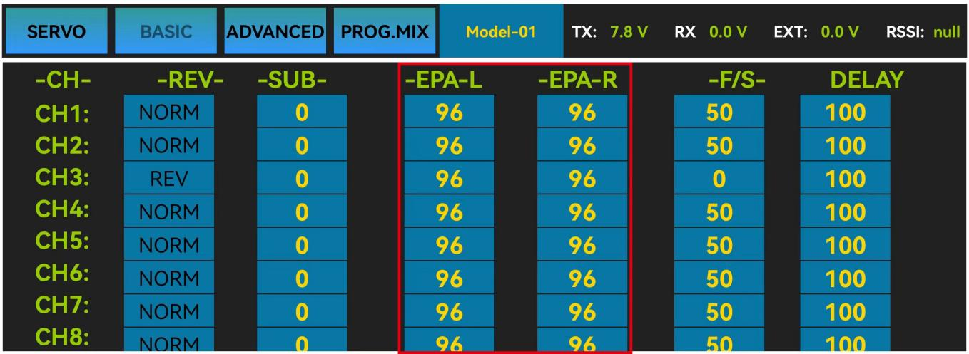
3.2.3 END POINT ADJUSTMENT (EPA)
This function is used to set travel range of the servo connected to the channel.
When setting the model or after the first flight, if you feel that the movement of the model is still relatively small when you move the joystick to the maximum position. You can increase the travel range percentage of the corresponding channel of the servo (the maximum can be adjusted to 120, The default is 96). EPA-L and EPA-R respectively represent the travel range on two sides of the neutral point. You can choose the side you want to modify to adjust travel range percentage.
The interface of parameter setup APP on phone.
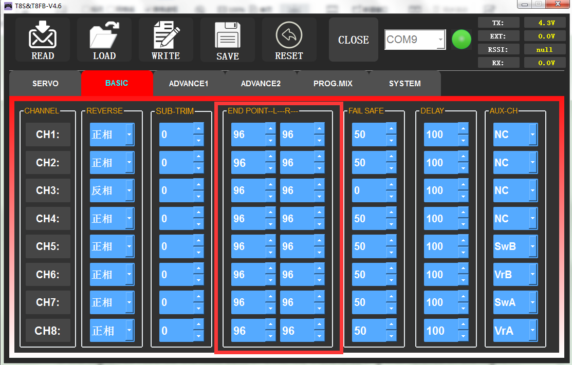
The interface of parameter setup software on computer.
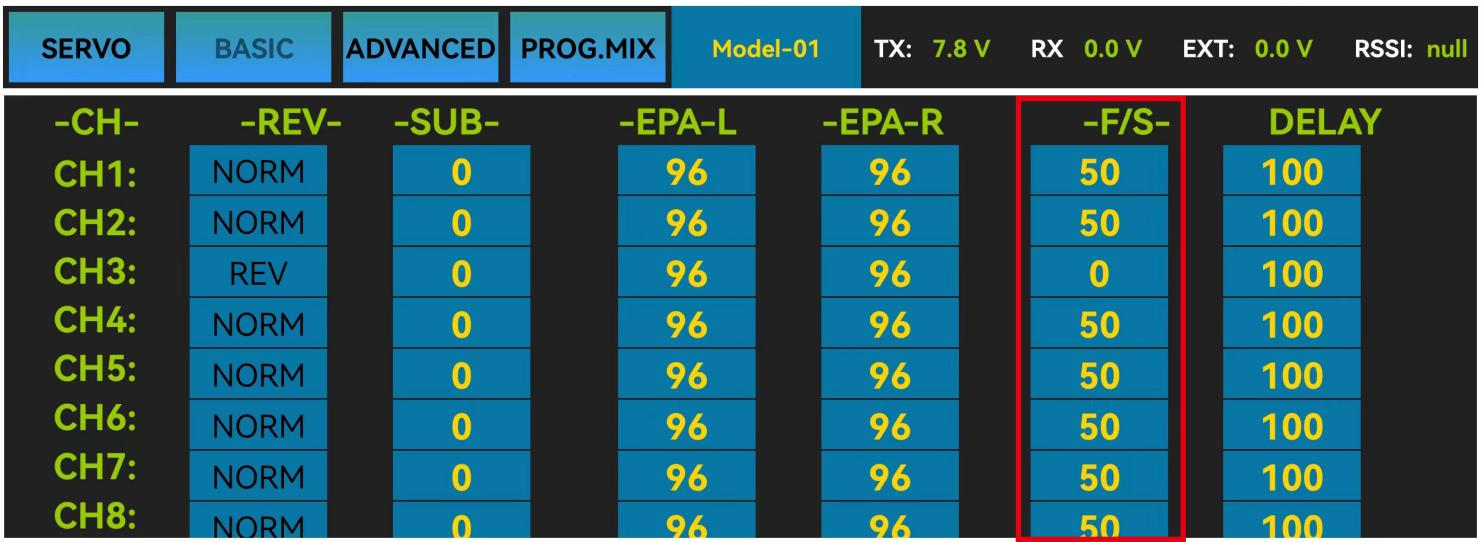
3.2.4 FAIL SAFE (F/S)
If the flight has reached the limit control distance, there is strong interference in the flight area, there are obstacles between the transmitter and the receiver, or T8FB low voltage it will cause loss of control. At this time, you can set the Fail-Safe, so that the model can maintain working at the F/S value you set after loss of control. F/S needs to be set in advance. Each channel can be set independently.
According to your needs, set the servo travel range output by the channel. After setting it, the receiver will continue to output the servo travel range according to the value you set when the receiver loses the control of transmitter.
The interface of parameter setup APP on phone.
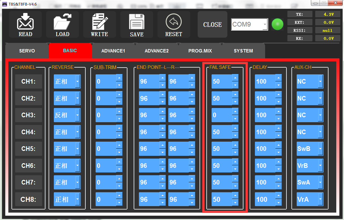
The interface of the parameter setup software on a computer.
Note:
- The setting of the throttle F/S also applies to the low battery voltage. F/S value 0 means throttle stick at the lowest point while 50 means at the central point.
- The F/S (Fail-safe) function can be used in certain competitions to ensure safe landing of the model prior to flying away and dropping. Besides, it can also be used make all servos neutral to maximize the flight time.
3.2.5 DELAY
Adjusts the synchronous ratio between the servos position and the actual operation. The default value is 100 by factory setting meaning no delay.
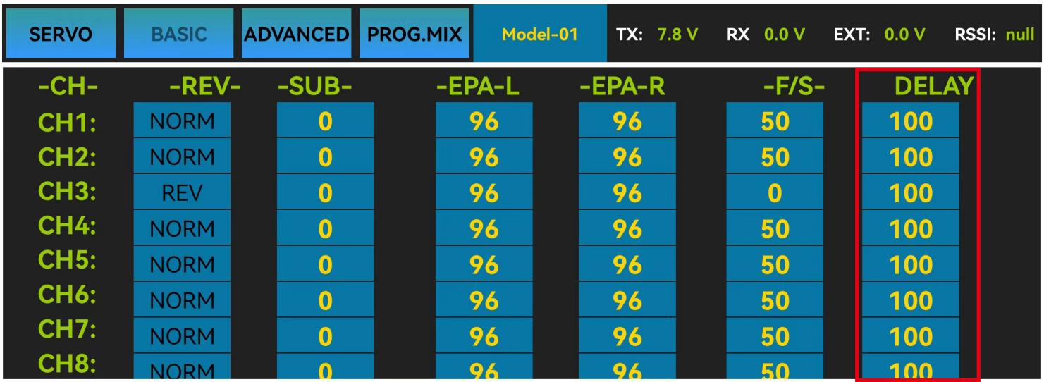
The interface of parameter setup APP on phone.
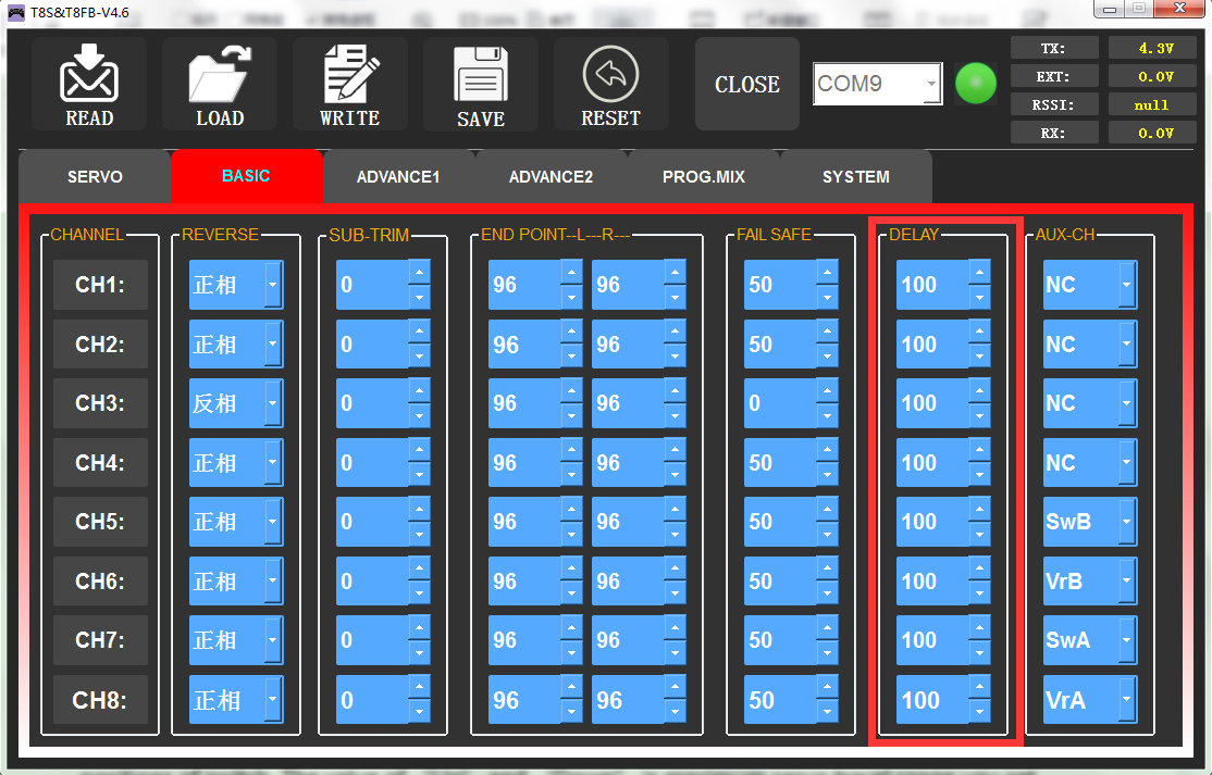
The interface of the parameter setup software on a computer.
3.3 ADVANCED Menu
3.3.1 D/R (Dual Rate)
The model can be controlled to work on different servo travel range by a switch. Before using this function, set the state of “Mix” from “INH” to “ON”.CH1/2/3/4 can be chosen to set separately. the switch can be set to SWA or SWB. “Up” and “Down” correspond to the positions of switch. The value of “Up” and “Down” is maximum servo travel range you set.
Channels 1 to 4 can be set for different servo travel range both individually and at the same time.
When setting one channel for different servo travel range, click “WRITE” after setting D/R value for the corresponding channel. When setting 4 channels for different servo travel range at the same time, click “WRITE” after setting D/R value for each channel. For example: after setting D/R value of channel 1, click “WRITE” to save the settings, and then switch the channel to “CH2”. Set D/R value of channel 2, and then click “WRITE” to save the settings. Repeat this step for channel 3 and channel 4.
DR/CURE: It’s an index. When it is not set, the value defaults to 0, and the output servo travel range of the corresponding channel will be output in proportion to the move of the joystick. The value can be set from -100% to +100%. The change of the index will not change the maximum and minimum servo travel range. When controlling the aircraft, the index setting value is usually negative.
- When the index is a negative value, the greater the negative value, the lower the sensitivity of the joystick in the neutral position and the higher the sensitivity at both ends position.
- When the index is a positive value, the greater the positive value, the higher the sensitivity of the joystick in the neutral position, and the lower the sensitivity at both ends position.
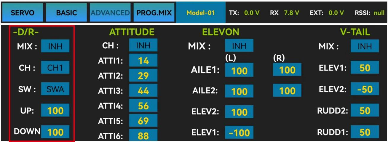
The interface of the parameter setup APP on the phone.
The interface of the parameter setup software on a computer.
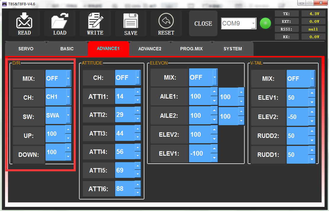
3.3.2 ATTITUDE
Select the preferred channel from CH5 through CH8. CH5 is always the default switch to change attitude when connect to flight controller PIXHAWK/MINI PIX/crossflight/APM/TURBO PIX with multi-rotor firmware, and CH8 is the default switch with fixed-wing firmware, while CH7 is default when connect to DJI flight controller. For the default channel to switch attitudes, please refer to the flight controller user manual.
Note: After open the “Attitude” function, the switch of CH5 and CH7 will be used by default to control the output of the “attitude channel”.
The values behind each channel means different control percentage output different control signals. The default values of T8FB of each attitude is corresponding to the values of flight controller PIXHAWK/MINI PIX/crossflight/APM/TURBO PIX. That is, when the above flight controllers are used with T8FB, attitude can be selected on the Mission Planner and no need to setup specific parameter.
Different values can be set for ATTI 1 to ATTI 6. Then you can change the flight attitude by press CH5/CH7.
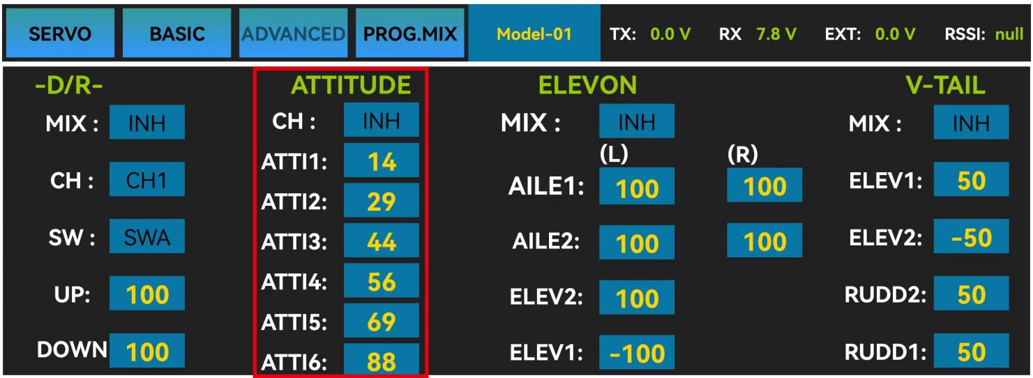
The interface of parameter setup APP on phone.
The interface of parameter setup software on computer.
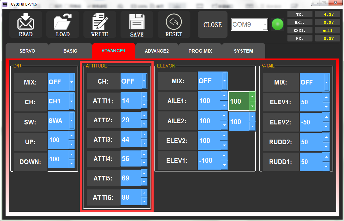
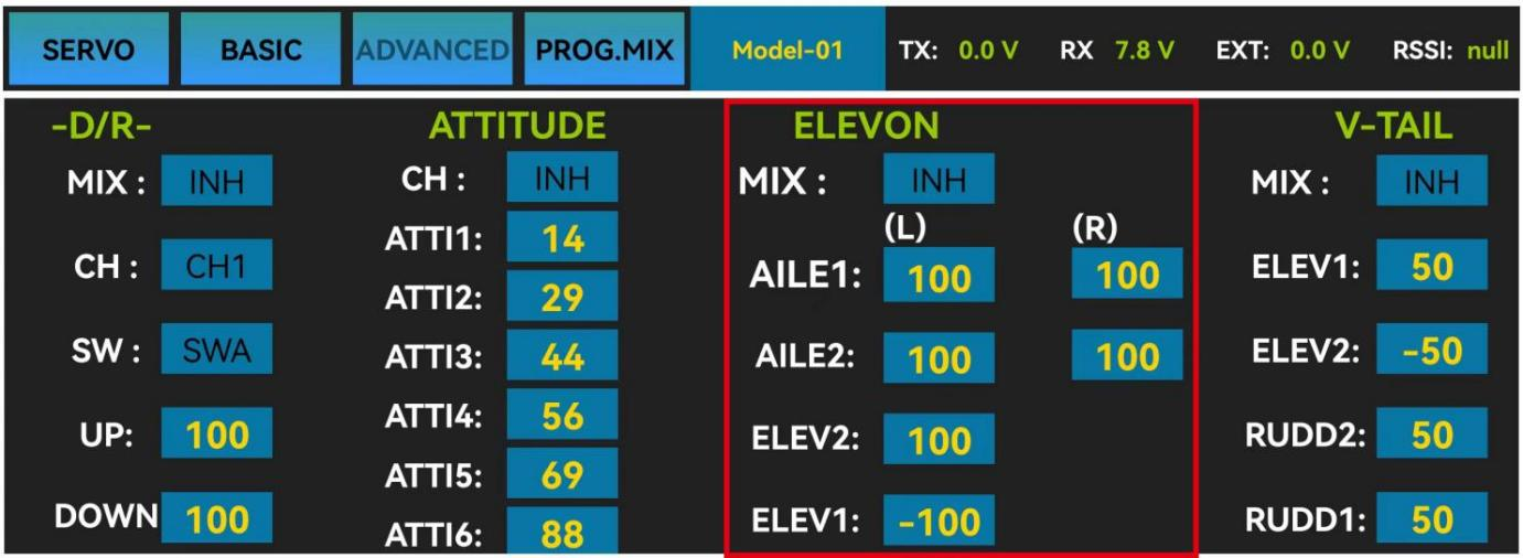
3.3.3 ELEVON
“Elevator mix” is also known as “delta wing mix”. It is often used for delta wing aircraft. Two servos can control two servos surfaces that on the left and right sides of the aircraft separately, and operate aileron function and elevator function.
When “MIX” is set from “INH” to “ON”, the “AILE” and “ELEV” function is turned on. When this function is turned on, then both CH 1 and CH2 will respond, and servo travel range can be adjusted individually.
- AILE 1 and ELEV 2 correspond to the response rate of channel 1 when performing aileron operation and elevator operation.
- AILE 2 and ELEV 1 correspond to the response rate of channel 2 when performing aileron operation and elevator operation.
The specific value is the amount of servo travel range when the corresponding channel performs the aileron or elevator operation. Positive and negative values represent different directions of movement.
The interface of parameter setup APP on phone.
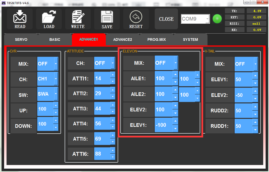
The interface of parameter setup software on computer.
3.3.4 V-TAIL
V-TAIL used for fixed wing with v-tail. Two servos can control two servos surfaces that on the left and right sides of the aircraft separately, and operate aileron function and elevator function.
When “MIX” is set from “INH” to “ON”, the “ELEV “and “RUDD “function is turned on. When this function is turned on, then both CH2 and CH4 will respond, and servo travel range can be adjusted individually.
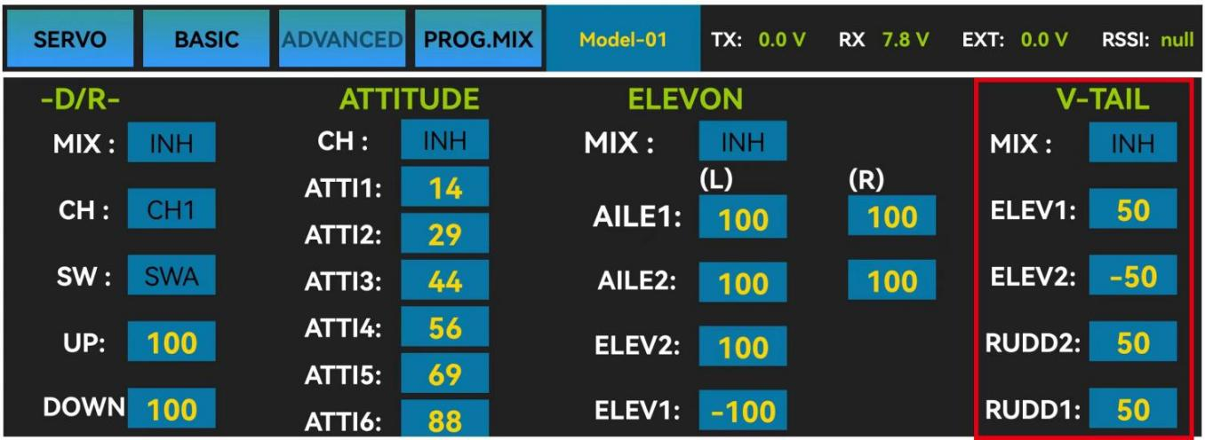
The interface of the parameter setup APP on phone
ELEV 1 and RUDD 2 correspond to the response rate of channel 2 when performing elevator operation and rudder operation.
ELEV 2 and RUDD 1 correspond to the response rate of channel 4 when performing elevator operation and rudder operation.
The specific value is the amount of servo travel range when the corresponding channel performs the elevator or rudder operation. Positive and negative values represent different directions of movement.
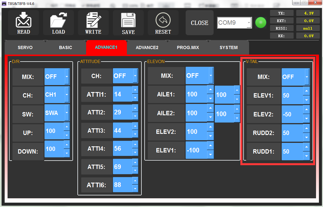
The interface of the parameter setup software on computer
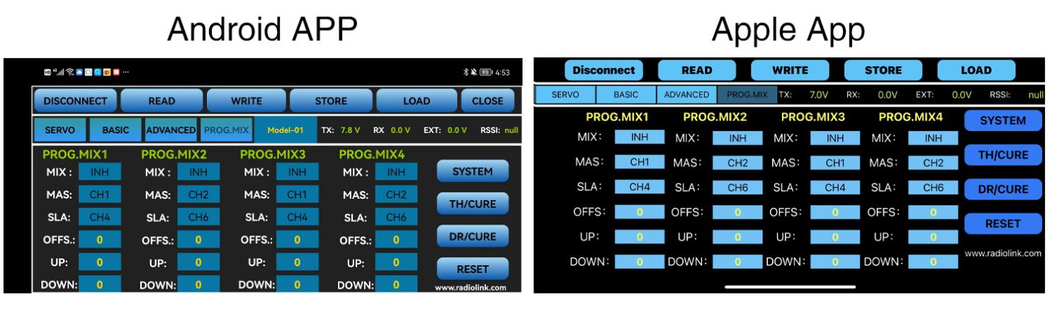
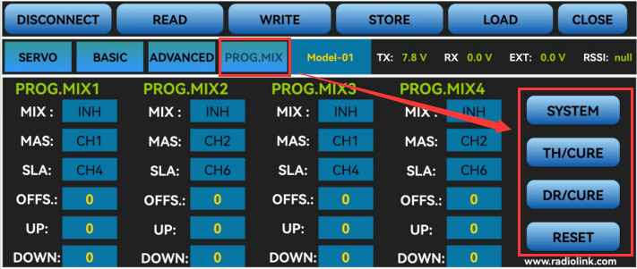
3.4 PROG.MIX Menu
3.4.1 PROG.MIX
Programmable mix control is custom mix settings, which can independently select the master channel and slave channel. It is often used to compensate for the attitude changes of the aircraft.
4 groups of programmable mix control can be set.
Programmable mixing controls are to:
① Diversify attitude changes of aircraft (e.g. Rolling to realize when rudder is commanded);
② Control a certain axis with two or more servos (e.g. 2 rudder servos);
③ Correct special movement automatically (e.g. Lower FLAP and ELEVATOR servos at the same time);
④ Control the second channel to respond to the movement of the first channel (e.g. Increase smoke oil to respond to high speed, but only when the smoke switch is activated);
⑤ Turn off the main control under certain circumstances (e.g. For dual-engine aircraft, turn off a motor or speed up/down one motor to assist rudder to turn).
MAS: Master channel. Other channels need to cooperate with movements of the master channels.
SLA: Slave channel. Many mix controls are controlled by one master channel.
You can turn the “MIX” from “INH” to “ON”, and set master channel, slave channel. Set “UP” and “DOWN” to the same value. This value determines the servo travel range and movement direction of slave channel.
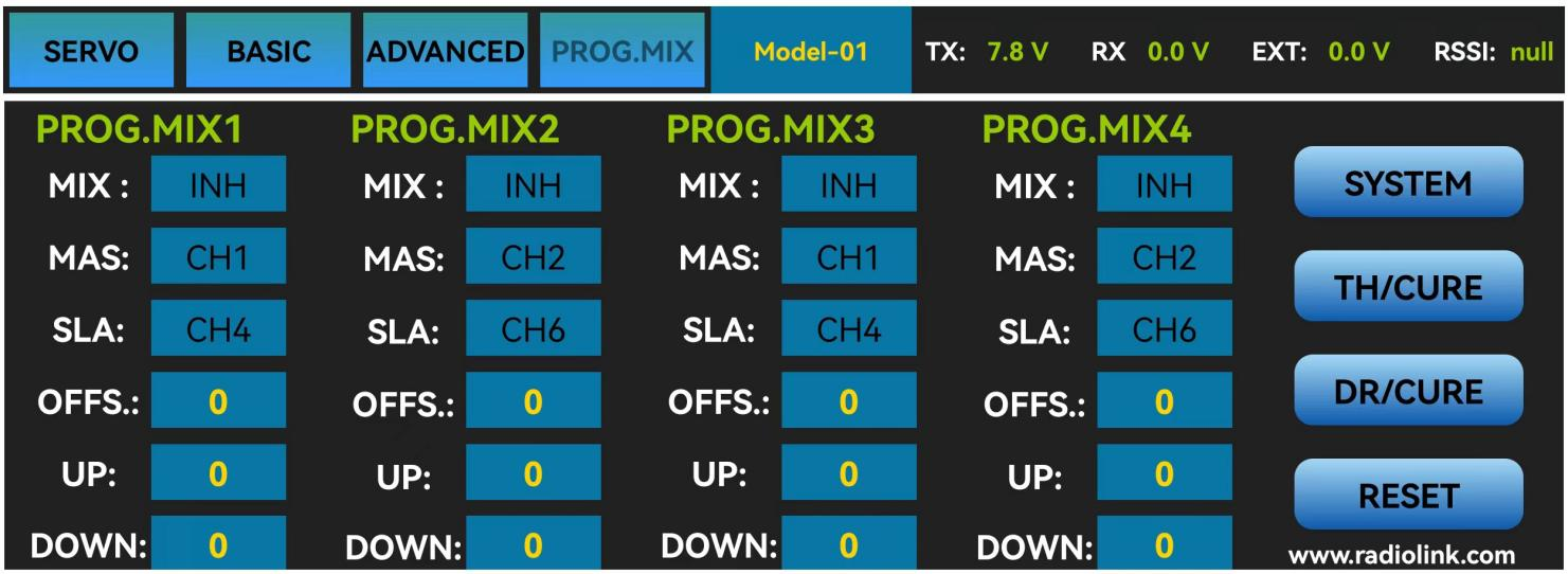
The interface of the parameter setup APP on the phone.
There are 4 groups of programmable mix control that can be set in the mobile phone APP.
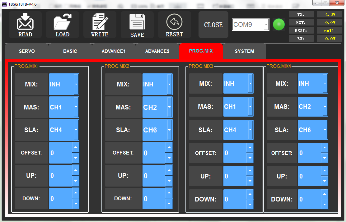
The interface of the parameter setup software on a computer. 4 groups of programmable mix control can be set in the computer parameter software.
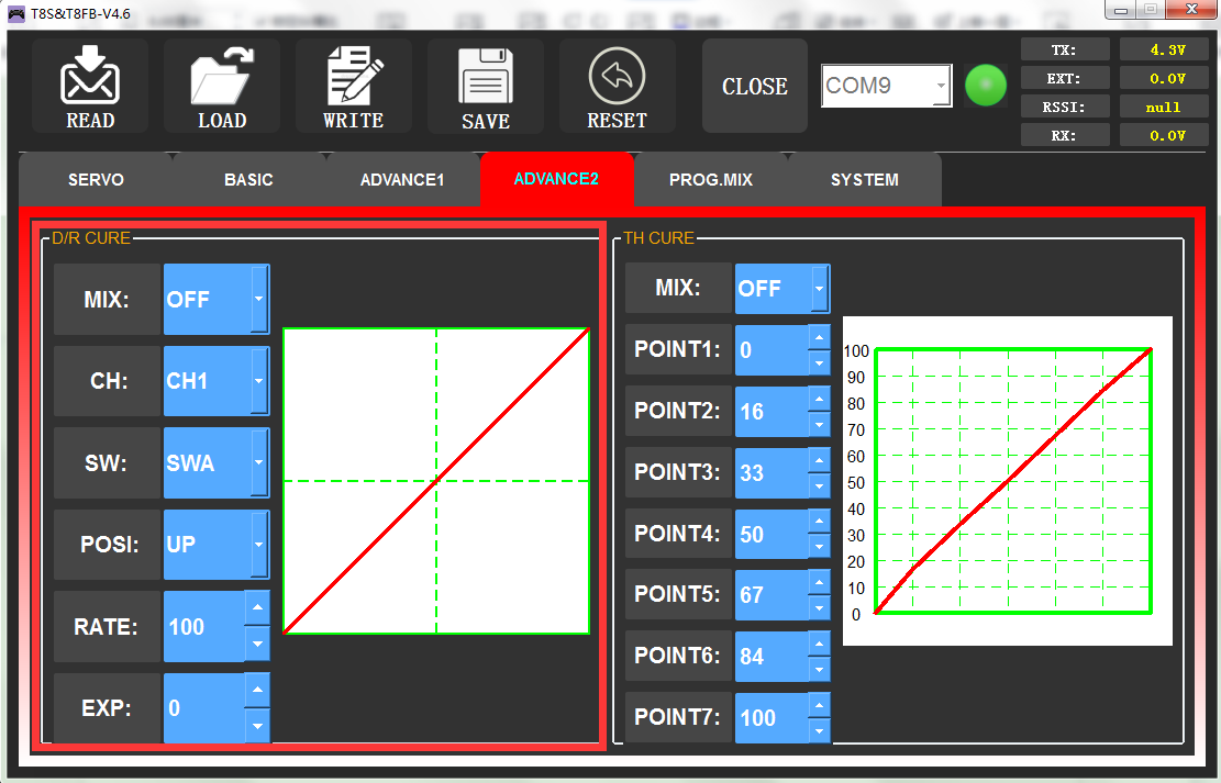
3.4.2 TH/CURE
The throttle curve (TH/CURE) is the set output travel by throttle. It is to coordinate the motor response and the throttle operation. The horizontal ordinate is the joystick position while the vertical ordinate is the throttle output.
When “TH-SW” is set from “OFF” to “ON”, the throttle curve function is turned on. Adjust the value of 7 points. The adjustable range is from 0 to 100. The larger the value it is, the larger the output throttle is when the throttle joystick moves to the corresponding position.
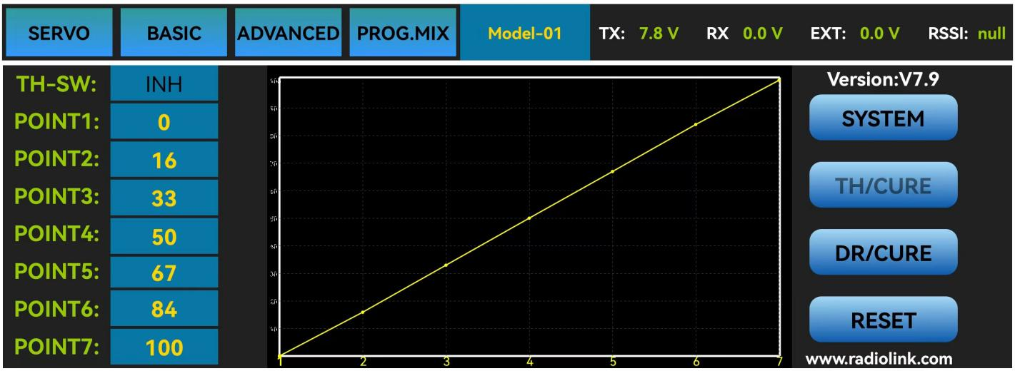
The interface of parameter setup APP on phone
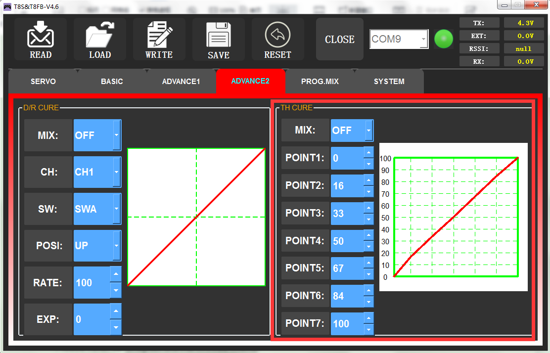
The interface of the parameter setup software on a computer
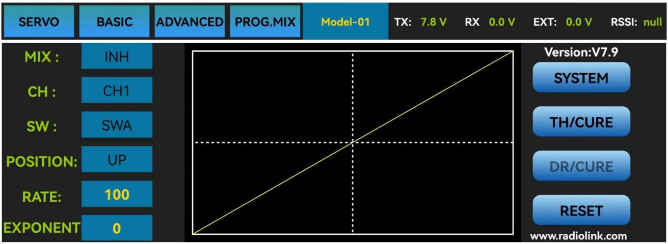
3.4.3 DR/CURE
Please refer to Chapter 3.3 ADVANCE Menu.
3.4.4 SYSTEM Menu
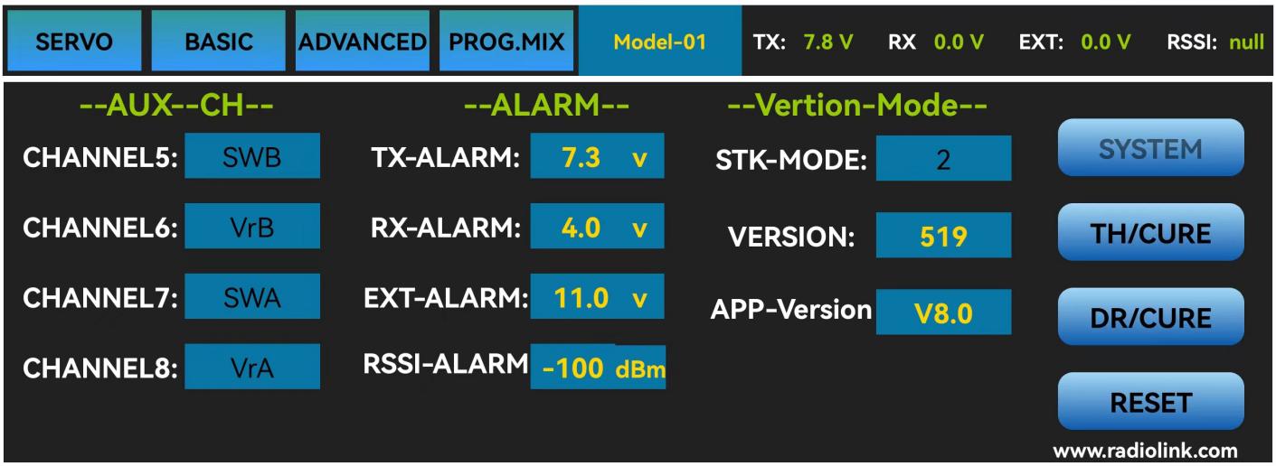
The interface of ”SYSTEM” on the phone
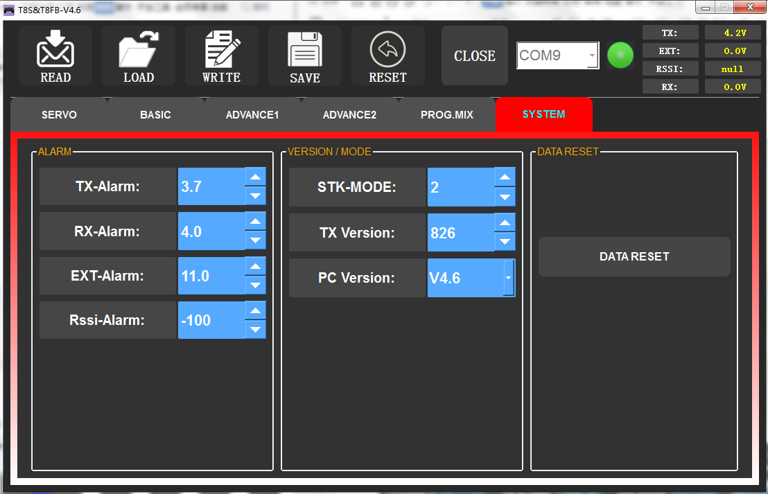
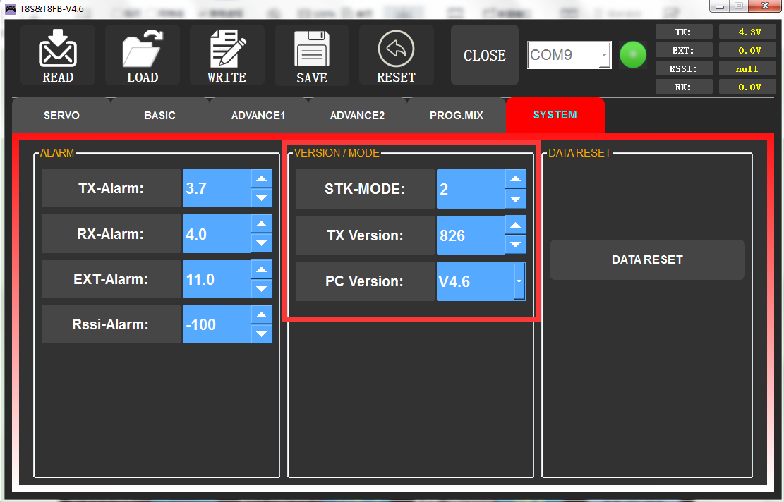
The interface of ”SYSTEM” on the computer
3.4.4.1 AUX.CH
The CH1/2/3/4 of the T8FB transmitter are 4 basic channels, and CH5/6/7/8 are auxiliary channels. The switch of the basic channel cannot be modified. But different switches can do some auxiliary functions by setting CH5/6/7/8, such as control the opening and closing of the bait hopper, control whether the machine releases smoke or not etc.
Each auxiliary channel can be customized with one of three-way switch, toggle-switch or push-switch. Any one of three-way switch, toggle-switch or push-switch can also be set to control different channels.
And the final effect can be seen on the “SERVO MENU” interface.
Note: If you flip any switch and two channels will change, please check whether the two auxiliary channels are set to the same switch.
Click the auxiliary function of CH5/6/7/8, there will be five options of “SWA”, “SWB”, “VrA”, “VrB” and “NULL” for selection.” NULL “means no switch control.
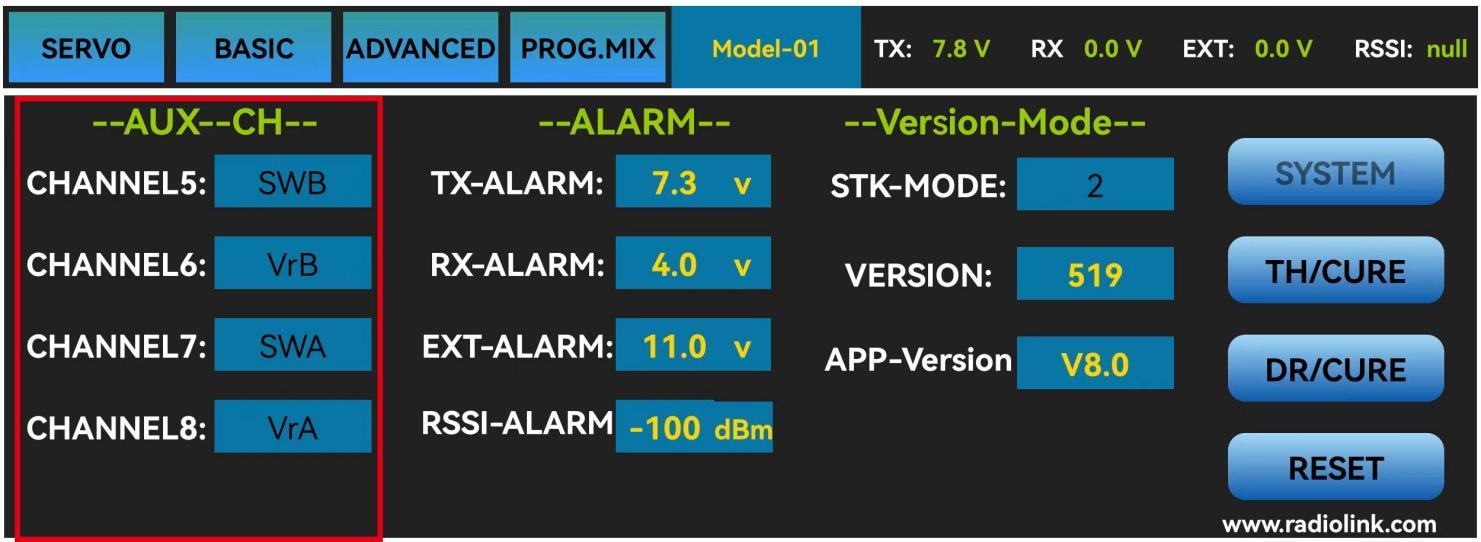
The interface of parameter setup APP on phone.
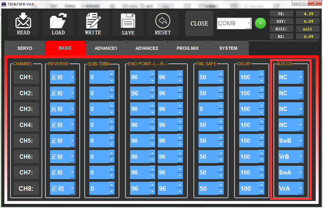
The interface of the parameter setup software on the computer.
3.4.4.2 ALARM
TX-ALARM
The default low voltage value of transmitter is automatically set according to the battery used. For 2S lipo battery, it is 7.3V. For 3S lipo battery, it is 11V. For 4 AA batteries with 1.5V, the default low battery alarm voltage is 5V. When the transmitter voltage is lower than the alarm value, T8FB will continuously make “D” sounds to warn.
RX-ALARM
The default low voltage value of receiver is automatically set 4V by default, and small adjustments are also supported. When the compatible receiver supports receiver voltage telemetry and the receiver voltage is lower than the value set, T8FB will make “DDDDD” sounds as a unit to warn. (Note: R8EF receiver does not support receiver voltage telemetry)
EXT-ALARM
To return the model voltage, RadioLink receivers of telemetry functions R8XM, R8FG, R7FG or R8F should be used. Small adjustments are also supported. When the model voltage goes lower than the set value, T8FB will make “DDD” sounds as a unit to warn. We suggest that 7.4V set for 2S lithium battery, 11.1V set for 3S lithium battery, 14.8V set for 4S lithium battery.
RSSI-ALARM
The default signal strength alarm value of the T8FB is -100dBm. You can set a reasonable value according to the actual situation to prevent the model from losing control due to weak signal. When the RSSI goes lower than value you set, T8FB will make ”DDDD” sounds as a unit to warn.
The best RSSI-ALM is depends on the control range test at your flying area. For example, you have tested the control distance of your T8FB is 2000 meters at your flying area, and the RSSI shows -86dBm at this time, then you can set the RSSI alarm data is -86dBm.
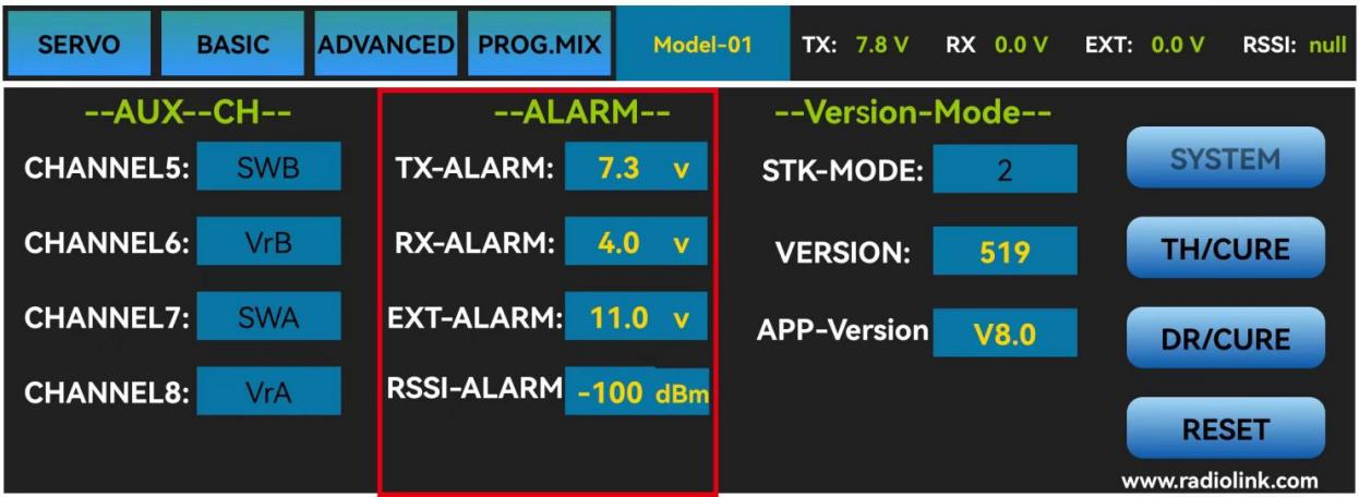
The interface of the parameter setup APP on the phone
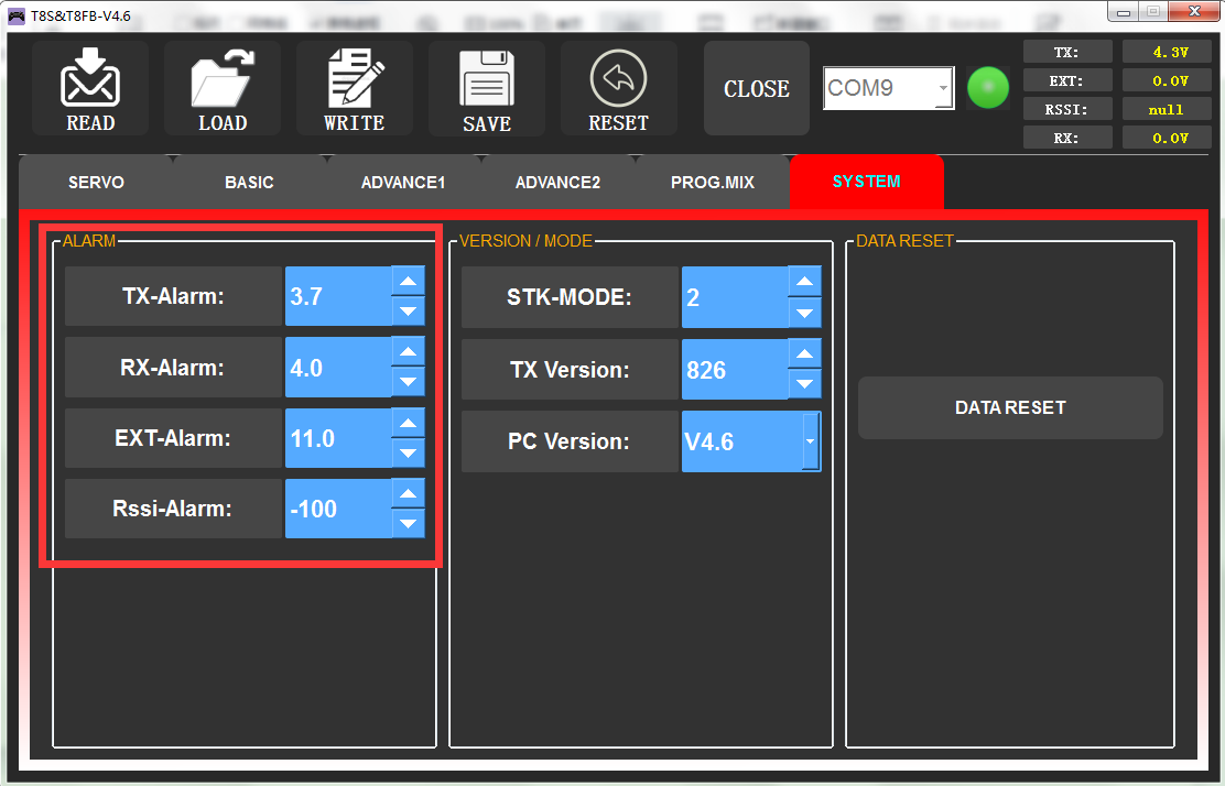
The interface of the parameter setup software on the computer
3.4.4.3 Version MODE
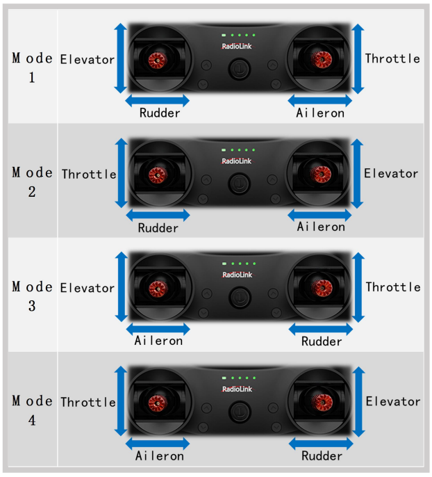
STK-MODE
The T8FB transmitter has 4 STK-MODES, Mode 1 (Japanese hand), Mode 2 (American hand), Mode 3 (Chinese hand), and Mode 4 (others). The factory default of the T8FB transmitter is mode 1 or mode 2, you can also modify it according to your habits.
Mode 1: left joystick-Rudder and Elevator; right joystick-Aileron and Throttle
Mode 2: left joystick-Rudder and Throttle, right joystick-Aileron and Elevator
Mode 3: left joystick-Aileron and Elevator, right joystick-Rudder and Throttle
Mode 4: left joystick- Aileron and Throttle, right joystick-Rudder and Elevator
VERSION
The numbers mean current firmware versions. The detailed steps of firmware upgrade please refer to Chapter 2.
APP-VERSION
The numbers mean current Parameter Setup APP versions.
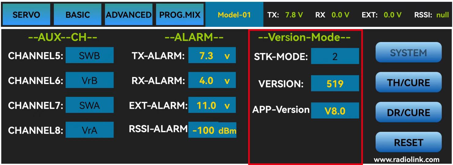
The interface of parameter setup APP on phone.
The interface of the parameter setup software on the computer.
3.4.4.4 RESET
This function is to restore the factory setting when necessary. When press this “RESET” button, T8FB will make three slow D sounds, meaning default setting is set.
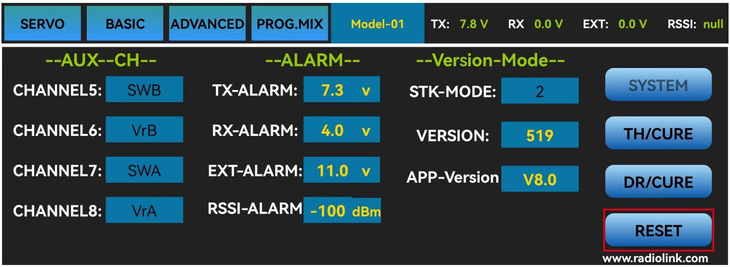
The interface of the parameter setup APP on the phone

The interface of the parameter setup software on the computer
Chapter 4 Firmware Upgrade
4.1 Firmware Version
The firmware version can be checked through mobile phone or computer, and you can judge whether it is necessary to upgrade the firmware according to the current T8FB version number.
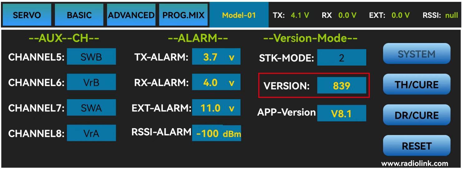
The firmware version on the parameter setup APP on the phone
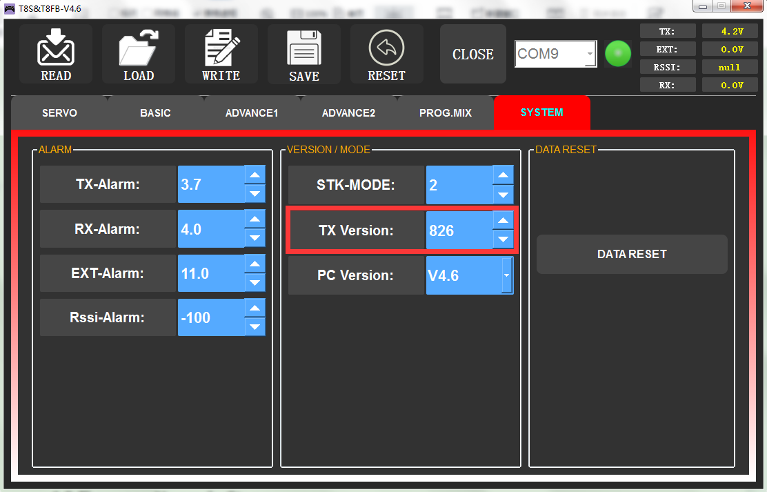
The firmware version on the parameter setup APP on the computer
4.2 Firmware Upgrade Steps
Please refer to the link https://www.radiolink.com/t8fb_bt_firmwares to download the latest firmware of T8FB and view the detailed steps on how to update it.
Tutorial video for T8FB how to upgrade firmware
Chapter 5 T8FB Joystick Calibration
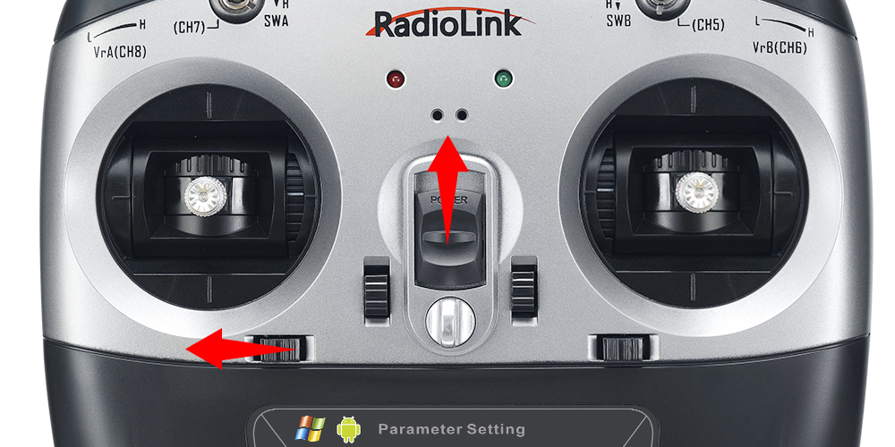
When the joystick of the T8FB is not in the center position, or there is large difference of the travel amount, the joysticks need to be calibrated. T8FB joystick calibration method is as follows:
1) When the transmitter is power-off, toggle both sticks at the central point. Press rudder trimmer left and turn on transmitter at the same time, red and green LED will start flashing and the T8FB is ready to be calibrated.
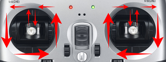
2) Range Calibration: Toggle both sticks (Ch1-4) to the highest point/maximum and the lowest point/minimum. Then back to the central point. (Refer to image below)
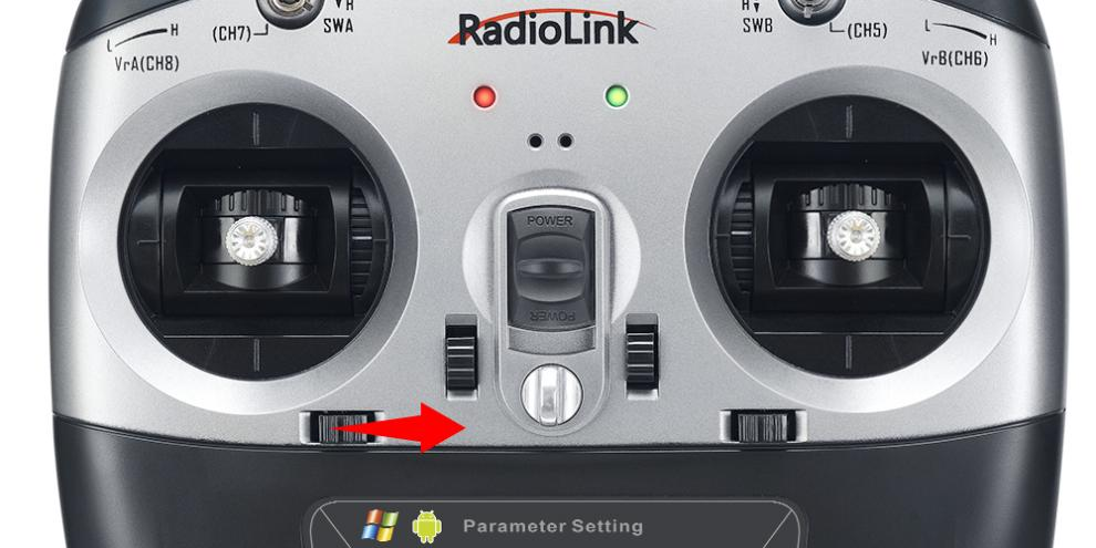
3) Central Point Calibration: When the joysticks are back to the central point, press rudder trimmer right, and then red and green LED always on means sticks calibration is done with success. Then turn off T8FB and repower it on.
Technical Support Here
If the above communication cannot solve your problem, you can also send emails to our technical support: after_service@radiolink.com.cn
Thank you again for choosing RadioLink product.