
Packing List
Pictures | Item | PNP | PNP FPV | RTF | RTF FPV |
| F121 box | 1 | 1 | ||
| Carrying/Shoulder Bag | 1 | 1 | ||
| F121 | 1 | 1 | 1 | 1 |
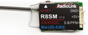
| R8SM Receiver | 1 | 1 | ||
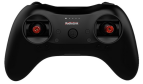
| T8S Transmitter | 1 | 1 | ||
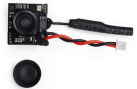
| FPV Camera | 1 | 1 | ||
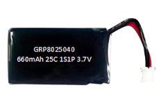
| 660mAh Li-Po Battery | 1 | 1 | 2 | 2 |
| GEMFAN Spare Propeller(4 for a set) | 2 | 2 | 2 | 2 |
| Propeller Guard | 4 | 4 | 4 | 4 |
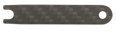
| Propeller Remove Tool | 1 | 1 | 1 | 1 |
| Hawkeye 4.3 FPV Monitor | 1 | |||
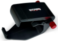
| TX and FPV Monitor Holder | 1 | |||
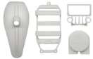
| Shell for DIY | 1 | 1 | ||
| Hook and Spring | 1 | 1 | ||
| Battery Charger | 1 | 1 | 1 | 1 |
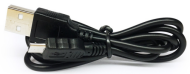
| USB Cable | 1 | 1 | ||
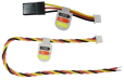
| RX and FC Connect Cable | 1 | 1 | ||
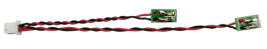
| Direction LED for night flight | 1 | 1 | 1 | 1 |
| Screwdriver | 1 | 1 | 1 | 1 |
| F121 User Manual | 1 | 1 | 1 | 1 |
| Hawkeye FPV Manual | 1 |


Note: For F121 RTF FPV, you can choose FPV monitor or FPV goggles according to your needs.
Chapter 1 Features of F121
As the mini racing drone that can fly at high speed at Altitude Hold Mode, F121 is very easy to master for drone freshman. The inertial navigation system technology blending Kalman filtering, gyro, accelerometer and barometer makes F121 possible to flight through narrow space with accuracy and hold altitude even it’s less than one-meter height to the surface or at high speed. With three flight modes Alt-Hold at low speed, Alt-Hold at high speed and Stabilize, beginners can flight stably at the first trial.
F121 is monitored by RadioLink mini racing drone flight controller F121, which is different from other flight controllers with PID needs to be set before use,will tune automatically. The software noise reduction technology not only enables a more pleasant flight but also makes the motors more responsive and more efficient than traditional 8520 coreless motors.It can be thrown and start to fly at any angle even under high-speed and remains stable even facing with sudden airflow fluctuations such as during takeoff, under braking, or after extended flying. Without compass locking, F121 always automatically modify angles during flight .
Chapter 2 Before Flight
2.1 Power Supply
Power for transmitter T8S: Make sure the transmitter is fully charged.
Power for F121: The voltage of 1S LiPo battery packed with F121 by default is not fully charged so the battery needs to be charged with the charger CM120 before flight.
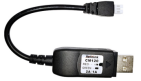
The LiPo battery charger CM120, specially designed for 1S LiPo battery, sharing the professional development and high precision of CB86PLUS, ensures safer charging and battery life span.
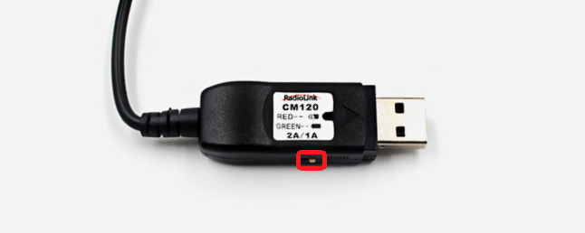
Charging current can be set as 1A or 2A by toggling the switch at the side of the charger.
The Red LED flashes slowly indicates the battery is under charging. The Green LED always on indicates the battery is fully charged. The Red and Green LED Flashing alternately indicates Fault prompt.
CM120 applies general USB connector, both computer and power bank for mobile phone can be used with CM120.
Note Voltage output of power supply should be NO higher than 5V.
2.2 Transmitter
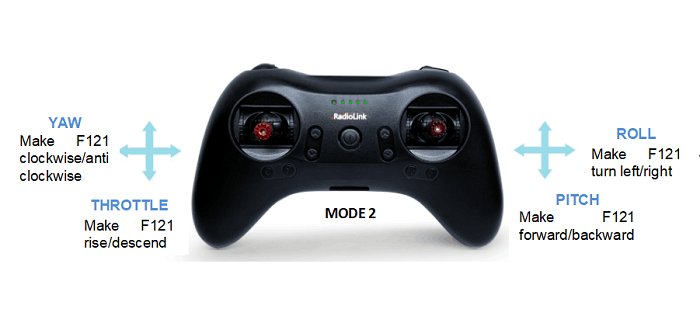
The two joysticks of T8S correspond to the four basic channels respectively . The below example takes RadioLink radio T8S Mode 2 (Throttle on the left stick) .
Left joystick
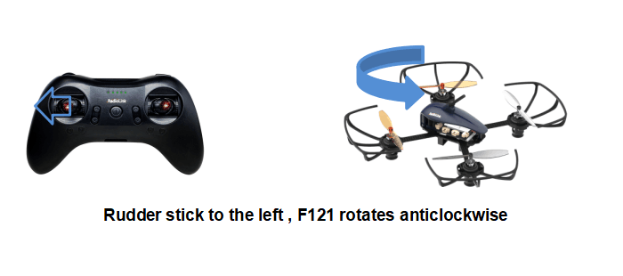
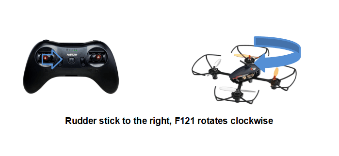
Make the F121 rise or descend by toggling the left stick(THROTTLE) vertically upward or downward and turn clockwise or anticlockwise by toggling the left stick(YAW) to the left or right.
Right joystick
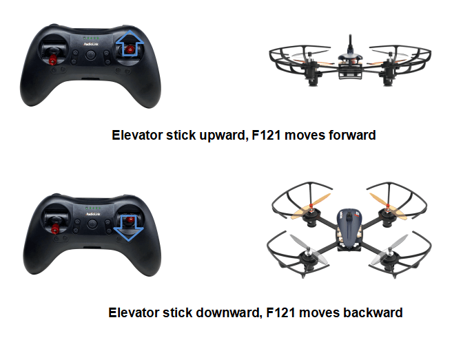
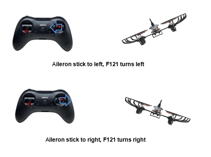
Make the F121 fly forward or backward by toggling the right stick(PITCH) vertically upward or downward and to left or right by toggling the right stick(ROLL) to the left or right.
Note If it’s the transmitter from other brands used with RadioLink F121, make sure that the receiver should be SBUS signal output supported. Once the receiver is installed on the mini drone, the phase of the throttle should be reversed while the other three channels normal and the CH5 should be set with a 3-way switch. Servo phases of transmitters from other brands should be set according to the actual situation.
2.3 F121
Assembled as building block makes the RC students exercise their DIY ability and free from lengthy mobile games.Learning knowledge of science and technology when assembling, setting parameters and flight.
2.4 Joysticks & Flight Movements
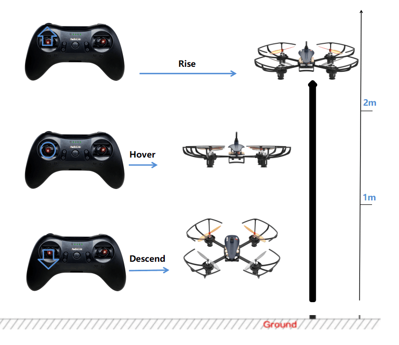
A. Throttle: Rise/ Descend/Hover
Toggle the throttle stick (on the left) vertically upward and F121 will rise and toggle the throttle vertically downward, then F121 descends.
If at Alt-Hold Mode, toggle the throttle stick vertically upward till the F121 rises to the preferred height, then toggle back to center position and release, the F121 will remain at this height.
Yaw: Clockwise/Anticlockwise
Toggle the yaw stick (on the left) to the left and F121 will turn anticlockwise and toggle the yaw stick to the right, then F121 turns clockwise.
Pitch: Forward/Backward
Toggle the pitch stick (on the right) vertically upward and F121 will fly forward and toggle the pitch stick vertically downward, then F121 flies backwards.
Roll: Right/Left
Toggle the roll stick (on the right) to the left and F121 will fly to the left side and toggle the roll stick to the right, then F121 will fly to the right side.
Chapter 3 Get Ready to Flight
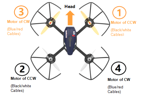
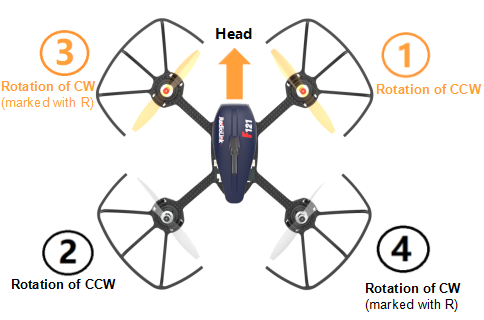
Motor Installation
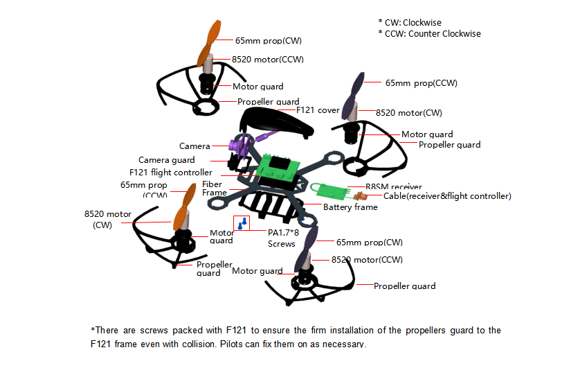
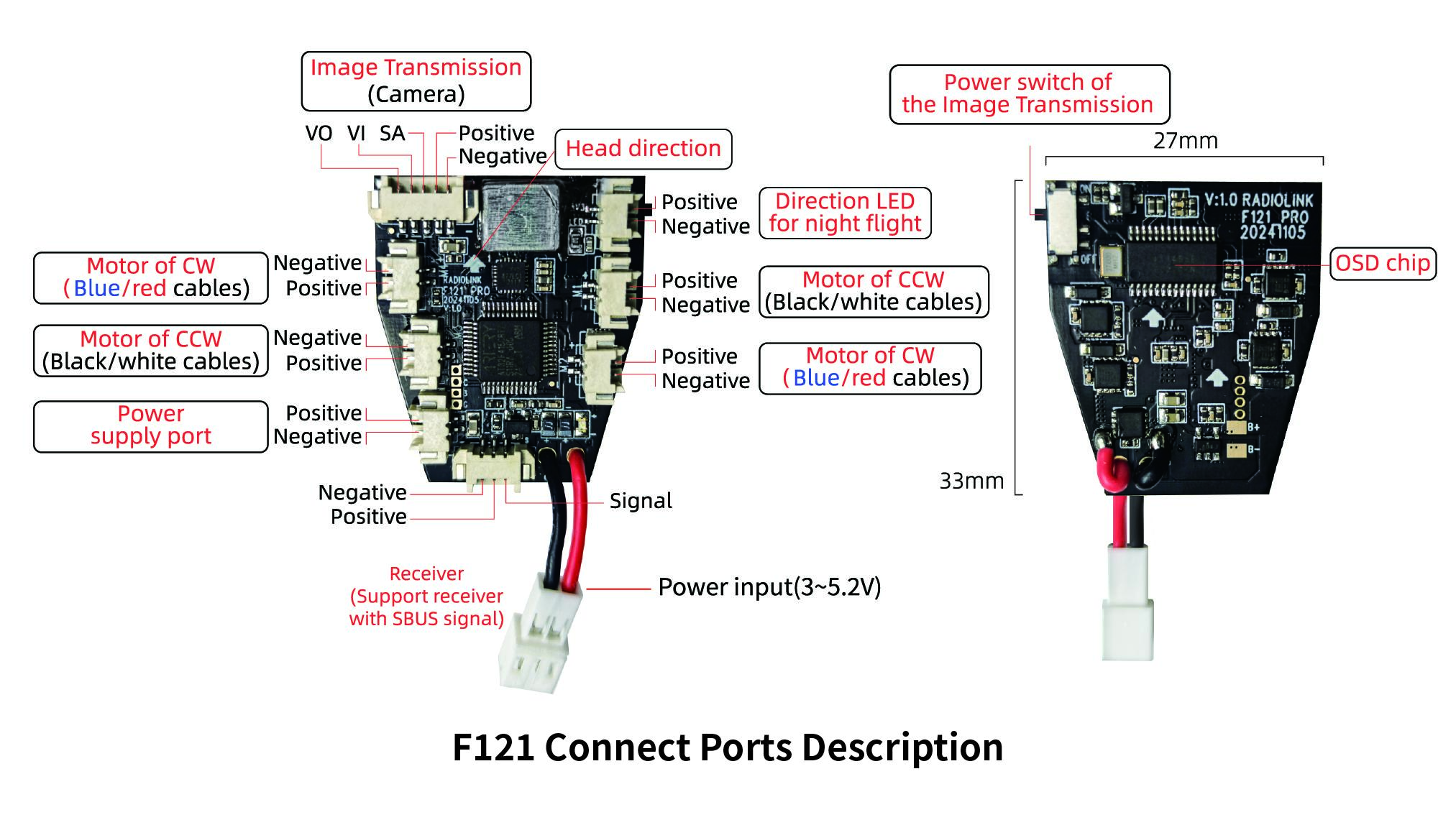
To make the aircraft fly, motors usually rotate clockwise(CW)/counterclockwise(CCW) with the propellers. The rotation direction of F121 motors can be identified by the cable colors. That is, red/blue means motor of clockwise(CW) while black/white means that of counterclockwise(CCW). It is very important to make sure about the rotation direction as below when installing motors. Otherwise, the drone would fail to take off.
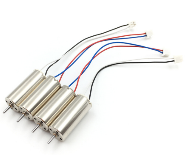
* Motors installation can be skipped as the whole F121 is already assembled by factory default. If any of the motors is worn out and needs to be replaced, it’s essential to identify the correct motor rotation.
3.2 Propeller/Propeller Guard Installation
F121 is installed WITHOUT propeller guards by factory default because of the package consideration. To ensure a safety flight, it’s strongly advised to check if the guards are well installed .
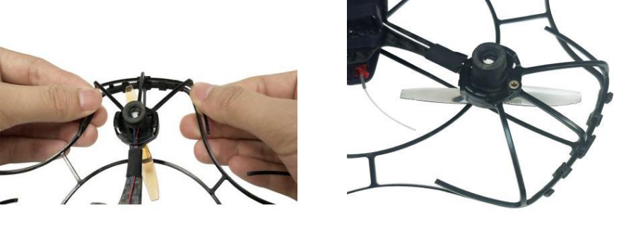
Half-covered propeller guard installation
Find the two notches respectively on the motor guar dand propeller guard as image as below.
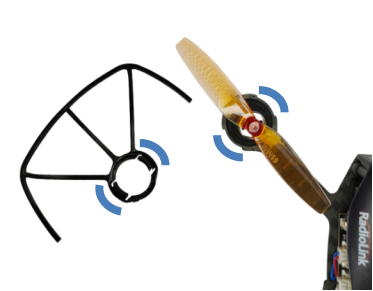
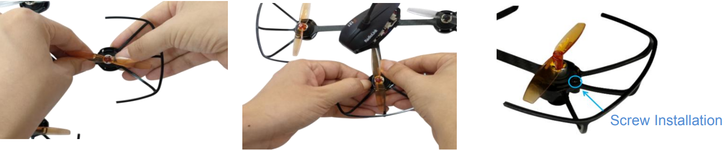
Put on the propeller guard from the bottom and adjust the position of the notches correspondingly.
Stabilize the frame with left hand and buckle the notch of one side with right hand. Then buckle the notch of the other side with left hand. A “DA” sound will be heard if the installation is done with success.
Extra 4 screws are in the package and pilot can installed on the propeller guard as prefer.
Full-covered propeller guard installation
If your F121 comes with full-covered propeller guards (Please refer to the sales interface), please install the full-covered propeller guards after the installation of the half-covered propeller guards. Align the tab of the full-covered propeller guards and half-covered propeller guards. Match and press them from the left to the right until all tabs correspond to notches. Then follow this step to install all the propeller guards.
Note After the installation of the four propeller guards, double confirm if they are leaning or slightly shake F121 to see if they drop. If they are crooked or drop, repeat the above steps to ensure the well installation.
Propellers installation can be skipped as the whole F121 is already assembled by factory default. If the default propellers get worn and needs to be replaced after a period of flight, it is important to well identify the rotation direction of propellers. If installed incorrectly, F121 can’t take off even the throttle is pushed to max.
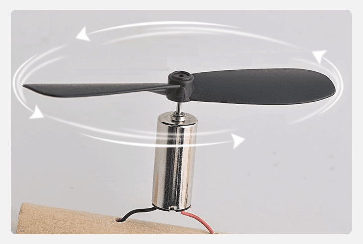
In order to identify the propellers rotation, take a propeller and observe there’s a radian at both sides of the small cylinder in the middle. The higher part (also called windward side) of the right propeller is at the front and the rotating motor will make propeller rotate counterclockwise(CCW). On the contrary, that is clockwise(CW) rotation. For the 65mm GEMFAN propellers used on F121, there are two marked with a letter R, meaning they should be installed on the motors of clockwise.
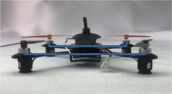
When the installation is done, make sure the four motors are vertical to the aircraft frame. Adjust them to vertical positions if necessary, otherwise F121 may not flight successfully.
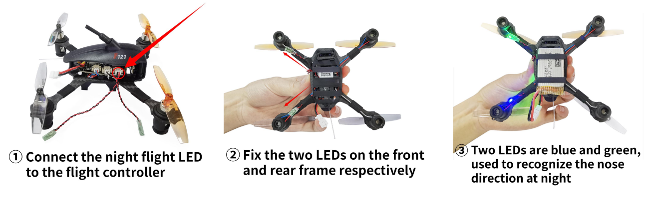
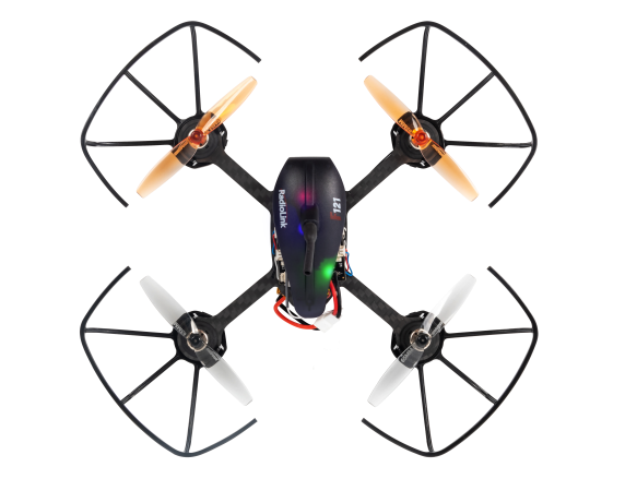
3.3 Guide on Direction LED for Night Flight
F121 comes with direction LED in green and blue for night flight. When flying at night or in a dark room, it can help to indicate the aircraft nose. Please follow the below steps to install and use it.
3.4 Power On F121
Before powering on F121, fully charge the 1S LiPo battery first. Plug the PH2.0 end of the battery into the F121, then insert the battery into the battery frame under at the bottom of F121.
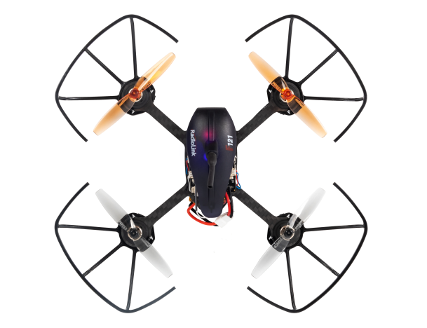
Orange propellers indicates the head of F121 by default. make sure they point to the same direction as the pilot when powering on and be ready to fly, to ensure safety.
The green LED of F121 will begin flashing when powered on. When it’s off, it means F121 finishes calibration.
Note Head direction is determinate. If F121 is calibrated with the direction different from the default, it will turn back to the default direction automatically when starts flying, That’s what we called Head Front Forward Point Without Compass. When the flight controller incorrectly recognizes the nose direction, you can re-power the aircraft, or make the flight controller re-identify the nose direction by re-calibrating the aircraft.
3.5 Flight Note
If it’s the first time of flying drone, flight mode of Altitude Mode-Low Speed is strongly advised to set. At the altitude mode, when toggle the throttle upward till the drone reaches a certain height and release, F121 will remain at this height. It’s simpler because pilots only need to toggle the other joystick to make the F121 move forward/backward or turn left/right. If it’s the Stabilize Mode chosen, try to toggle the joysticks slightly to correct the flight and avoid the drone having sudden moves.
If F121 drops by hitting something, toggle throttle stick to the bottom position immediately to stop motor rotation.
Make sure the signal output of receiver is SBUS to ensure normal operation of F121. For RadioLink receivers(R8SM/R6DSM) installed on F121, the led indicator is blue/purple when it’s SBUS working mode.
3.6 Setup Compatible Transmitters
By factory default, F121 standalone version doesn’t have receiver installed while RTF version is packed with the transmitter T8S and receiver R8SM combo. Receiver R8SM is also compatible with RadioLink T8FB/T16D/T12D transmitter. If it’s RadioLink transmitter AT10/AT10II/AT9/AT9S/AT9S Pro used with F121, compatible receiver should be R6DSM.
When using transmitters and receivers from other brands, please note:
1. Check the minimum working voltage of the receiver.
The minimum working voltage of many mini receivers on the market can only reach 3.7V, while aircrafts with coreless motors are usually powered by 1S 4.2V lithium batteries, and the voltage of the aircraft can easily drop below 3.7V during high-speed flight. Then the receiver will lose control due to insufficient power supply, and the aircraft will crash. So if you use transmitters and receivers from other brands, please pay attention to the minimum working voltage of the receiver. The minimum working voltage of RadioLink R8SM, R8FM, R6DSM mini receivers and F121 flight controllers can work well even when it reaches 2.3V.
2. Please make sure that the receiver you are using supports SBUS signal.
T8FB/T8S
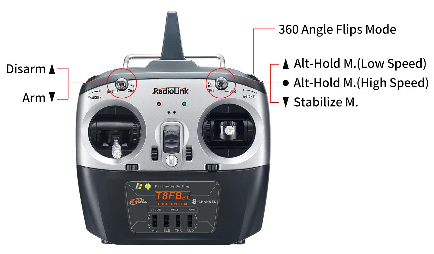
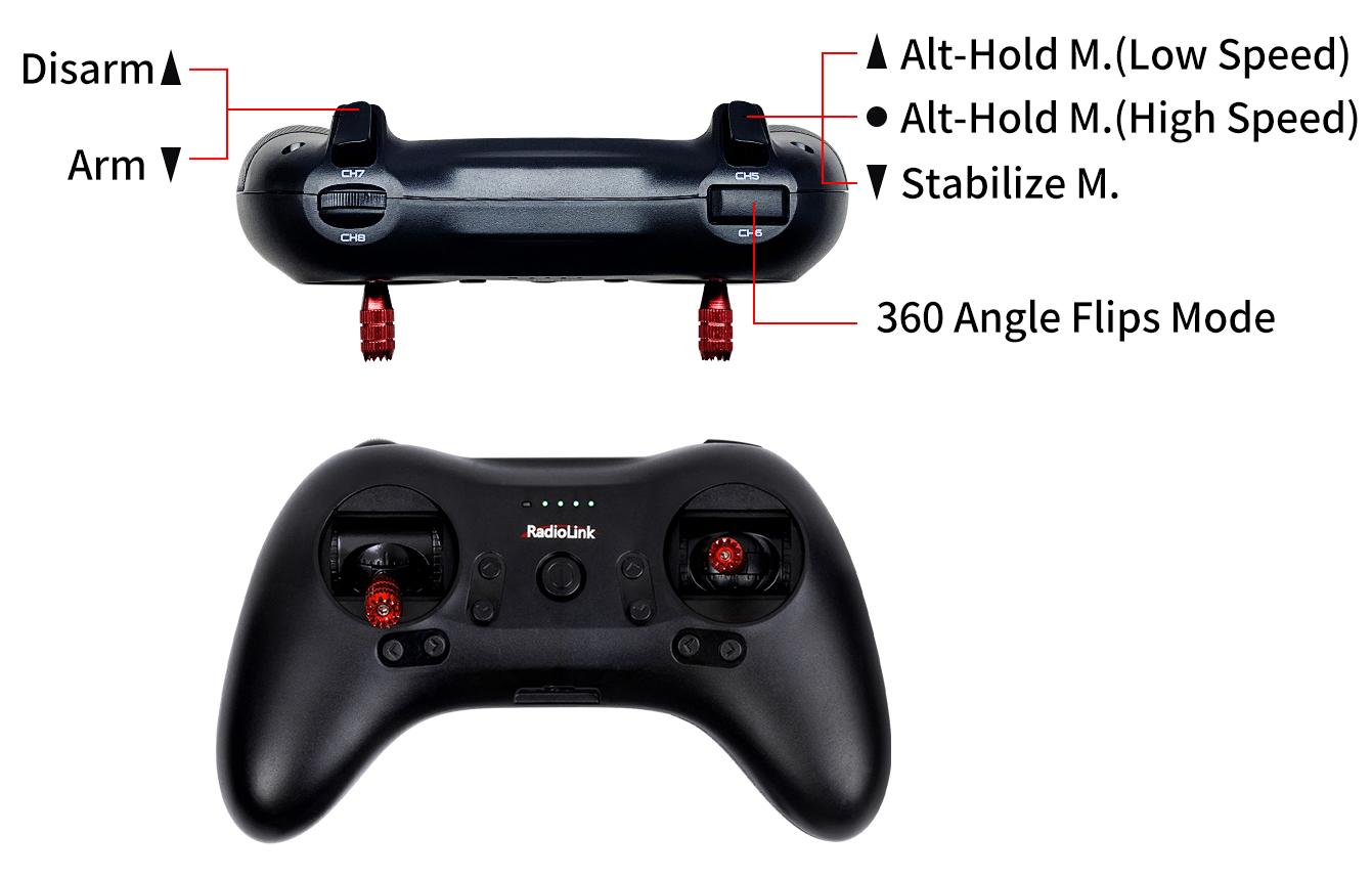
RadioLink 8-channel transmitter are well set by factory default with the flight modes. To control F121, binding is the only thing needs to be done.
There are three flight modes for F121 including Altitude Mode- Low Speed, Altitude Mode- High Speed and Stabilize Mode. The flight modes can be switched by pressing the three-way switch on T8FB- SWB or T8S- CH5, and T8FB- SWA or T8S- CH7 is used to arm/disarm the aircraft, as shown below:
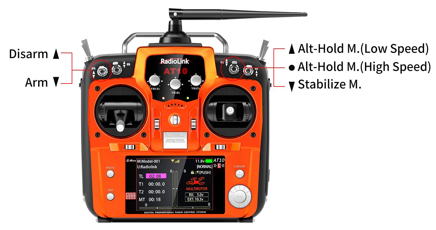
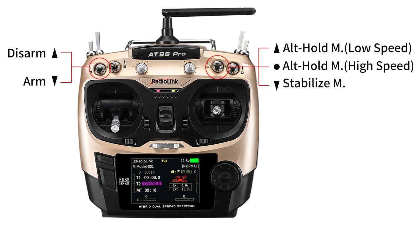
T16D/T12D/AT9S Pro/AT9S/AT9/AT10II/AT10
(1) Enter BASIC MENU, select MODEL TYPE (For T16D/T12D: Enter Advanced Settings--TYPE SELECT) and choose MULTIROTOR.
(2) Return to BASIC MENU, select REVERSE (For T16D/T12D: Enter General Settings--REVERSE) and set CH3 Throttle as REV.
(3) Return to BASIC MENU, select AUX-CH (For T16D/T12D: Enter General Settings--AUX-CH) and set CH7 control switch as a 2 position switch such as SwA.
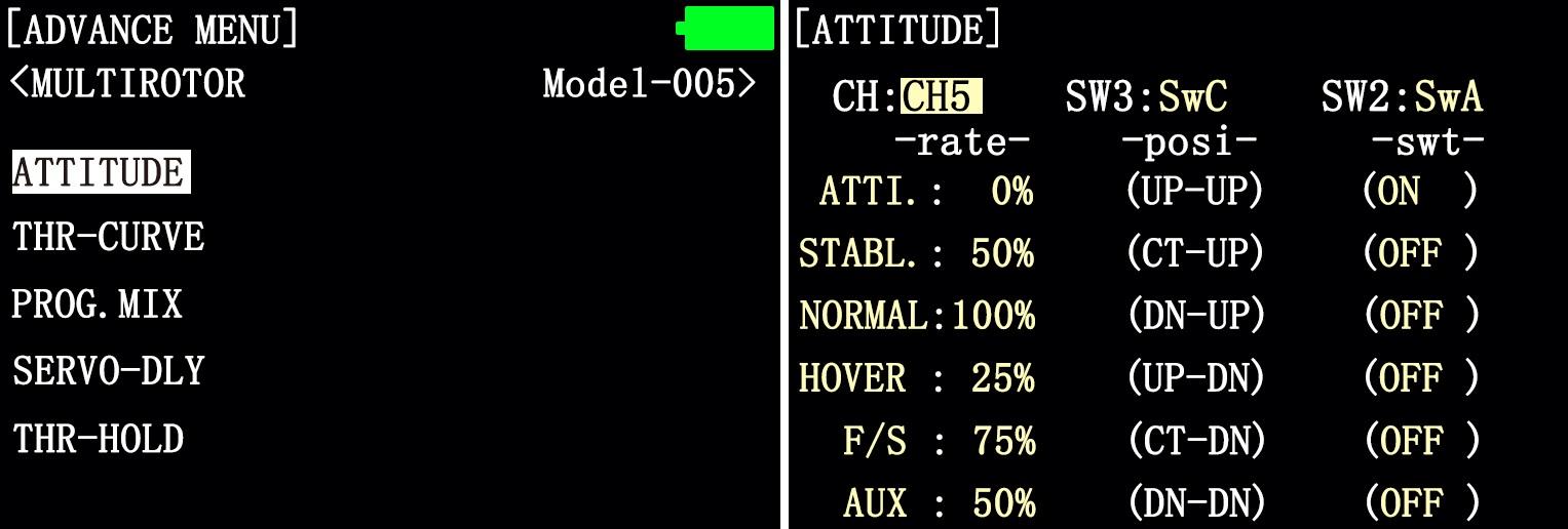
(4) Enter ADVANCE MENU, select ATTITUDE (For T16D/T12D: Enter Advanced Settings--FLIGHT MODE) and set the CHANNEL as CH5, SW3 as SWC with up position as Alt-Hold Mode(Low Speed), middle position as Alt-Hold Mode(HIgh Speed) and low position as Stabilize Mode.
* For more setting instructions of different RadioLink transmitters, please visit www.radiolink.com to download the corresponding detailed e-manual.
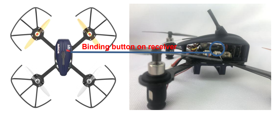
3.7 Binding
If it’s the RTF version( whole pack including T8S+F121+bag) purchased, there’s no need to bind because the binding is complete with receiver R8SM installed by factory default. However, if F121 PNP version is purchased, please bind them. Here are the binding steps:
Place the transmitter and receiver(installed on F121) close to each other within 50 centimeters.
Power on the transmitter and F121.
There is a black binding button(ID SET) on the side of the receiver, press it for more than 1 second. When the LED starts flashing, meaning binding process has started.
The binding is complete when the LED is always on.
Make sure F121 is armed (Details in next section). Gently push the throttle of transmitter to see if motors move. If doesn’t, retry binding again.
Note
F121 currently supports SBUS signal output only, always make sure the LED of R8SM/R6DSM is blue/purple, meaning SBUS signals output. If the LED is red, press the binding button twice in 1 second and release to change it to purple/blue.
When using AT9S Pro/AT9S/AT10/AT10II transmitter with R6DSM receiver, please enter BASICE MENU-- SYSTEM and modify CH-SELECT as 10CH on the transmitter. Otherwise, F121 won’t be able to be armed.
When using T16D/T12D transmitter with R8SM receiver, please enter Receiver setting--RF SETTINGS, and select FHSS V1 protocol on T16D/T12D. Otherwise, the receiver cannot be bound to T16D/T12D.
3.8 Arm and Disarm F121
A. How to arm
When the throttle stick is at the lowest position, push up the CH7 switch (the 3-way switch on the left of T8S), the green LED of F121 is on means arm successful. When the transmitter is T8FB, push the throttle stick to the lowest position and then put down the CH7 switch (the 2-way switch on the left) to arm. If you use the other transmitter except the T8S or T8FB to control the F121, set a 2-way switch to control the CH7, and when the throttle stick is at the lowest position and the switch at the low position, the green LED of F121 is on means arm successful. For security reasons, F121 will be disarmed automatically if there is not any operation of the throttle for 5 seconds. So arm F121 again when the flight is ready.
B. How to disarm
When the flight is finished, always make sure F121 is disarmed when get close and try touching it to avoid unexpected harm. Always be sure about turning off F121 before T8S.
Press down the CH7 switch (the 3-way switch on the left of T8S), the green LED of F121 is off means disarm successful. When the transmitter is T8FB, put up the CH7 switch (the 2-way switch on the left) to disarm. If you use the other transmitter except the T8S or T8FB to control the F121, set a 2-way switch to control the CH7, and when the switch at the high position, the green LED of F121 is off means disarm successful.
Chapter 4 Flight at Different Flight Modes
It’s strongly advised for beginners to start from Altitude Hold Mode (Low-speed) to Altitude Hold Mode (High-speed) then to Stabilize Mode.
It’s better to keep the direction of F121 head same as pilot in order to easily judge the flight direction. Otherwise, F121 may flight towards pilot and get him/her hurt. If the aircraft head is changed unexpectedly and different from pilot’s direction, pull the throttle stick to the lowest position to land F121.
4.1 Altitude Hold Mode (Low-speed) and Altitude Hold Mode (High-speed)
4.1.1 Rise/Descend
Press the CH5 switch of T8S backward, which makes F121 fly at Altitude Hold Mode (Low-speed). Make sure the orange propellers at front when powering F121 on. Then arm F121 and push the throttle joystick vertically upward higher than center position, then the F121 will rise while if push it vertically downward, then the F121 will descend.
4.1.2 Hover
Push the throttle joystick vertically upward till the F121 rises to a height as wish, then toggle it back to center position and release , the F121 will hover at this height.
4.1.3 Forward/Backward/Right/Left
At Altitude Mode, F121 is able to fly forward/backwards or towards to right/left by toggling the right stick at the certain height .
For beginners, make sure to push the stick gently because being a racing drone, F121 is very responsive. It’s advised to release the stick as soon as toggle to one direction so that F121 will back to level automatically. Otherwise, F121 will keep flying to the toggled direction with accelerated speed.
4.1.4 Clockwise/Anticlockwise Rotation
When get familiar with the above flights, try flight clockwise/anticlockwise because the yaw practice is more difficult to judge the flight direction. Clearly knowing the direction will quickly help master drone flight. Try imagine sitting on the drone could be a better way to practice.
Toggle the rudder joystick to the left and F121 will flight anticlockwise while if to the right, then the F121 will flight clockwise.
4.2 Stabilize Mode
Press the CH5 switch of T8S backward and it keeps F121 work in Stabilize Mode.
When at Stabilize Mode, F121 will flight faster than when at Altitude Mode. Toggle joysticks as gentle as possible to avoid drastic movements, which may possibly hurt the pilot. Make sure that the battery is fully charged before enjoying the flight.
Once get familiar with the low speed and high speed at the Altitude Mode, beginners can practice how to rise/descend,hover, pitch forward/backward, move to left/right and rotate to clockwise/anticlockwise at the Stabilize Mode, which is more challenging.
4.3 Switch for 360 Angle Flips Mode
F121 add a mode named Switch for 360 Angle Flips Mode except Altitude Hold Mode, and Stabilize Mode. The setting steps as below:
When the transmitter is T8S, press the CH6 switch twice continuous and then push the aileron or elevator stick. If push the aileron stick to the left, the F121 will roll 360 degrees to left. If push the aileron stick to the right, the F121 will roll 360 degrees to right. If push the elevator stick upward, the F121 will roll 360 degrees forward. If push the elevator stick downward, the F121 will roll 360 degrees backward.
When you ready to controlling your F121 roll 360 degrees backward, you must fly your F121 far away from yourself first to ensure safety.
When the transmitter is T8FB, the 360 Angle Flips Mode switch is VrB, the operating steps are same as T8S.
Attention: The interval time for push the aileron or elevator stick do not more than 5 second when you press the 360 Angle Flips Mode Switch. You have pressed the switch again if the time is more than 5 second.
Note When the green LED on F121 starts flashing during flight, it means the voltage of F121 is lower than 3.8V as this value is default for 1S battery. It’s advised to stop flying to avoid battery over discharging.
Chapter 5 Image Transmission of F121
The image transmission device of F121is 5.8G 25mW all-channel camera integrated image transmission. If it’s the image transmission version purchased, the binding between F121 and the FPV screen has been done by factory default. Pilots only need to power both on before flight. If it’s the standalone version of F121, an FPV screen or a goggles with integrated 5.8G image transmission receiver is needed and setup by following its instructions.
The default transmission power is 25MW. Available power among 25MW,100MW and 200MW can be changed by pressing the button on the camera. More instructions about setting the power, please visit www.radiolink.com for detailed manual.
Note As device of image transmission includes transmit and receive, the distance could be influenced by the gain of transmit and receive.
5.1 Little Pilot (SCHOOL) All-in-one 4.3 inch FPV Monitor
5.1.1 Buttons and Functions
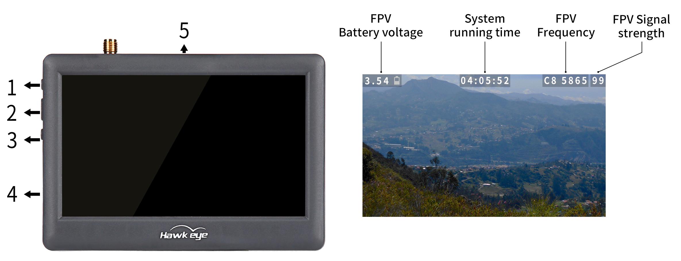
Button Name | Function |
1. Adjustment button(+) | Short press to select desired frequency from 6 groups A-B-C-D-R-F |
2. Power/Menu button | Long press to turn-on/off |
3. Adjustment button(-) | Short press to select desired frequency from groups 1 - 2 - 3 - 4 - 5 - 6 - 7 - 8 |
4. Micro USB Charge port | Charging |
5. Reset | Reset |
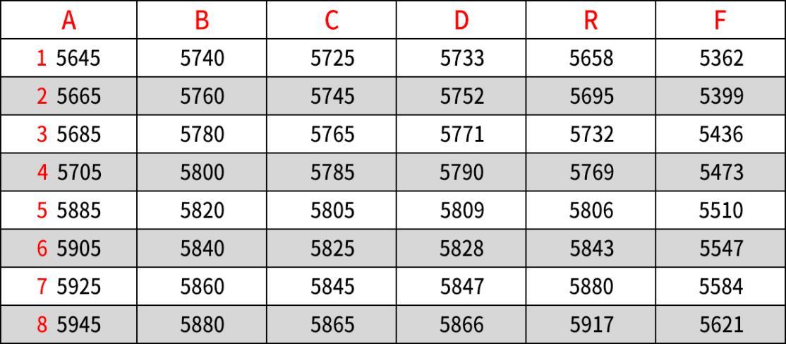
5.1.2 Little Pilot Monitor Frequency Group Selection
5.1.3 Bind Little Pilot Monitor to F121
1. Automatic binding (Recommended):
Power on F121, and then long press button(+) in Little Pilot FPV to start auto search. After searching, the FPV screen with the strongest signal will be automatically displayed.
2. Manual binding:
① Check the frequency of F121 according to the method in Chapter Chapter 5.3.2 Customize the power/band/frequency
② Match frequency of F121 to the frequency table of Little Pilot FPV. Short press button(+) to adjust to the corresponding frequency band, and short press button(-)to adjust to the corresponding frequency point
For example, the frequency of F121 is B5, 5809, according to the method in Chapter 5.3.2 Customize the power/band/frequency. 5809 corresponds to D5 in frequency table of Little Pilot FPV Monitor. After the FPV monitor is turned on, adjust the band/frequency at the top of the screen to D5 by short pressing the button(+) and button(-) to complete the binding.
5.2 ZENCHANSI 3-inch FPV Goggles
5.2.1 Buttons and Connectors
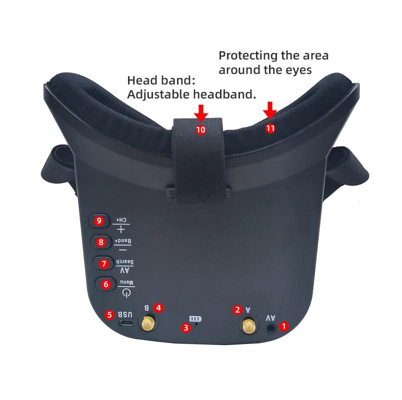
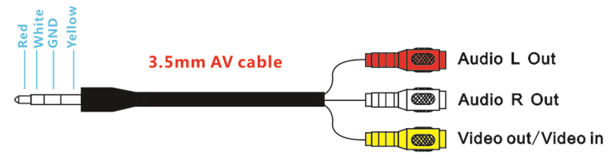
① AV Jack: Output Audio signal in RF receiving mode; Enter the video signal in RF receiving mode.
② A: Antenna port A (RP-SMA Male)
③ EB: Antenna port B (RP-SMA Male)
④ Charging indicator: When it is charging, the red light is on; When it is full, the light is off.
⑤ Micro-USB charging port: Supports 5V/1.5A.
⑥ Power/Menu
Power: Short press into Power ON. Then short press into Menu. Long press for Power OFF.
Menu: Can be adjusted the display parameters.
⑦ AV/Search:
AV: Long press into AV mode. External video signal input should be CVBS, NTSC or PAL.
Search: Short press for Auto-Searching.
⑧-/Band+: Short press the "menu" button to enter the screen parameter setting and select the corresponding parameter. Press "-" to reduce the parameter value.
Band+: Short press for Band+ (Change bands A-B-C-D-E-R circularly).
⑨ +/CH+:
+: Short press the "menu" button to enter the screen parameter setting and select the corresponding parameter. Press "+" to increase the parameter value.
CH+: Short press for Channel+ (Change channels 1-2-3-4-5-6-7-8 circularly).
☆ Menu Display: BRIGHTNESS, CONTRAST, SATURATION and RESET.
5.2.2 AV Cable Introduction
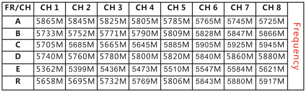
5.2.3 ZENCHANSI FPV Goggles Frequency Table
5.2.4 Bind ZENCHANSI FPV Goggles to F121
1. Automatic binding (Recommended):
Power on F121, and then short press Search button in ZENCHANSI 3-inch FPV Goggles to start auto search. The successful display of the image transmission means that the binding is successful.
2. Manual binding:
①Check the frequency of F121 according to the method in Chapter 5.3.2 Customize the power/band/frequency
② Match frequency of F121 to the frequency table of ZENCHANSI FPV Goggles. Short press Band+ button to adjust to the corresponding frequency band, and short press CH+ button to adjust to the corresponding frequency channel.
For example, the frequency of F121 is F5, 5820, according to the method in Chapter 5.3.2 Customize the power/band/frequency. 5820 corresponds to D5 in frequency table of ZENCHANSI FPV Goggles. After the FPV Goggles is turned on, adjust the frequency at the top of the screen to D5 by short pressing the Band+ and CH+ button to complete the binding.
5.3 Image Transmission of F121
5.3.1 Display of the image transmission
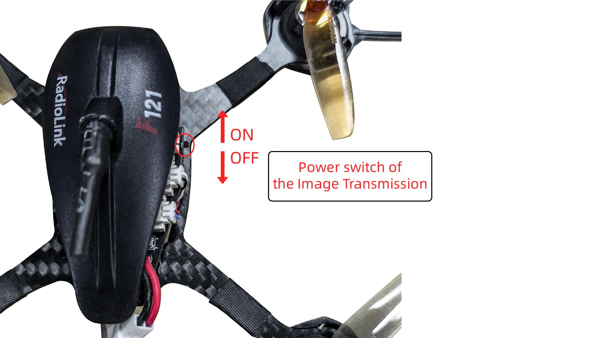
Push the power switch of the image transmission on the right side of F121 forward to power it on (As shown below). The red and blue LED lights are always on. Wait for 3 seconds for the initialization.
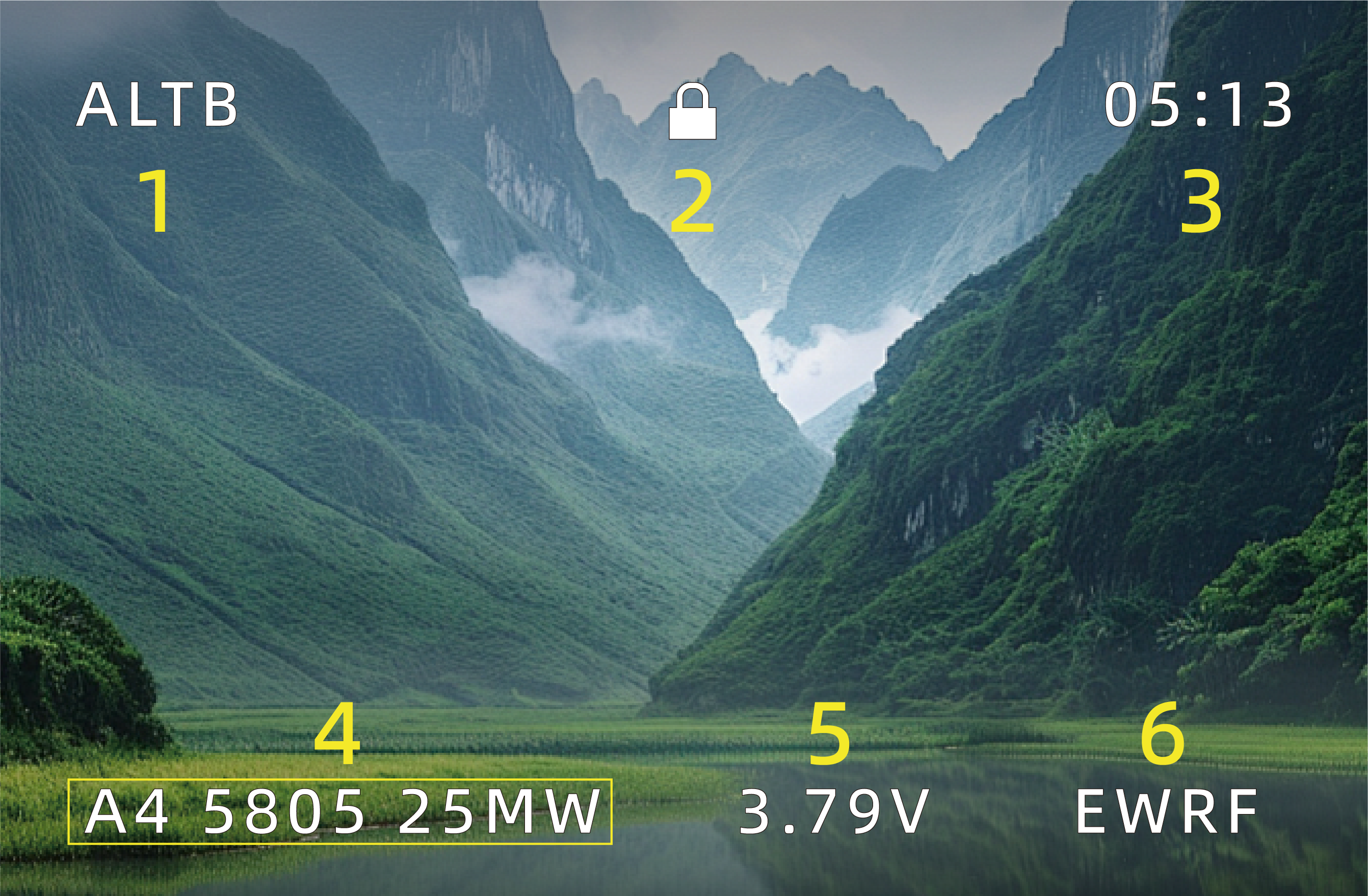
Here is the display of the image transmission after it is powered on:
No. | Meaning |
1 | STAB: Stabilize mode |
2 | When the lock icon |
3 | Power-on time of F121 |
4 | The frequency and power of F121 image transmission |
5 | When the battery voltage is lower than 3.2V, the voltage value will flash quickly. |
6 | The manufacturer of the image transmission |
 is displayed, F121 is disarmed and the propellers will not rotate; When the aircraft is armed, the unlock icon
  will be displayed and it will remain for 1 second before disappearing.
5.3.2 Customize the power/band/frequency
If you want to customize the power/band/frequency of the image transmission of F121, please follow the below steps:
After the receiver is bound to the transmitter, power on the transmitter and F121. Push the power switch of the image transmission on the right side of F121 to power it on (The red and blue LED lights are always on). Make sure F121 is disarmed.
Note: If F121 is armed, it cannot enter the image transmission configuration mode.
Enter the image transmission configuration mode.
Take the stick mode 2 (throttle on the left) as an example:
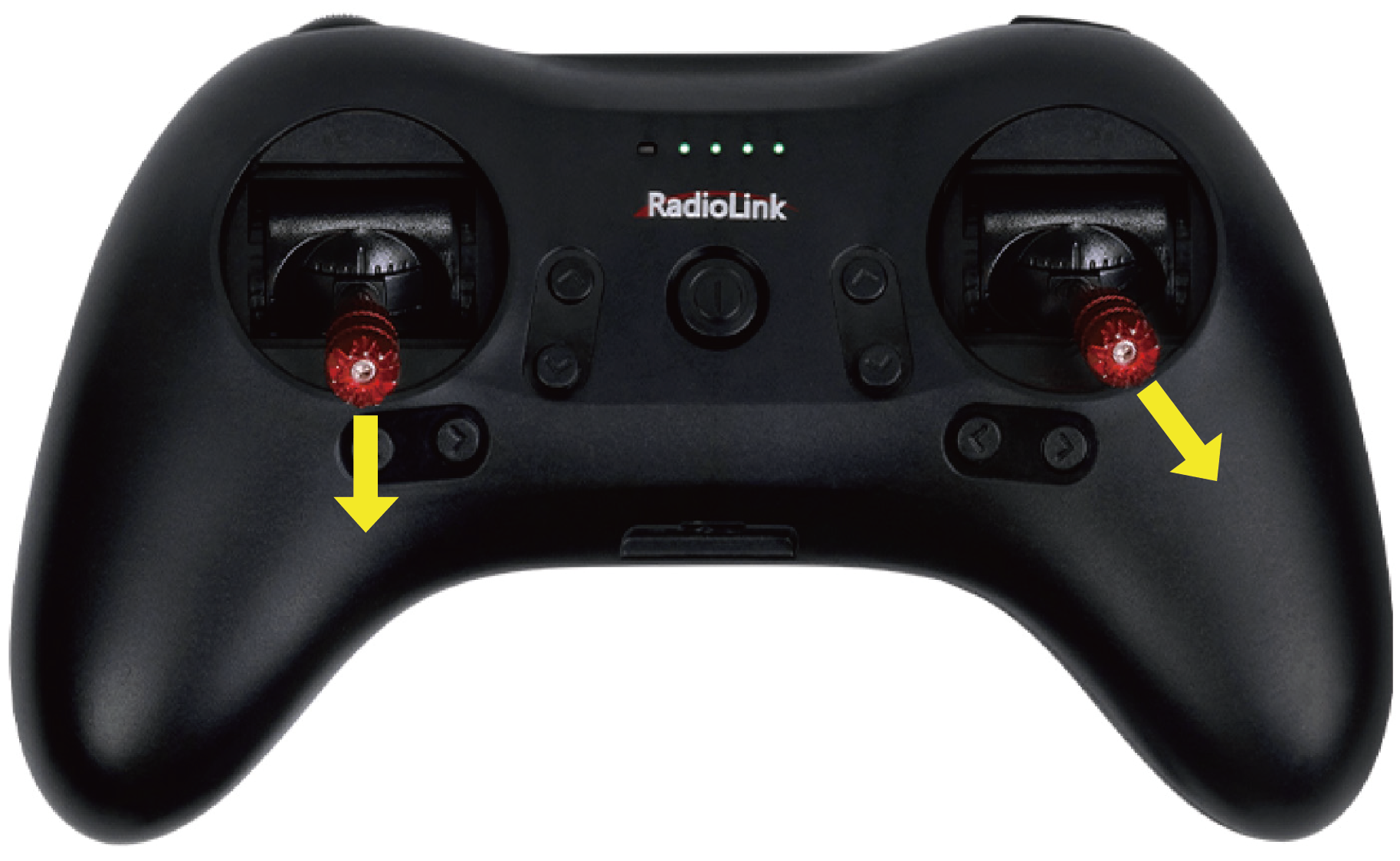
(1) Push the left stick to the lowest position;
(2) Push the right stick to the lower right corner;
(3) Keep the above actions for more than 2 seconds to enter the image transmission configuration mode.
Note: The stick position to enter the image transmission configuration mode is the same for mode 1 and mode 2.
Take mode 2 as an example
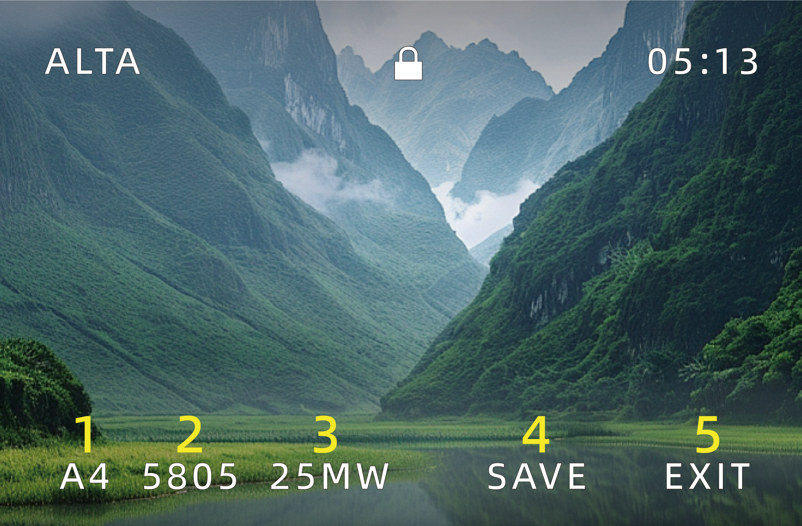
After entering the image transmission configuration mode, the frequency band will flash on the interface, and the words SAVE and EXIT will appear, as shown below:
No. | Meaning |
1 | The frequency band of F121 image transmission |
2 | The frequency of F121 image transmission |
3 | The power of F121 image transmission, including 25mW, 100mW, and 200mW |
4 | Save the modification |
5 | Exit the modification |
Switch the setting.
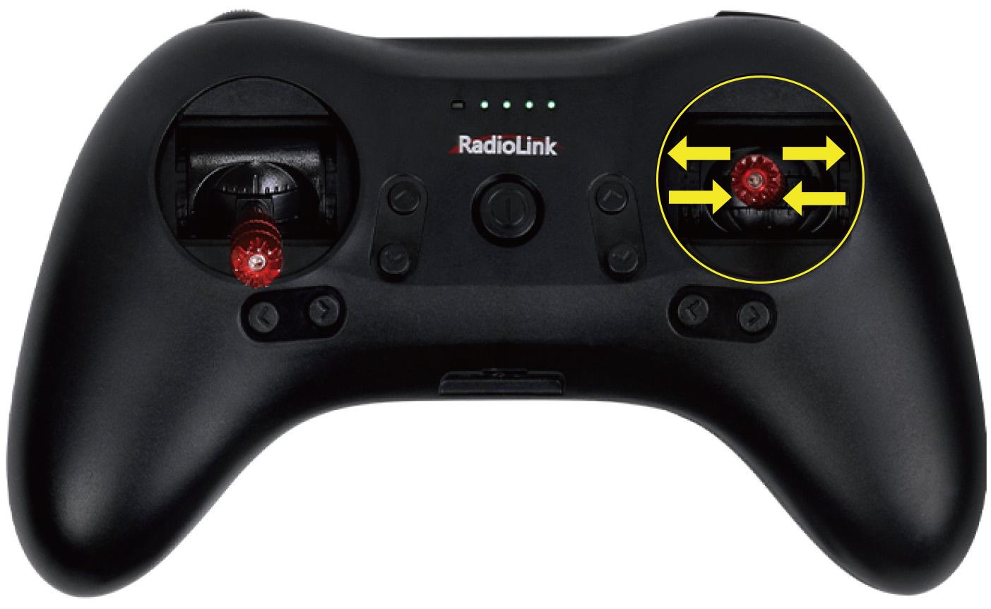
After entering the image transmission configuration mode, you can use the stick of CH1 (roll) to locate the specific setting such as frequency band or power.
Take mode 2 as an example. Move the right stick to the far right (or far left), and then return to the center (as shown below), and specific setting on the screen will flash, indicating that the current setting is selected.
Take mode 2 as an example
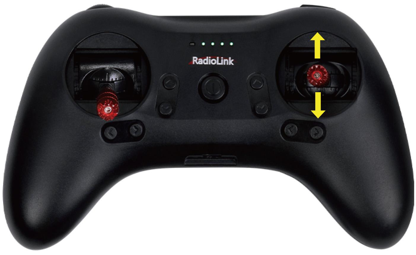
Adjust the value of the current setting.
When the current setting is selected, you can use the stick of CH2 (pitch) to modify it.
Take mode 2 as an example. Move the right stick up (or down) to the maximum, and then return to the center (as shown below), the value of the current setting will change.

Take mode 2 as an example
After the modification, move the right stick to select SAVE/EXIT. Then move the right stick (For mode 1, please move the left stick) up (or down) to the maximum and hold it for more than 1 second (as shown below) to exit the image transmission configuration
Note: EXIT means the current modification is not saved.
Take mode 2 as an example
Table of Band/Frequency
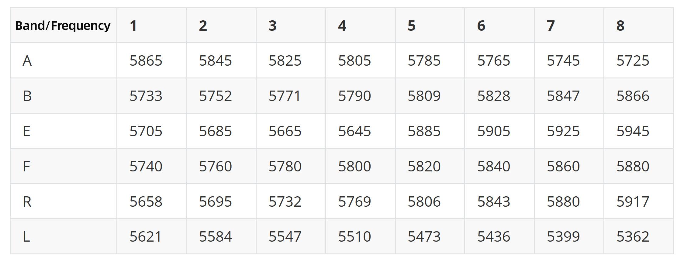
Note
When installing the image transmission camera, make sure the heat radiation is considered. Otherwise, the transmission power will decrease even turn off as the protection of over heating is activated.
It is normal that the camera will get heated during usage. DO NOT touch it directly with hands in case of getting burnt.
If the transmission antenna is broken or not well welded, the transmission distance will be impacted. Replace the antenna as soon as possible.
The detailed instructions of setting FPV screen and Goggles, please refer to its corresponding manual.
If there is interference during the usage, try switching the camera channel first, then search for a new channel on FPV screen or Goggles.
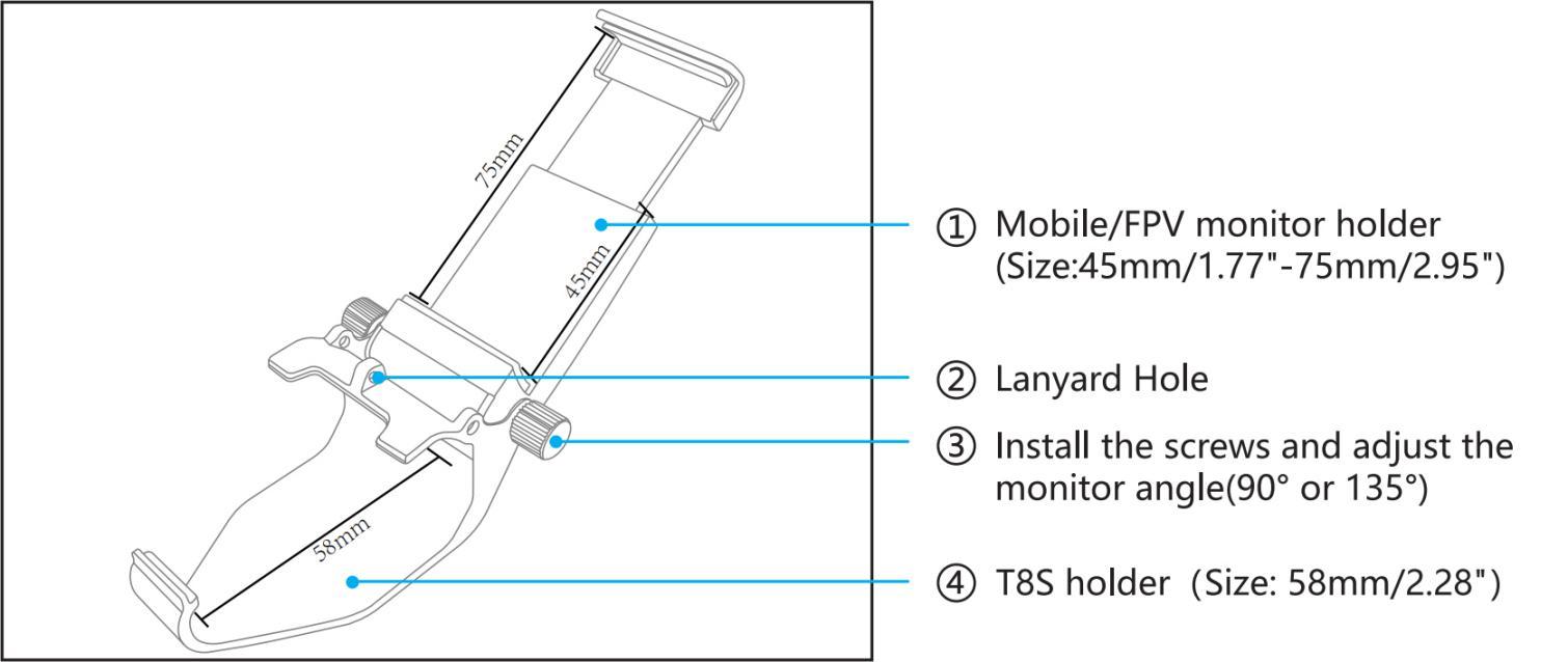
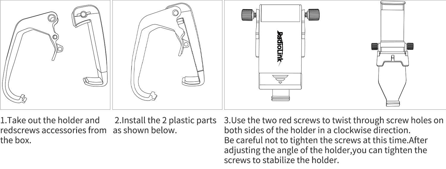
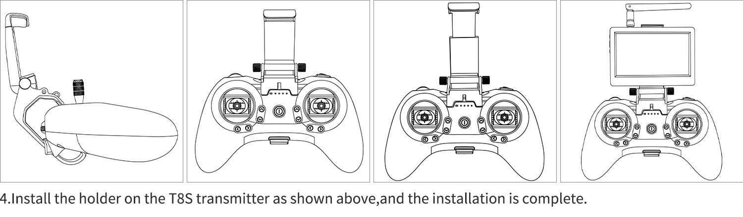
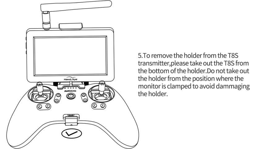
5.4 T8S Mobile/FPV Monitor Holder Instruction
Chapter 6 Specifications
6.1 F121 Specifications
Name: F121(Altitude Hold Micro Racing Drone)
Weight: 47.5g(Drone only)
Drone Size: 121*55mm(with antenna; 41mm without antenna)
Package Size: 170X210x113mm(RTF bag);210x163x67mm(Standalone box)
Transmitter Frequency: 2.4G
Image Transmission Frequency: 5.8G
Material: Carbon Fiber(Frame), Plastic(Cover, Bases for Image transmission/battery, Prop guard)
Motor: 8520 coreless with software to reduce noise
Propeller: GEMFAN propellers with diameter of 65mm
Transmitter: RadioLink 8-channel handle transmitter T8S
Receiver: RadioLink 8-channel mini receiver R8SM
Flight Controller: RadioLink flight controller F121
Battery: FULLYMAX 3.7V 660mA 25C LiPo Battery
Charger: USB Charger (1A/2A)
Flight Time: 10 minutes, suitable for Indoor and outdoor
Low Voltage Alarm: Green led flashes quickly when lower than 3.8V
Control Distance: 2KM in the air(Maximum range is tested in an unobstructed area free of interference)
6.2 Image Transmission System Specifications
Operating Frequency: 5.8G(48 channels: 6 brands, 8 channels of each band)
Power: 25mW/100mW/200mW
Voltage: DC 3~5.2V (1S)
Current (4.2V): 420mA(25mW) /450mA(100mW)/520mA(200mW)
Weight: 4.4g
Dimensions: 18.03*16.83*16.55mm
Resolution: 800 TVL
FOV: 150°
Focal Length: 1.2mm
6.3 Little Pilot Monitor Specifications
Brand: Hawkeye
Frequency: 5.8GHz
Display Dimensions:4.3 inch
Resolution: 480*3(RGB)*272
Channels: 48 channels
Brightness: 700 cd/㎡
Aspect Ratio: 16:9
Response Time: <10ms
Color System: PAL/NTSC
Working Time: more than 2.5 hours
Receive Sensitivity:-94dB
6.4 ZENCHANSI FPV Goggles Specifications
Screen size: 3.0 Inches
Resolution: 480*272 pixels
Brightness: 230cd/m²with high brightness backlight LED
Video formats: NTSC/PAL
AV Jack: External video signals input or internals AV signal output
Power Supply Power adapter: DC 5V/1.5A (USB interface)
OSD display: Signal strength; Battery indicator; Channel indication
Battery: 3.7V/1800mAh. Each full charge revive around 3.5 hours working time
Working time: 3.5 hours
Charging time: 3 hours
Antenna connector: RP-SMA (inner pin)
Size: 155*135*55mm
Weight:236.4g (with headband and antennas)
Frequency range: 5362MHz-5945MHz
Channel: 48channels
Thank you again for choosing RadioLink products.
If the above communication cannot solve your problem, you can also send emails to our technical support: after_service@radiolink.com.cn
Thank you again for choosing the RadioLink product.