Radiolink R10DS 2.4GHz DSSS & FHSS Receiver
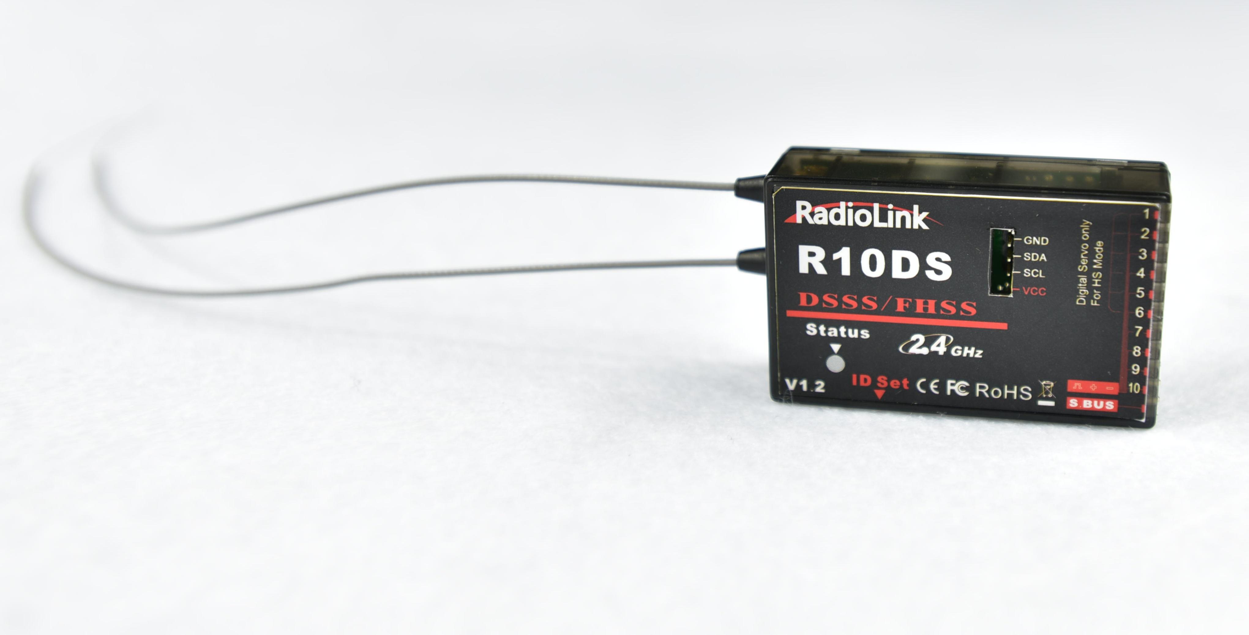
Radiolink R10DS, 2.4G 10 channels receiver, DSSS and FHSS spread spectrum working synchronously, use for Radiolink transmitters AT9, AT9S,AT10 and AT10II. SBUS and PWM signal possible working at the same time.
Two signal working mode:
Red LED always, SBUS and PWM signal working at the same time, 10 channels totally.
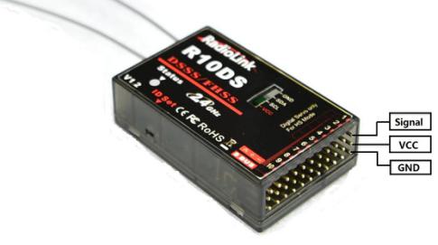
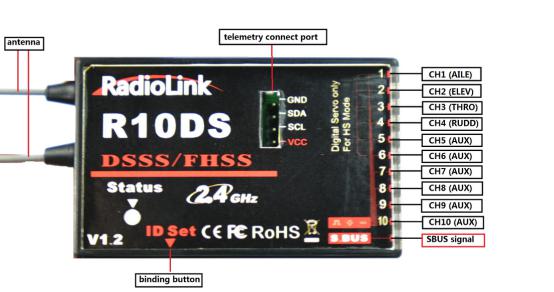
(1) PWM signal output: PWM signal output from row 1 to row 10(CH1 to CH10).
(2) SBUS signal output : row eleven support SBUS signal output.
How to match code with transmitter:
1. Place the transmitter and the receiver close to each other within 1 meters.
2. Turn on the transmitter, then power on the R10DS.
3. Connect CH3 of R10DS to ESC.
4. There is a black button on the R10DS, use a thin stick press the button twice in two seconds and release, receiver light start blinking, after about 8 times blinking, match code success when receiver signal LED always on!
Installment of receiver antenna:
1.The antenna must be kept as straight as possible. Otherwise it will reduce the effective range.
2.Large model aircraft may of some metal part interfering signal; in this case the antennas should be placed at both sides of the model. Then the best RF signal condition is obtained at any flying attitude.
3.The antennas must be kept away from conductive materials, such as metal and carbon by at least a half inch. The coaxial part of the antennas does not need to follow these guidelines, but do not bend it in a small radius.
4.Keep the antennas away from the motor, ESC, and other noise sources as much as possible.
5.Press and hold the Easy Link (ID SET) one second, now the receiver starts work.
6.After all of the above steps finished, the LED indicator will turn and keep in red.
7.The receiver can be packed by sponge or foam for shocking proof when it is installed to the model.
After all of the above steps finished, turn off the transmitter and then power it on, now the program functions to assure it under control of transmitter with a right connection.
Connect to telemetry module PRM-01


 Radiolink FQA