
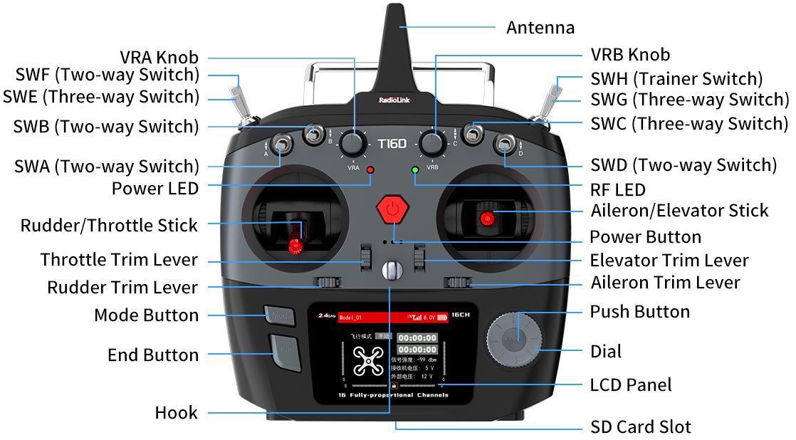
1.2.3 T16D Overview
Take Mode 2 as an example:
Note:
1.If the external module is selected in Receiver settings--RF SETTINGS, the green RF LED is off.
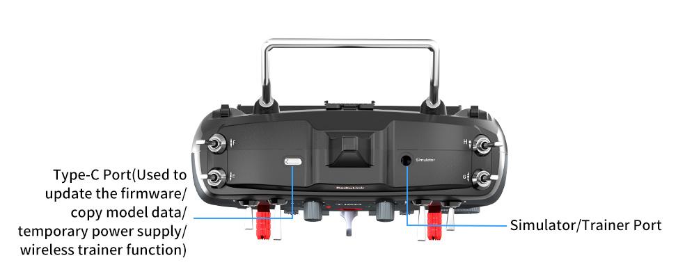
2.The type-C port of T16D can be used to update the firmware, copy model data and temporarily supply power to T16D. When the battery is dead, you can connect the power supply device such as a mobile power bank or a computer to the USB Type-C port to supply 5V power to T16D, and then long press home button to power on T16D. The maximum input voltage of the Type-C port of T16D is 5V.
3.If you use the Type-C port to temporarily power the T16D, please first remove the battery from the T16D battery compartment.
1.2.4 Transmitter Basic Operation
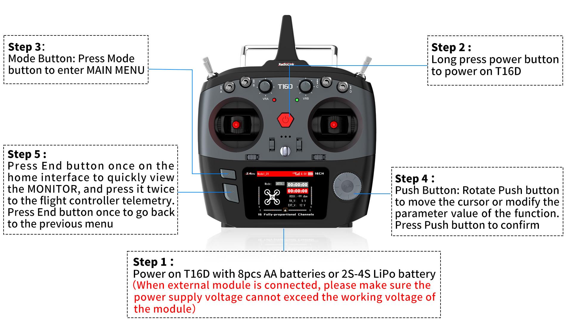
1.2.5 Power on T16D
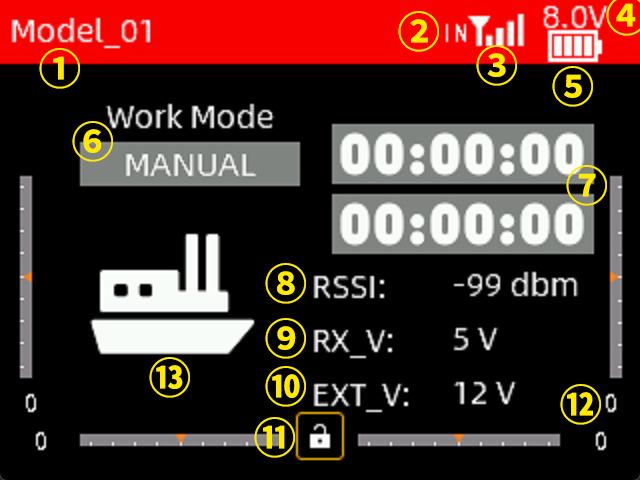
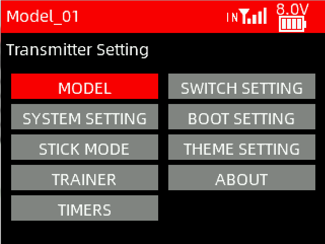
Long pressing the power button of T16D to turn it on, the screen will display as shown below:
① The name of the current model. You can select different models in Transmitter Settings - MODEL interface. T16D can support up to 100 sets of model storage. Before operating the model, be sure to check whether the model on the screen is consistent with the actual model used. If you select the wrong model, the movement, direction and neutral position settings of the servo will be wrong. Operating the remote control at this time may cause damage to the model.
② Module selection. It can be set in Receiver settings--RF SETTINGS interface. When internal module is selected, IN is displayed here  ; when external module is selected, EX is displayed here
  .
.
③  Signal tower logo. After the transmitter and receiver are successfully bound, the signal tower will be displayed on the screen of T16D. This logo can show the signal strength between the transmitter and the receiver.
④ Battery voltage of the transmitter.
⑤ Current power display.
⑥ Current flight mode.
⑦ Timer 1 and Timer 2. Move the cursor to timer 1 or timer 2, short press the Push button to start or stop timing, and long press the Push button to reset.
⑧ Received Signal Strength Indication. "NULL" means there is no signal or the receiver and transmitter have not been successfully bound. The closer the RSSI value is to 0, the stronger the signal. The larger the negative RSSI value, the weaker the signal.
⑨ The power supply voltage of the receiver;
⑩ Power battery voltage on the model. When using a receiver with a telemetry function and the telemetry cable is correctly connected, the external voltage will be displayed on the screen of the transmitter.
⑪ Screen lock. Move the cursor to the lock and long press the Push button to lock or unlock the screen. When the screen is locked, the lock is red. At this time, the Push or Mode button will not work, but you can short press the End button to quickly view the monitor interface. Long press Push button to unlock the screen, the lock will turn white, and all button functions will be restored.
⑫ Take mode 2 as an example. There are four scale marks on the bottom and left and right edges of the screen. When controlling a fixed-wing model, these scale marks represent the trim of aileron, elevator, throttle and rudder respectively, corresponding to the four trim levers on the transmitter (refer to 1.2.3 Overview). Be careful not to use this trim when debugging the model before its first flight. This trim is suitable for fine-tuning the attitude of the model when it is flying horizontally during its first operation.
⑬ The current model type.
1.2.6 Language Select
The menu interface is available in multiple languages, including Chinese, English, German, French, Russian, Japanese, Spanish, Korean, Thai and Polish. The menu language of T16D is English by default, You can select any other language you want.
Turn on T16D. Short press Mode button to enter MAIN MENU--Transmitter Settings--SYSTEM SETTING--LANGUAGE, and then select the language you want.

1.2.7 Transmitter Low Voltage Alarm
Transmitter low battery voltage alarm is 6.6V by default. If the battery voltage of transmitter is lower than 6.6V, T16D will make a voice broadcast to warn you the voltage is low. The battery voltage alarm value can be set based on the actual battery used.
Turn on T16D. Short press Mode button to enter MAIN MENU--Transmitter Settings--SYSTEM SETTINGS--BATTERY ALARM, and then set the alarm voltage according to your needs. If you use a 2S LiPo battery to power for T16D, it is recommended that the battery alarm voltage be no less than 7.4V; If you use a 3S LiPo battery to power for T16D, it is recommended that the battery alarm voltage be no less than 11.1V.
1.2.8 Flight Controller Telemetry
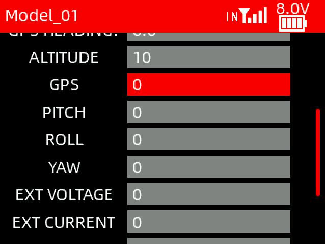
After powering on T16D, press End button once on the home interface to quickly view the MONITOR, and press it twice to the flight controller telemetry(See picture below).
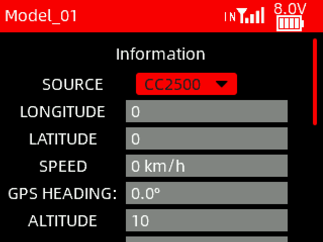
Before receiving the telemetry information, please select the correct source based on the following information:
①CC2500: Select CC2500 when Mavlink port of the R16F receiver is used to communicate with the flight controller;
②External: Select External when the T16D is connected to an external module;
③RX CRSF: Select RX CRSF when the FHSS V2.1 protocol is selected on T16D, and the R16F is in CRSF working mode (green light) to connect to the TELEM port of the flight controller.
Note: The difference between③and①is that③does not require the connection of the Mavlink port on R16F receiver. However, after connecting the Mavlink port of the R16F to the TELEM port of the flight controller, the prearm failure prompt of the flight controller can be displayed on the screen of T16D, and it can also be used to send commands on the bait boat function. If the above functions are needed, even if the source is selected as RX CRSF, the Mavlink port of the R16F can still be connected to the flight controller.
The tutorial of flight controller telemetry function:
https://www.youtube.com/watch?v=WRdfBEp7-RE
Here are the connection and setups when different source is selected:
①CC2500
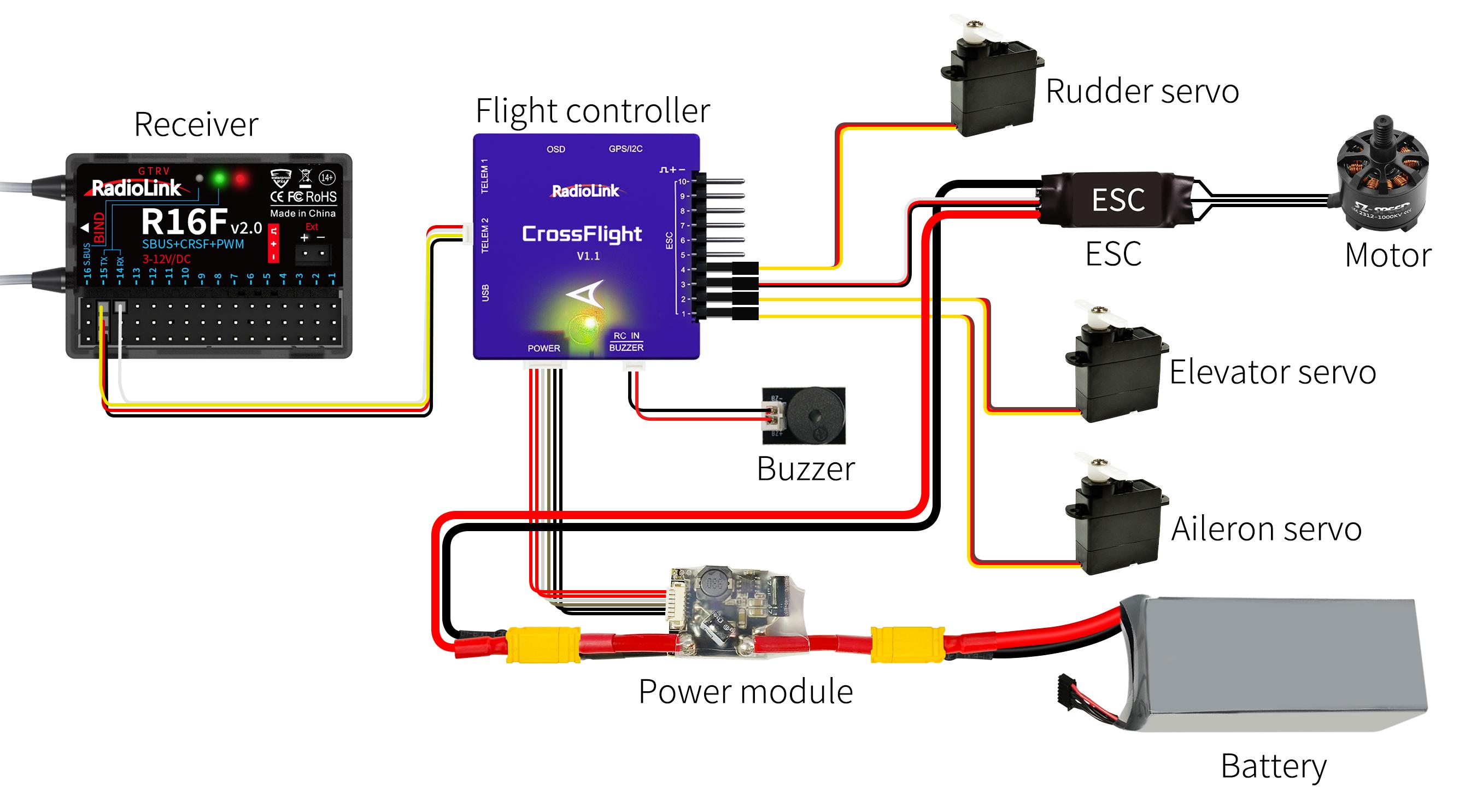
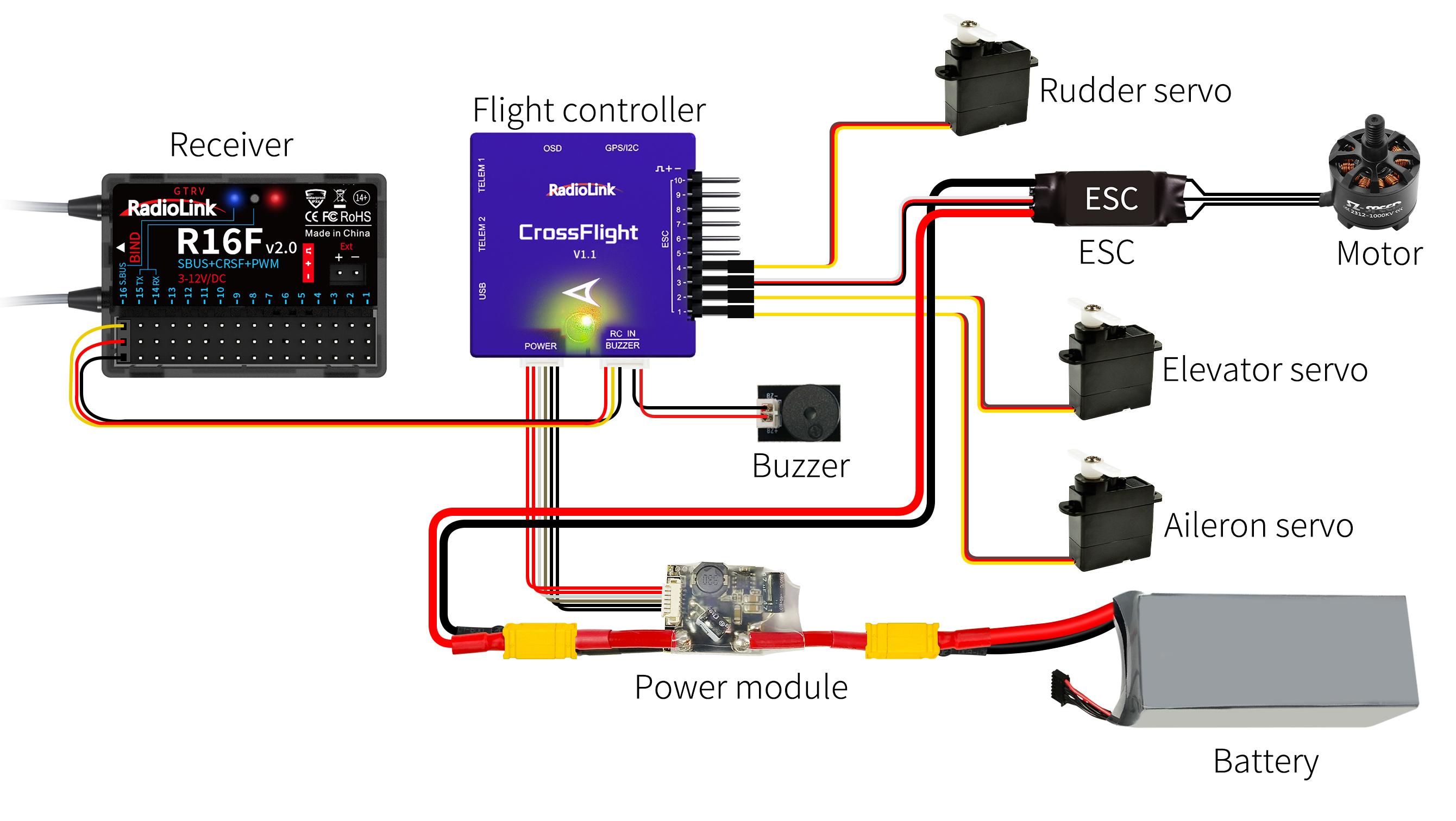
When T16D works with a flight control and a GPS, connect the Mavlink port of R16F to the TELEM port of the flight control. Take TELEM1 as en example (R16F comes with the below connect cable):

Then, please set the following 3 parameters in Mission Planner :
Set SERIAL1_BAUD to 57
Set SERIAL1_OPTIONS to 0
Set SERIAL1_PROTOCOL to 2
When GPS signal is searched successfully outdoors, the telemetry information will be displayed on thescreen of T16D.
②External
If external module is mounted, no need to set parameters in Mission Planner, and the flight controller information can be returned on the screen of T16D. For more details on how to use the external module, please refer to Chapter 5.1 RF SETTING.
③RX CRSF
Switch the working mode of R16F to CRSF working mode and connect it to CrossFlight. Take TELEM1 as en example.
Note: For more information about the working modes of R16F, please see Chapter 1.3.4 Receiver Working Mode.
Then, please set the following 3 parameters in Mission Planner:
Set SERIAL2_BAUD to 115
Set SERIAL2_OPTIONS to 0
Set SERIAL2_PROTOCOL to 23
When GPS signal is searched successfully outdoors, the telemetry information will be displayed on thescreen of T16D.
1.3 R16F Introduction
1.3.1 Features of R16F
T16D transmitter comes with a R16F, 16 channels receiver, with model voltage telemetry supported. 2.4G FHSS spread spectrum algorithm and 67-channel pseudo-random frequency hopping make the R16F get excellent anti-interference performance. R16F supports three signal outputs: PWM, SBUS and CRSF.
Note: Please do the following safety check before operating your model:
RSSI test (Received Signal Strength Indicator). For test method, please refer to the manual Chapter 1.3.7 RSSI Testing.
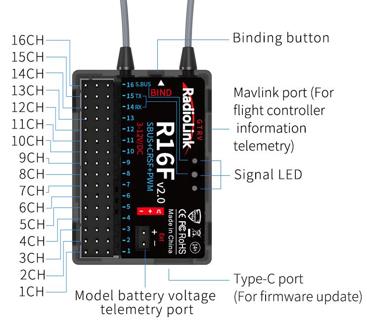
Antenna inspection: The gray line on R16F is coaxial cable, while the transparent line with a length of about 4-5 centimeters at the top is antenna. If the transparent line is broken or damaged, it will directly affect the control distance. If any abnormality is found, please replace the receiver antenna in time.
1.3.2 Binding
 T16D and R16F have finished binding by default. Turn on T16D and R16F. The signal tower will show on the top of the screen as the picture on the right, which means the transmitter and receiver has finished binding.
But if you buy a new R16F receiver for your T16D. You need to bind the receiver to the transmitter. Each receiver has an individual ID code and must bind with transmitter before using. When the binding is done, the ID code will be stored in the transmitter and there's no need to rebind.
Binding steps:
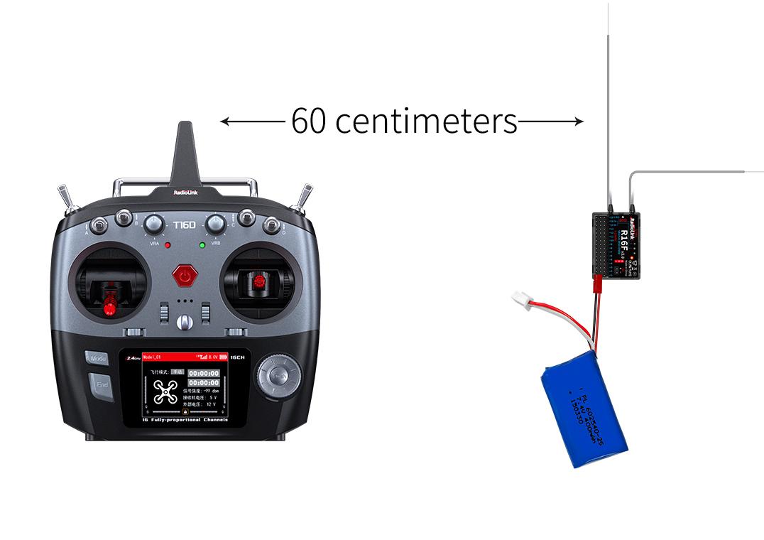
Put the transmitter and the receiver close to each other (about 60 centimeters). Note: The close distance of the transmitter and receiver may cause signal block, which leads to unsuccessful binding or signal loss.
Turn on the transmitter and the receiver, and the LED of R16F will start flashing slowly.
There is a black binding button (ID SET) on the side of receiver. Press the button for more than 1 second and release, the LED will flash quickly, indicate binding process is ongoing.
When the LED stops flashing and is always on, binding is complete and there will be a signal tower shown on top of the LCD screen of the transmitter. If not succeed, the LED will keep flashing slowly to notify, repeat the above steps.
T16D and R16F binding tutorial: https://www.youtube.com/watch?v=k-TGPy9AsNU
1.3.3 Receiver Connection
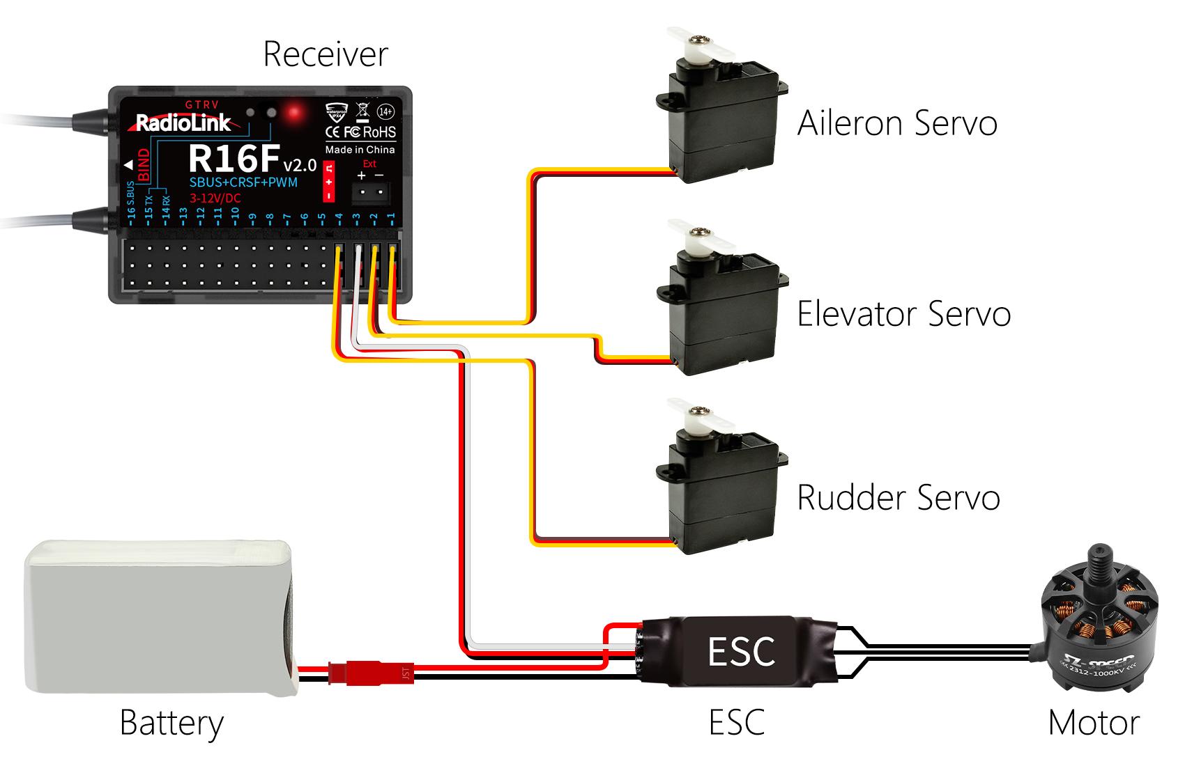
Connect Cable
Picture 1 Picture 2
 The connection wire for the receiver is shown in the picture above. The common ones are white/red/black wire (Picture 1) or yellow/red/brown wire (Picture 2). The two types of servo cables both are light-colored wire as the signal wire, and dark-colored wire as the ground wire, and the middle is 5V power supply, and the three wires correspond to " ".
Note: RadioLink receivers are all designed with anti-polarity connect protection. When the receiver is powered by a separate battery, the receiver will not be damaged if the battery polarity is reversed, but if the servo is connected at this time, it will damage the servo.
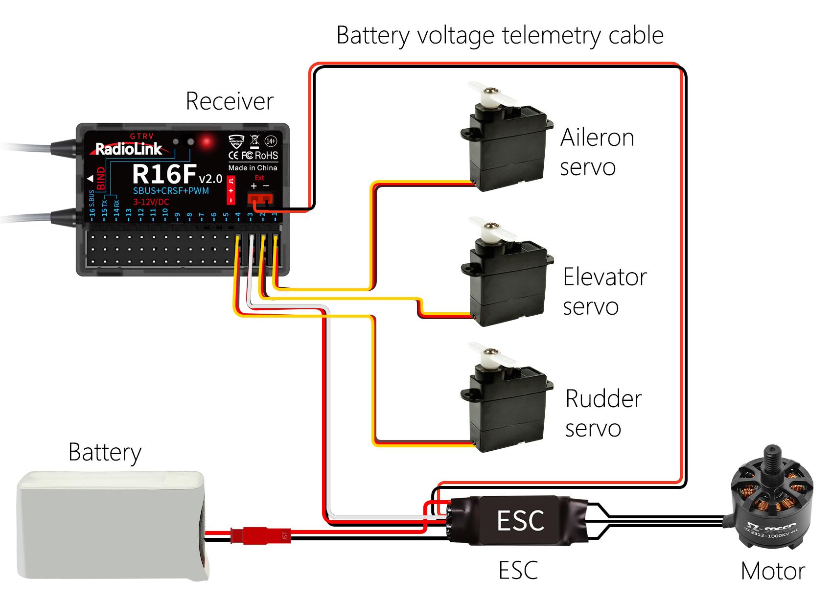
Model Battery Telemetry connection
R16F supports telemetry of model battery voltage, receiver voltage and RSSI. Connect one end of the telemetry cable to the R16F telemetry port, and the other end to the ESC to return the power battery voltage. Please refer to the below picture for connection of the telemetry cable:
Attention:
Reverse polarity protection circuit design for all 16 channels of R16F ensures vital components are protected from a reverse polarity connection. But the JST connector which packed with R16F for connect to battery cannot reverse polarity connect, or it will lead to the wrong voltage value telemetry.
Ext port is only used to model voltage telemetry. It can not be used to power the receiver.
1.3.4 Working Modes
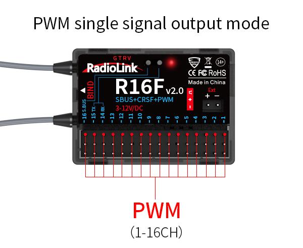
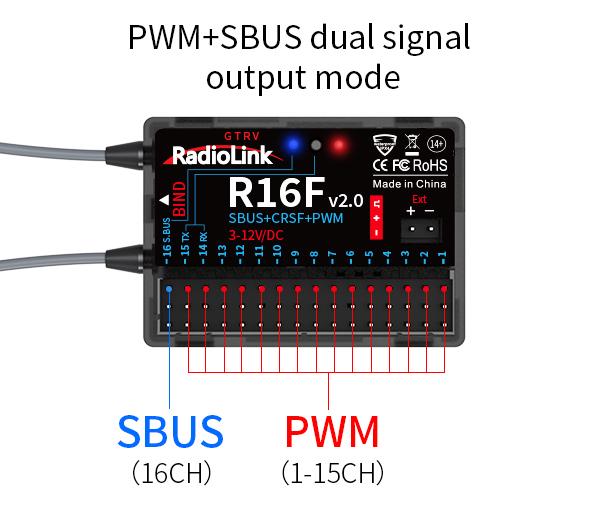
R16F supports three signal outputs: PWM, SBUS and CRSF. It has four working modes in total.
R16F working modes setting:
Turning on/off the SBUS: Short press the binding button once to turn on/off the SBUS. Blue LED indicates the SBUS is turned on, and channel 16 outputs SBUS signal.
Turning on/off the CRSF: Short press the binding button twice within 2 seconds to turn on/off the CRSF. Green LED indicates the CRSF is turned on. Channel 14 receives RX and channel 15 outputs TX.
Introduction of the four working modes:
PWM working mode
Red LED always on indicates PWM signal output, 16 channels in total.
PWM+SBUS working mode
Red and blue LED always on indicates PWM+SBUS signals output.
CH1 to CH15 output PWM signal output while CH16 outputs SBUS signal.
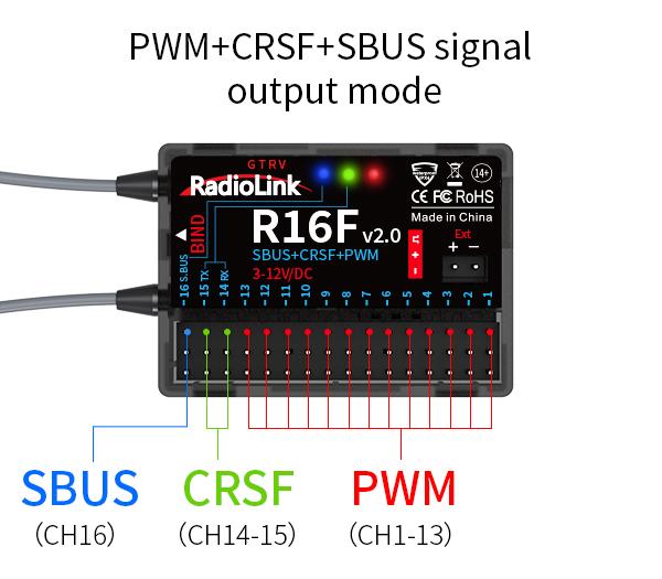
PWM+CRSF+SBUS working mode
Red, green, and blue LED always on indicates PWM+CRSF+SBUS signals output.
CH1 to CH13 output the PWM signal, CH 14 receives RX, CH15 outputs TX, and CH16 outputs the SBUS signal.

PWM+CRSF working mode
Red and green LED always on indicates PWM+CRSF signals output.
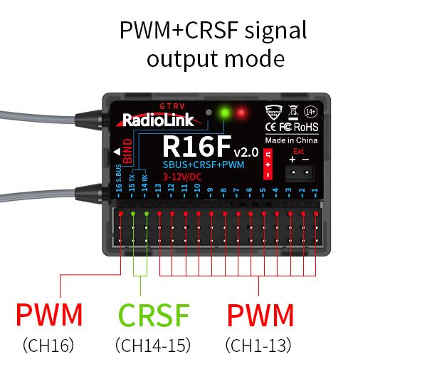
CH1 to CH13 output the PWM signal, CH 14 receives RX, CH15 outputs TX, and CH16 outputs the PWM signal.
1.3.5 Receiver Firmware Update
R16F supports firmware upgrade. The steps for firmware upgrade are as follows:
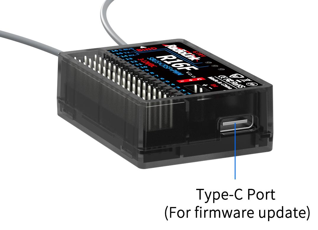 Plug a Type-C cable into the Type-C port of R16F.
Press and hold the binding button of R16F.
Plug the other end of the Type-C cable into the computer and release the binding button.
The LED of the receiver is on, and a USB flash drive appears on the computer.
Copy and paste the new firmware of R16F into the USB flash drive to complete the update.
R16F firmware update tutorial: https://www.youtube.com/watch?v=VkRftk5fYP0
1.3.6 Installment of Receiver Antenna
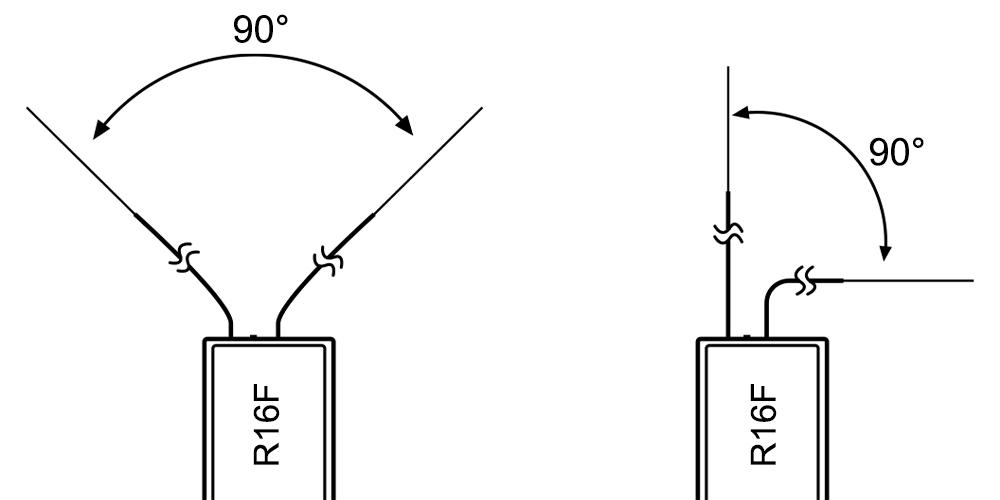
It is important to install the receiver antenna correctly on the model, because wrong receiver antenna installation will cause poor signal quality.
How receiver antenna installation affects signal quality? Here are the common mistakes when installing the antennas:
The two antennas of the receiver CANNOT overlap, because they will interfere with each other. Keep the two antennas at a 90-degree angles. (As shown on the right)
Antennas should NOT be placed near metal objects, because reflection of the conductor panel will drastically worsen the signal.
Do NOT keep antennas parallel to the ground. It should be placed vertically to the ground.
Big models may contain metal parts that influence signal emission. In this case. antennas should be positioned at both sides of the model to ensure the best signal status in all circumstances.
Antennas should be kept away from metal conductor and carbon fiber at least half inch away and no over bending.
Keep antennas away from motor, ESC or other possible interference sources.
Sponge or foam material is advised to use to prevent vibration when installing receiver.
Receiver contains some electronic components of high-precision. Be careful to avoid strong vibration and high temperature.
Special vibration-proof material for R/C like foam or rubber cloth is used to pack to protect receiver. Keeping the receiver in a well sealed plastic bag can avoid humidity and dust, which would possibly make the receiver out of control.
Refer to the following link to view the guide on antenna installation of R16F:
https://www.radiolink.com/newsinfo/886600.html
1.3.7 RSSI Testing
 If the control distance is short, please refer to this instruction to test the transmitter. This instruction will introduce the test procedure of the transmitter RSSI value and the solution to the abnormal RSSI value.
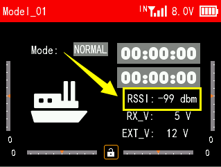
Turn on the transmitter and power on the receiver at the same time, and then the transmitter and receiver will be connected (if not connected, you need to bind again). The signal tower appears on the transmitter interface, indicating that the binding is successful. The value of RSSI will appears on the home page, and the RSSI value will keep changing according to the distance between the transmitter and the receiver. (As shown on the right)
Make the receiver antenna and transmitter antenna parallel. Keep transmitter apart from receiver about 60 centimeters and both antennas straight. It is normal that RSSI value is within the range of 0 to -30dBm. The closer the value is to 0, the stronger the signal is. (As shown below)
Here is the tutorial of RSSI testing of T16D:
Abnormal signal strength solution:
Check whether the antennas of the receiver and transmitter are damaged. Most signal strength degradation is caused by antenna damage. If it is damaged, the antenna needs to be replaced. If there is no damage, you can test the transmitter and receiver for malfunctions by replacing the receiver. If still cannot solve the problem, email to after_service@radiolink.com.cn to get support.
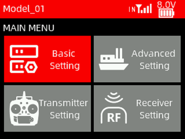
Chapter 2 Basic Setting
This chapter introduces all the functions in the [Main Menu]--Basic Setting.
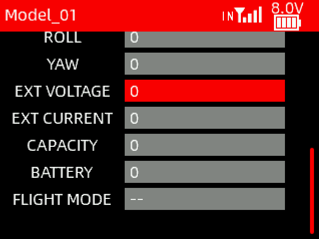
2.1 MONITOR
To display the real-time output status of all channels, you can monitor the current output status of all channels.
Note:
Note: Short press End button on the main interface of T16D to quickly view channel monitor.
2.2 REVERSE
 You can perform the reverse processing of the output data of one channel or more channels. This function is used in the debugging of a model.
Models may follow different standards in the design. In the assembly and debugging of a model, if you find that the operation model is opposite to the required direction, for example, the model goes to the left when you want the right direction, the output signal direction of the transmitter needs to be adjusted at this time. The function is used to adjust the action direction of output signals of each channel.
Move the cursor to the channel that needs to be modified, and short press Push button to switch the direction.
2.3 END POINTS
Adjust the travel amount of the servo output. This function is used in debug. This function can be used to set the travel amount of the HIGH, LOW and SUBTRIM at both ends of the channel respectively.
When the model is designed, there are changes in the size of the structure and the specification may not be unified. In addition, there may be different sizes of operator's habitual actions. The servo travel function can be used to set the travel amount required for each channel to adjust the corresponding structure for the best match, to obtain the required operation effect. For example, you want to operate that the turning action is not so large, you can adjust the value of the direction channel at both ends to be smaller. In this way, the turning action should be smaller, with less likely to be tailspin.
Move the cursor to the end point value that needs to be set, and rotate Push button to set the appropriate value. The end point can be set from 0 to 120.
The tutorial of END POINT function: https://www.youtube.com/watch?v=SYsrEZqgJM8
2.4 CH SPEED
CH SPEED (channel speed) function can be used to adjust the output speed of some channels for a specific model. For example, in the landing gear retraction, users may want it to be opened slowly, therefore, you can slow down the output speed of the corresponding channel.
SWITCH: A switch can be set to control the function. You can assign SWA, SWB, SWC, SWD, SWE, SWF, SWG and SWH. NULL means no switch assigned.
STATE:
INH: This function is not enabled.
ON/OFF: Turn on/off this function.
Channel speed defaults to 0 seconds, which means no channel delay. Channel speed can be set up to 12 seconds.
2.5 AUX CH
AUX CH(auxiliary channel) function is used to assign the control switches for CH5 to CH16. You can set SWA, SWB, SWC, SWD, VRA, VRB, VRC and VRD. NULL means no switch assigned.
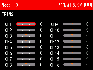
2.6 TRIMS
The function is used to correct mechanical errors, and adjust the neutral position of each channel. The trim of each channel defaults to 0. -100 to 100 can be selected.
2.7 PROG.MIX
This transmitter provides up to 32 groups of mixing. Mixing can help to control two channels simultaneously with one switch.
Tutorial of PROG.MIX: https://www.youtube.com/watch?v=6Mb0TP4BiNk
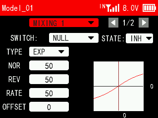
PROG.MIX 1/2
SWITCH: The switch to control this group of mixing. You can assign SWA, SWB, SWC, SWD, SWE, SWF, SWG and SWH. NULL means the function is enabled by default.
STATE:
INH: The mixing is not enabled.
ON/OFF: Turn on/off the mixing.
TYPE: EXP, VTR and CRV.
NOR: To adjust the end point ratio on the right side of the slave channel. For example, if the NOR is set to 50, then when operating the master channel, the end point of the slave channel on the right side is only 50% of the master channel. The adjustment range is between -100 and 100. A positive number indicates that the slave channel and the master channel move in the same direction, and a negative number indicates that the slave channel and the master channel move in opposite directions.
REV: To adjust the end point ratio on the left side of the slave channel. For example, if the NOR is set to 50, then when operating the master channel, the end point of the slave channel on the left side is only 50% of the master channel. The adjustment range is between -100 and 100. A positive number indicates that the slave channel and the master channel move in the same direction, and a negative number indicates that the slave channel and the master channel move in opposite directions.
RATE: Set the EXP, VTR, CRV curve rate of the slave channel. The adjustment range is between -100 and +100.
OFFSET: Set the central point of the slave channel.
 PROG.MIX 2/2
MASTER: Master channel that controls the slave channel.
SLAVE: Slave channel that is controlled by the master channel.
LINK: It decides whether the functions on the master channel work on the slave channel. If LINK is turned on, when operating the master channel, the functions set for the master channel will work on both the master channel and the slave channel.
TRIM: It decides whether the trim of the master channel works on the slave channel. If TRIM is turned on, when operating the master channel, the trim of the master channel will work on both the master channel and the slave channel.
T16D PROG.MIX function tutorial: https://youtu.be/6Mb0TP4BiNk
2.8 SWITCH AUDIO
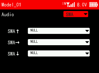 This function can be used to set the voice broadcast function of SWA, SWB, SWC, SWD, SWE, SWF, SWG and SWH. When users assign these switches to control a certain function, they can set the switch to broadcast different voices at different positions. The function is often used to broadcast different flight modes, or to broadcast the on or off of a certain function.
Users can customize the voice switch. Just copy their voice file to the transmitter. For voice production methods, please refer to Chapter 7 Customized Switch Voice Production.
2.9 SENSOR BROADCAST
This function can be used to set the voice broadcast of telemetry information, including signal strength, RX Vol (receiver voltage), EXT Vol (external voltage) and BAT Vol(transmitter voltage).
The broadcast switch can be set to SWA, SWB, SWC, SWD, SWE, SWF, SWG and SWH. NULL means voice broadcast is turned off.
There is an option to turn it on or off, which is used to select whether to broadcast the current telemetry information. A white dot on the left indicates off, and the dot on the right indicates on.
For example: If you set the broadcast switch to SWA_UP, push SWA up and the transmitter will broadcast signal strength, receiver voltage, external voltage and transmitter voltage in sequence.
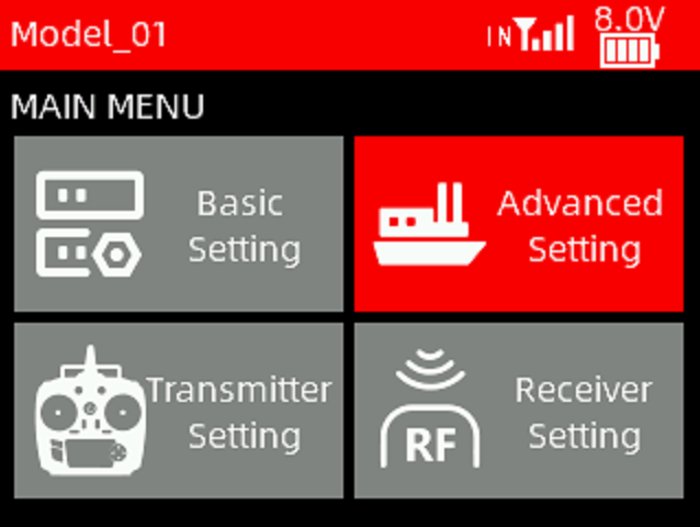
Chapter 3 Advanced Settings
This chapter introduces all the functions in the menu Advanced Settings, including TYPE SELECT, FLIGHT MODE, CONDITIONS, RATE/CURVE, THROTTLE CURVE, THROTTLE HOLD, V-TAIL etc. When selecting a model type, the functions applicable to that model type will appear under the advanced settings menu. For example: when the model type is selected as a helicopter, PITCH CURVE and HELICOPTER SETTINGS function will appear.
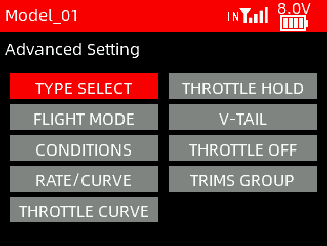
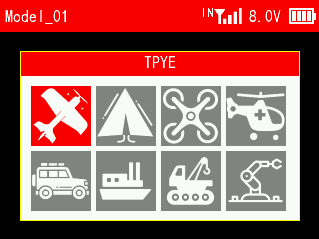 3.1 TYPE SELECT
This function is to select the type of the current model. T16D supports 8 model types including fixed-wing, delta wing, multi-rotor, helicopter, car, boat, tank and robot. When selecting a different model, the functions applicable to that model type will appear under the advanced settings menu.
3.2 FLIGHT MODE
Flight mode is used to set and switch among different flight modes, including NORMAL, ATTI, GPS, HOVER, F/S, AUX, ARCO, AUTO, CIRCLE, DRIFT, GUIDED, P.HOLD, RTL, SIMPLE, SPORT, STABL., and LAND etc.
This function needs to be used in conjunction with the flight controller. It is mostly used to switch among different flight modes of the flight controller after the model is connected to the flight controller. Match the mode name in the transmitter with the flight mode set in the flight controller, so as to avoid accidental damage and injury caused by errors when changing the flight mode of the flight controller.
Flight Mode 1/2
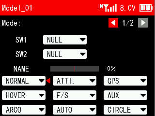 SW1/SW2: Both SW1 and SW2 are switches for flight mode. SWA, SWB, SWC, SWD, SWE, SWF, SWG and SWH can be selected. SWA, SWB, SWC, SWD, SWE, SWF, SWG and SWH can be customized as a 2 position switch or a 3 position switch in Switches Settings menu under Transmitter Settings. You can set only 1 switch or set 2 switches at the same time. If only 1 switch is set, the transmitter can only switch between 2 flight modes; If 2 switches are set at the same time, the transmitter can switch up to 9 flight modes.
Move the cursor to the name of the flight model, press the Push button and then turn the Push button to select the flight mode. After setting the mode button, you can toggle the switch. The small red triangle after the flight mode indicates the current flight mode at the current position of the switch.
Flight Mode 2/2
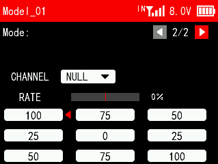 CHANNEL: The control channel of flight mode, which can be set from channel 5 to channel 16. After the output channel is set, you can toggle the switch to view the channel output value on the current interface.
RATE: The ratio corresponding to each posture will determine the value output by the posture selection channel when switching to this posture mode. The settable range is -100 to +100.
Move the cursor to the ratio value, short press the Push key and then turn Push to set the ratio. When setting different ratios for each mode, try to avoid setting the ratios of different postures too close, so that the flight control can more accurately identify the posture to be switched. After the ratio setting is completed, you can toggle the switch. The small red triangle after the ratio corresponds to the ratio value of the current flight mode of the switch.
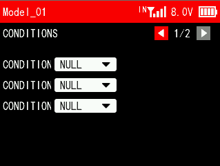 3.3 CONDITION
CONDITION 1/2
Up to three conditions can be set in a model, and up to three switches can be used to switch conditions.
 CONDITION 1/CONDITION 2/CONDITION 3: SWA, SWB, SWC, SWD, SWE, SWF, SWG and SWH can be selected to switch conditions. Multiple switches can be used to switch conditions. Condition priority: 3>2>1.
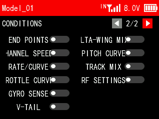
CONDITION 2/2
A list of functions that can be turned on or off using conditional switches, including END POINTS, CHANNEL SPEED, RATE/CURVE, THROTTLE CURVE, GYRO SENSE, V-TAIL, DELTA-WING MIX, PITCH CURVE, TRACK MIX and RF SETTINGS.
If you need to use conditional switches to control the above functions, please turn on the corresponding functions on this interface, otherwise the conditional switches will not take effect.
For example: if users needs to use one switch to control 3 different throttle curves, please set it as these steps below:
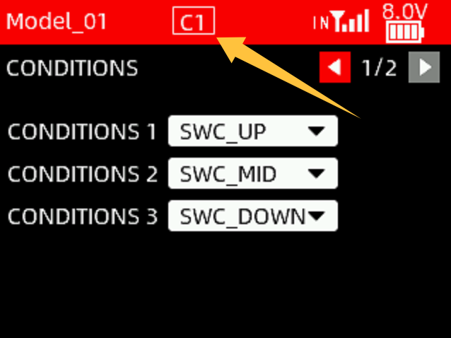
(1) Set the switches of CONDITION 1/CONDITION 2/CONDITION 3 to SWC_UP/SWC_MID/SWC_DOWN respectively;
(2) Turn on THROTTLE CURVE function on the CONDITION 2/2 interface;
(3) Enter the throttle curve setting interface under the advanced settings menu, push SWC up, which is condition 1, and set the first throttle curve; push SWC to the middle, which is condition 2, and set the second throttle curve; push SWC down, which is condition 3, and set it to the third throttle curve. Flip the SWC to switch between different throttle curves. When the SWC condition switch is placed in different positions, the top taskbar will also display the corresponding condition number (see the picture on the right).
T16D condition function tutorial: https://www.youtube.com/watch?v=I9FWLX-rsRo
3.4 RATE/CURVE
The function is used to adjust the sensitivity of servo in the left and right side, so that its action changes into linear or non-linear.
CHANNEL: Channel 1, Channel 2 and Channel 4 can be set.
TYPE: EXP, VTR and CRV can be set.
EXP:
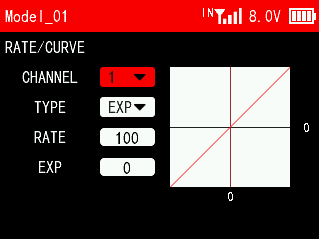 RATE: The ratio of the actual output value of the joystick to the original value of the joystick. For example: when the rate is set to 50, it means that when the joystick is at the left and right ends, the actual output of the joystick is 50%. The rate can be set in the range from -100 to +100, and the plus and minus represent the opposite directions of the servo.
EXP: Adjust the sensitivity of the joystick at both ends of the neutral position. When the curve is set to a negative value, the greater the negative value, the lower the sensitivity of the joystick in the neutral position and the higher the sensitivity at both ends; when the curve is set to a positive value, the greater the positive value, the lower the sensitivity of the joystick in the neutral position. The higher the sensitivity in the neutral position, the lower the sensitivity at the ends. The settable range of is from -100 to +100.
VTR:
RATE: The ratio of the actual output value of the joystick to the original value of the joystick. For example: when the rate is set to 50, it means that when the joystick is at the left and right ends, the 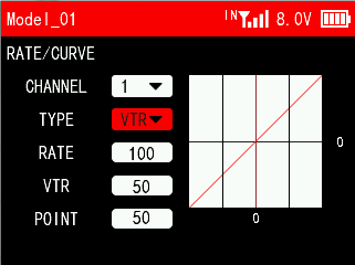 actual output of the joystick is 50%. The rate can be set in the range from -100 to +100, and the plus and minus represent the opposite directions of the servo.
VTR: The output range in the first half of the stroke is the current set value, and the output range in the second half of the stroke is 100/-100 minus the current set value. The settable range of the curve is from -100 to +100, and the positive and negative values represent the opposite direction of the servo.
POINT: the critical point of the VTR curve. The settable range is from 0 to 100. For example: when the VTR is set to 30 and the point is set to 70, the value output by the first 70% of the joystick accounts for 30% of the original value of the joystick.
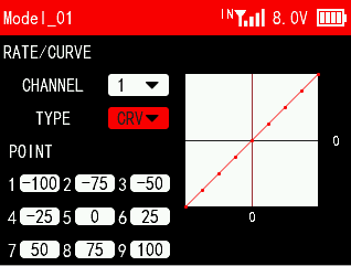
CRV:
Set a 9-point curve type from the lowest point to the highest point of the channel. For example, if point 1 is -100, it means that the travel amount of point 1 is -100, and if point 2 is -75, it means that the travel amount of point 2 is -75. The starting amount of each point is the marked position of the previous point.
3.5 THROTTLE CURVE
The throttle curve can make the throttle operation more sensitive or smooth during acceleration and braking, making the throttle action change linearly or non-linearly.
TYPE: EXP and CRV can be set.
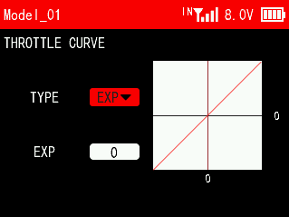 EXP:
EXP:
EXP: Adjust the sensitivity of the throttle from the center point to the high point. When the curve is set to a negative value, the greater the negative value, the lower the sensitivity of the joystick at 50% throttle, and the higher the sensitivity at low and high throttle positions; When the curve is set to a positive value, the positive value The larger it is, the more sensitive the joystick is at 50% throttle and the less sensitive it is at low and high throttle. The settable range of the curve is from -100 to +100.
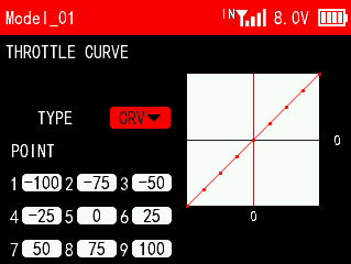
CRV:
Set a 9-point curve type from the lowest point to the highest point of the throttle. For example, if point 1 is -100, it means that the travel amount of point 1 is -100, and if point 2 is -75, it means that the travel amount of point 2 is -75. The starting amount of each point is the marked position of the previous point.
3.6 THROTTLE HOLD
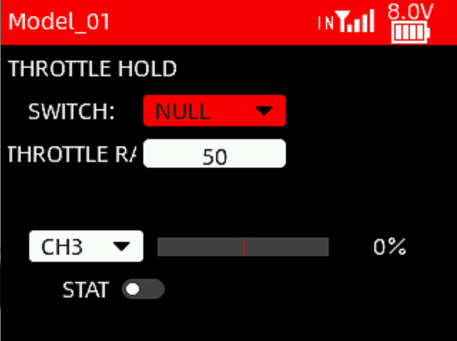 Throttle hold, or the cruise control function can set the throttle output to a fixed value. When the throttle hold is turned on, the throttle output will jump to the locked position regardless of the current throttle position. For example, when using a crawler, you can turn on the cruise control with a switch, and the crawler can maintain a constant speed without touching the trigger.
SWITCH: SWA, SWB, SWC, SWD, SWE, SWF, SWG or SWH.
Note: When setting the control switch, you can directly toggle a certain switch to directly select that switch as the control switch. However, before toggling the switch, please be sure to set the throttle rate to 0 to avoid accidents caused by the activated throttle hold function.
THROTTLE RATE: Fixed output value of the throttle. The setting range is from -120 to +120, which means the servo output value of the throttle channel. When setting parameters, you can check the set throttle output value through the bar below.
CH3: The default throttle channel of channel 3, CH3. Users can choose any one channel from channel 1 to channel 16 as the throttle channel.
STATE: The current status of the throttle lock. A white dot on the left indicates off, and the dot on the right indicates on.
T16D throttle hold function tutorial: https://www.youtube.com/watch?v=RGXMy3x_Q5g
3.7 V_TAIL (Fixed-wing)
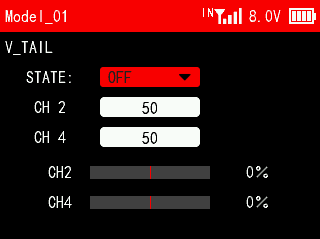 This function is set for some specific aircraft models, for example, fixed-wing aircraft with V-tail. You can perform mixing control for both channels in the same direction and reverse direction.
STATE: Turn on/off this function.
CH2/CH4: Adjust the values of CH2 and CH4 to determine the range and direction of the movement of the elevator or rudder servo in response to the elevator or rudder joystick.
3.8 THROTTLE OFF (Fixed-wing)
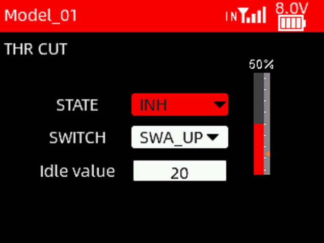 This function can keep the throttle of the fixed-wing aircraft's at idle speed.
STATE: Turn on/off this function.
SWITCH: A switch can be set to control the throttle off function. When this function is enabled, pushing the throttle stick to the lowest position will keep the throttle at idle speed.
Idle value: The idle speed value of the throttle.
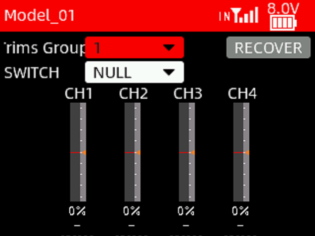 3.9 TRIMS GROUP (Fixed-wing)
This function allows you to set three groups of independent trim values for channels 1 to 4 of the fixed-wing aircraft. These three three groups of trim values can be different and will not interfere with each other.
Trim Group: Three groups can be set.
SWITCH: A switch can be set to change the trim groups.
Recover: Reset the current trim values to 0.
3.10 DELTA-WING MIX (Delta-wing)
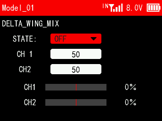 Delta-wing mix is also called elevon mix. It is commonly used in delta wing aircraft. Two servos independently control the two surfaces on the left and right sides of the aircraft, and they can work as both the ailerons and elevators.
STATE: Turn on/off this function.
CH1/CH2: Adjust the values of CH1 and CH2 to determine the range and direction of the movement of the aileron or elevator servo in response to the aileron or elevator joystick.
3.11 GYROSCOPE
The function is used to adjust the gyroscope sensitivity. When adjusting the gyro sensitivity, please make sure the receiver has a built-in gyroscope and the gyroscope function of the receiver is turned on.
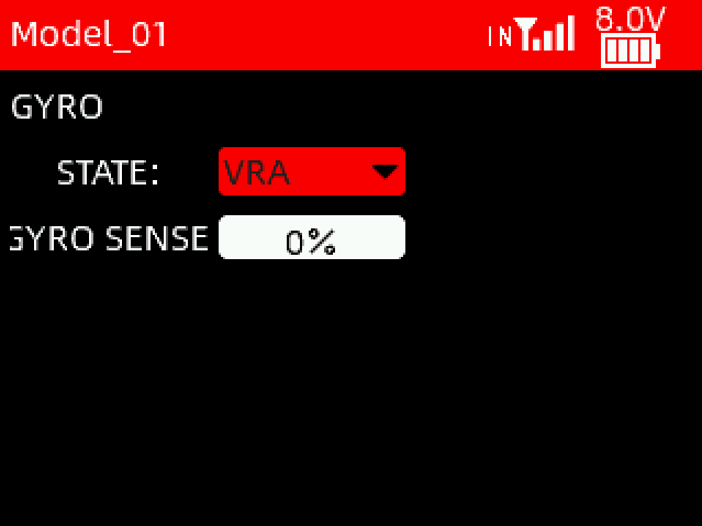 STATE: VRA and VRB knobs can be used to adjust the gyroscope sensitivity. When NULL is selected, the gyroscope sensitivity must be set manually.
GYRO SENSE: The sensitivity can be set from 1% to 100%. 100% means the strongest sensitivity. When set to off, the gyroscope is turned off.
Note: GYRO function is only applicable to FHSS V2 protocol receivers, including R8FGH, R8FG V2.1 version, R4FGM V2.1 version, and R8FG and R4FGM receivers with a factory date of 2023/4/26 or later. Other receivers do not support this function, but the gyro sensitivity can be controlled by channel 8. Assign a knob switch to control channel 8. Then the knob can be used to adjust the gyro sensitivity.
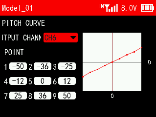
3.12 PITCH CURVE (Helicopter)
This function is set to adjust the helicopter's pitch motion curve to match the throttle output to achieve the best flight status of the helicopter.
OUTPUT CHANNEL: The output channel of the pitch curve. You can select channel 5 to channel 16. When the output channel is set to NULL, the function is not enabled.
POINT: The setting point of the pitch curve. A total of 9 points can be set, and the parameters can be set from -100 to +100.
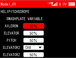
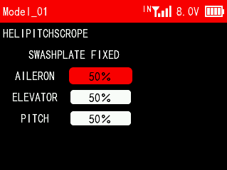
3.13 HELICOPTER SETTINGS (Helicopter)
The function is to set the mix control of the helicopter's aileron, elevator, and pitch servos in the current mode to achieve the best flight effect.
3.14 Bait Boat (Boat)
When selecting a car/boat model, you can set the bait boat function. You can get automatic navigation by using T16D with a flight control and a GPS. R16F comes with a Mavlink cable to connect to RadioLink CrossFlight flight controller TELEM1 port, which can be used to return all information about the boat and switch the working mode on T16D (Note: Working modes need to be set in advance in Mission Planner). For details of connection and setting, please refer to Chapter 1.2.8 Flight Controller Telemetry.
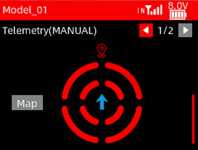
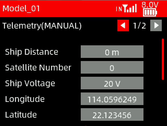
Telemetry 1/2
Ship distance: The distance between the boat and the starting point (Need to set the starting point first)
Satellite number: The number of satellites recognized by GPS. The greater the number, the more accurate the positioning.
Ship voltage: The voltage of the boat battery.
Longitude/Latitude: Used to display the real-time longitude and latitude of the boat.
The map below is used to show the boat's heading angle.
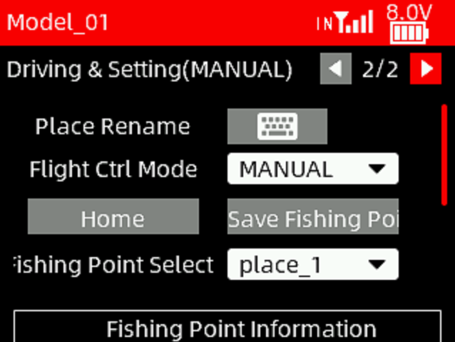
Driving and setting 2/2
Click the keyboard to modify the name of the current fishing spot.
Flight Ctrl Mode: There are three modes including MANUAL, ACRO and GUIDED.
 Manual mode: The steering and throttle joysticks of the transmitter directly control the throttle and steering output of the boat (car).
Cruise mode: The boat maintains a constant speed at 100% throttle and travels in a straight line without being disturbed by external forces (The direction can be changed by the joystick).
Guided mode: The boat will automatically drive to the fishing point selected.
Note: To switch the three modes on T16D, please refer to Chapter 1.2.8 Flight Controller Telemetry.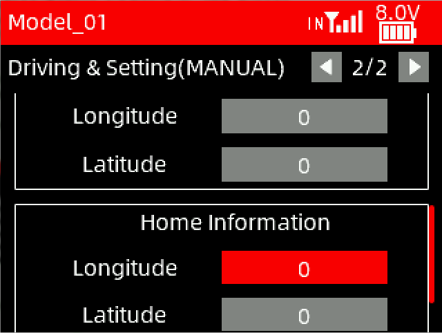
Home: Before the boat travels, you need to save the starting position (Home). After saving it, the latitude and longitude of the home position will be displayed in the home information below.
Save Fishing Point: Drive the boat to the designated location, select the fishing point number, and short press the PUSH button to save the current longitude and latitude. The longitude and latitude of the fishing point will be displayed in the fishing point information below.
Fishing Point Select: To select fishing points. Each fishing point can be renamed. Up to 100 fishing points can be saved.
Fishing point information: The longitude and latitude of the fishing point.
Home information: The longitude and latitude of the home.
Note: If the binding between the transmitter and receiver fails, no flight controller is installed on the boat, or the GPS connection fails, the transmitter will not be able to obtain the telemetry information of the menu interface, and a notice may pop up on the screen (see the picture on the right). Short press the End button to exit.
Bait boat setting steps:
Turn on the transmitter;
Turn on the boat's power supply and wait for the transmitter to connect to the receiver. After successful binding, the receiver light will stay on;
Check whether the functions of the joysticks and switches correspond;
Enter the bait boat setting menu in the transmitter and check the number of GPS satellites. 20 satellites means the positioning is relatively accurate, and more than 30 satellites means the error is centimeter level (the specific position is related to external factors, such as water flow, obstacles, etc.);
If the number of satellites reaches more than 20, enter the second setting page;
Drive the boat to the starting position, scroll the dial to "Home", and short press PUSH button to confirm it. The home position is used for return;
Select mode. You can select MANUAL, CRUISE or GUIDED (GUIDED mode cannot be selected when no fishing point is set);
Drive the boat to the designated fishing point, scroll the dial to "Fishing Point", and the location can be saved in the transmitter;
If you need to save multiple fishing spots, scroll the dial to "Fishing Spot Selection" and short press PUSH to confirm it. Then drive the boat to the second fishing spot and click "Save Fishing Spots". Repeat the above operations for subsequent fishing spots;
After saving the fishing point, you only need to set the starting point before setting off, and choose guided mode to reach the designated fishing point. When you want to pass multiple fishing spots in one voyage, you can switch to the next fishing spot after reaching the fishing spot, and the boat will automatically drive to the next destination. It will automatically return to home position when the signal is lost on the way, and you can also toggle SWD to activate the return-to-home function;
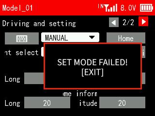
If "SET FAILED" pops up when setting the mode, the mode switching fails. That is because the command fails to be sent to the receiver. You can send it again to have a try.
3.15 TRACK MIX
This function is to set for some specific models, such as tank, excavator models. Two tracks can be driven in the same direction or in the opposite direction.
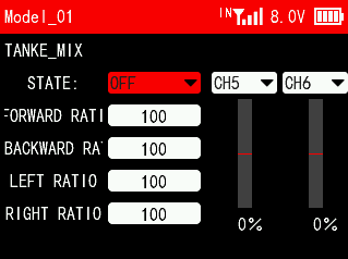 STATE: Turn on/off this function. You can select channel 1 to channel 16, which are determined by the receiver channels two motors connected to respectively. The default channels are CH5 and CH6.
FORWARD RATIO: The ratio of the throttle output value and the original throttle value of the two tracks moving forward.
BACKWARD RATIO: The ratio of the channel output value and the original channel output value of the two tracks moving backward.
LEFT RATIO: The ratio of the channel output value and the original channel output value of the two tracks turning left.
RIGHT RATIO: The ratio of the channel output value and the original channel output value of the two tracks turning right.
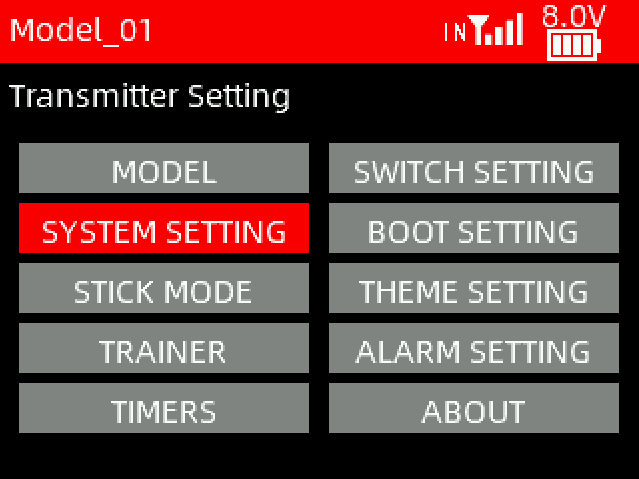
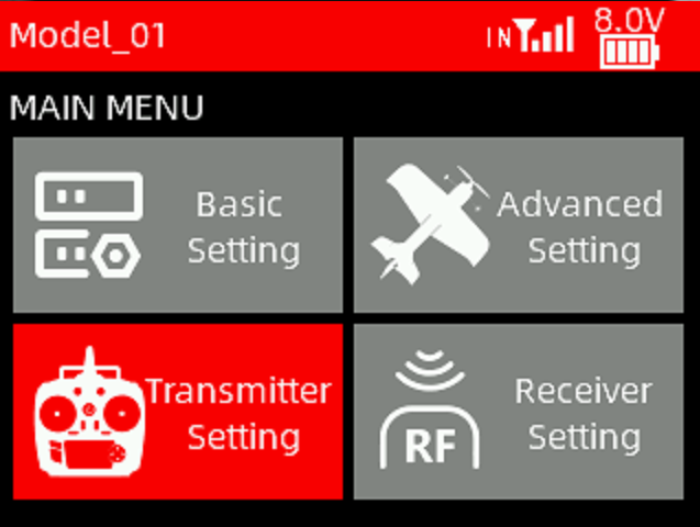
Chapter 4 Transmitter Settings
This chapter introduces all the functions in the menu Advanced Settings, including MODEL, SYSTEM SETTINGS, STICK MODE, TRAINER, TIMERS, SWITCHES SETTINGS, BOOT SETTING, THEME SETTING, and ABOUT.
4.1 MODEL
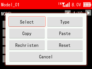
The MODEL menu is used for model management, including model select, model type, mode copy/paste, rename and model reset.
4.1.1 Model Select
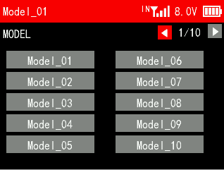
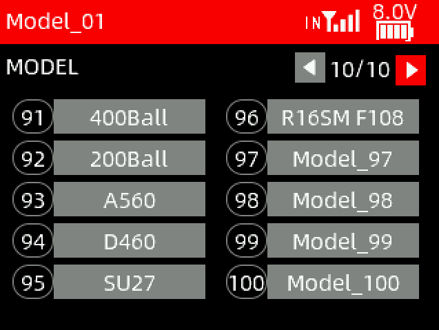 T16D can store up to 100 sets of model data, and you can select the model you want at any time.
T16D has added the custom models. Models 91-96 are the models from RadioLink, including 400 Ball, 200 Ball, A560, D460, SU27, and F108. These models provide you the default parameters of the models, which allows you to directly control the corresponding models.
4.1.2 Model Type
A total of eight different types of models are provided, including fixed-wing, delta wing, multi-rotor, helicopter, car, boat, tank and robot. Users can also select the model type under the advanced settings menu.
4.1.3 Model Copy/Paste
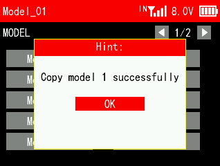
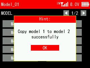
When a new model is the same or similar to a previously used model, you can use this function to copy it in order to quickly complete the settings.
For example, if you need to copy the data of model 1 to model 2, you can select model 1 and click copy, then select model 2 and click paste. Please note: When copying a new model, the name of the original model will also be copied. You need to distinguish and rename the new model to avoid confusion.
4.1.4 Model Rename
You can write and change the model name for the selected model.
4.1.5 Model Reset
Model reset is to clear all the settings of the current model and restores the current model to default values.
4.2 SYSTEM SETTING
SYSTEM SETTING menu is used to set language, sound, volume, idle alarm, vibration, vibration intensity, battery type, battery alarm, calibration voltage, brightness, backlight time and auto shutdown.
SYSTEM SETTING 1/3
LANGUAGE
The menu interface is available in multiple languages, including Chinese, English, German, French, Russian, Japanese, Spanish, Korean, Thai and Polish. The menu language of T16D is English by default, You can select any other language you want.
SOUND
Sound is to set the sound for system and alarm. You can select alarm only, key only, key plus alarm.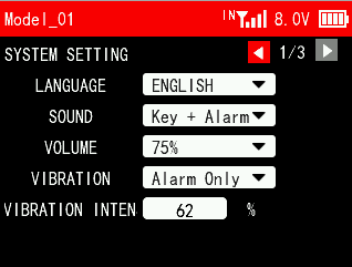
VOLUME
Volume is to set the volume of the sound. You can set it to 0%, 25%, 50%, 75% and 100%. 100% is the maximum volume.
VIBRATION
Vibration is to set the vibration of the system and alarm. You can select alarm only, key only, key plus alarm. NULL means there is no vibration.
VIBRATION INTENSITY
Vibration intensity is to set the vibration grade. You can set it from 0 to 100%.
SYSTEM SETTING 2/3
BATTERY TYPE
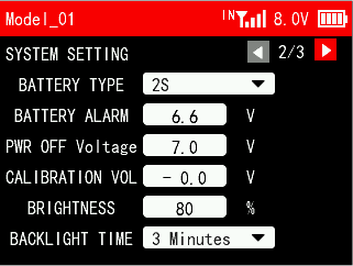 Set the battery type to accurately view the capacity of the battery icon in the upper right corner. If the wrong battery type is selected, the battery icon capacity in the upper right corner will display an error.
BATTERY ALARM
Battery alarm is to set alarm voltage for the battery of the transmitter. When the battery voltage is lower than the alarm voltage, an alarm will sound. Battery alarm defaults to 6.6V.
PWR OFF Voltage
When the voltage of the transmitter reaches the PWR OFF voltage, the transmitter will automatically shut down.
CALIBRATION VOLTAGE
When there is a difference between the battery voltage displayed and the actual battery voltage, you can set calibration voltage to make the voltage display consistent. The adjustment range is between -5V and +5V.
BRIGHTNESS
Brightness is to set the brightness of the screen.
BACKLIGHT TIME
Backlight time is to set the time of the backlight, namely how long the screen stays on when there is no operation. NULL means the screen won’t goes off when there is no operation for a long time. You can set at most 1 hour.
SYSTEM SETTING 3/3
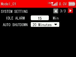 IDLE ALARM
Idle alarm is to set the alarm time when there is no operation on the transmitter. When the transmitter is on standby for a long time without operation, an idle alarm can be set to remind the user to avoid over-discharging of the battery caused by long-term standby. The idle time can be set from 0 to 360 minutes.
AUTO SHUTDOWN
AUTO shutdown is to set the time of auto shutdown, namely how long the transmitter will turn off automatically when there is no operation. NULL means transmitter won’t turn off automatically when there is no operation for a long time. You can set at most 1 hour.
4.3 STICK MODE
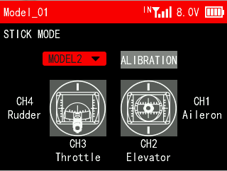 T16D provides five stick modes, including mode 1, mode 2, mode 3, mode 4 and custom mode. You can set it according to your habit. Mode2 is the default mode. Changing between modes 2/4 and modes 1/3 will need to modify the throttle stick.
Note: When selecting custom mode, users can change the control switches of channels 1 to 4 to switches other than joysticks (such as SWA/VRA, etc.). Before setting to custom mode, please make sure that the model is powered off to avoid safety accidents.
The tutorial of custom mode: https://www.youtube.com/watch?v=zaKR1PPKBFw
The tutorial on how to change T16D stick mode: https://www.youtube.com/watch?v=diCzEsvhSdk
T16D joystick calibration tutorial: https://www.youtube.com/watch?v=8txnY0JfuB8
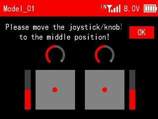
When there is any problem with the servo display of the transmitter or the servo value does not return to 0, you may need to calibrate the joystick of the transmitter. Here are the joystick calibration methods:
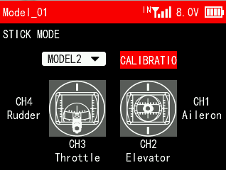
Move the cursor to CALIBRATION and press Push button to confirm it.
Move the two sticks and knobs to the middle position, and press Push button to confirm it.
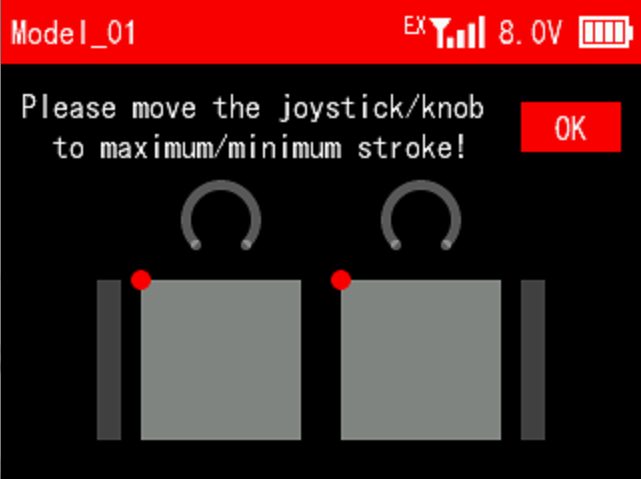
There is a prompt to move the joystick/knob to maximum/minimum stroke, and press Push button to confirm it.
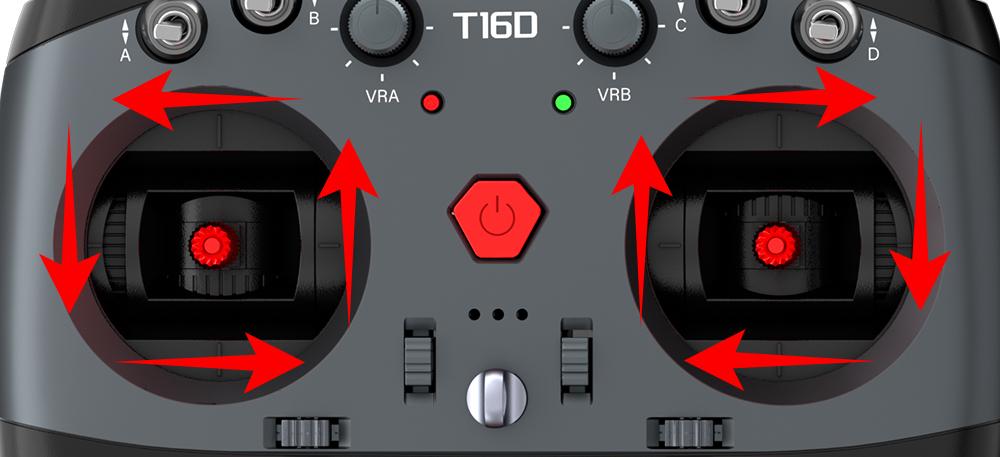
Push the two joysticks to the lower left corner, lower right corner, upper right corner, upper left corner respectively. Refer to the picture below:
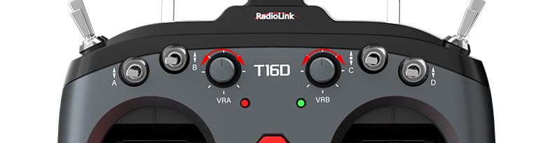
Turn the knob, VRA and VRB, clockwise to the maximum, and then counterclockwise to the minimum. Refer to the picture below:
Then press Push button to confirm it. The calibration is done.
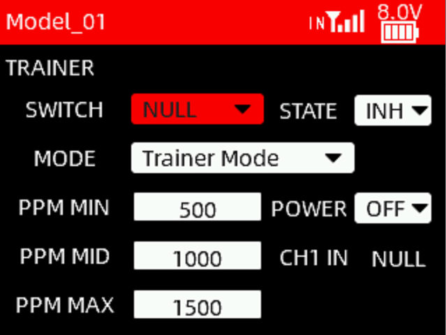
4.4 TRAINER
SWITCH: A switch can be used to turn on/off the PPM signal input and output. Optional switches include SWA, SWB, SWC, SWD, SWE, SWF, SWG and SWH. NULL means no switch assigned.
 STATE:
INH: This function is not enabled.
ON/OFF: Turn on/off this function.
MODE:
MIX IN: It is often used for head track input.
Trainer Mode: When T16D is used as a coach transmitter, set Trainer Mode to control the modelalternately with the student transmitter.
Student Mode: When T16D is used as a student transmitter, set Student Mode.
PWR: This option can be set when T16D works as a coach transmitter and RadioLink wireless trainer cable is used. ON means the Type-C port of T16D can supply power to the receiver bound to student transmitter. OFF means the Type-C port doesn’t supply power. (Note: Only trainer transmitter T16D with hardware V1.0.2 or above support RadioLink wireless trainer cable. Please enter MAIN MENU--Transmitter Settings--ABOUT to check the hardware version of the current transmitter.)
CH1 IN: When T16D works as a coach transmitter and the trainer function is turned on, it can automatically identify the PPM value of channel 1 of the student transmitter, which is used to check the PPM input value of the student transmitter. Push the joystick of channel 1 of the student transmitter, and the CH1 IN will change accordingly. Adjust PPM MIN/PPM MID/PPM MAX on the current interface based on CH1 IN to make T16D compatible with other head track or trainer devices.
PPM MIN/PPM MID/PPM MAX: To adjust the pulse width of PPM input and output. Due to the compatibility of different head track or trainer devices, when the PPM neutral point, maximum value, and minimum value cannot correspond, you can modify the PPM MIN/PPM MID/PPM MAX here.
Note: There are two methods to use the trainer function for T16D. One is to connect via trainer cable and the other is to connect via RadioLink wireless trainer cable. For detailed connection and setting methods, please refer to the link: https://www.radiolink.com/newsinfo/955662.html
4.5 TIMER
Timer display and control settings. T16D provides 2 timers, which can be set independently. The setting method is the same.
T16D timer function tutorial: https://www.youtube.com/watch?v=2f0sw2P0bXQ
TIMER 1/2
 TYPE: There are two modes available, including UP and DOWN. UP: The timing starts from 0. DOWN: The timer starts counting down from the set time.
ALARM: Alarm time. When the timing time reaches the time set here, the transmitter will start to sound an alarm. It defaults to 5 minutes.
ON/OFF: A switch can be used to start and stop timing. Optional switches include SWA, SWB, SWC, SWD, SWE, SWF, SWG , SWH and THR (throttle stick).
RESET: A switch can be used for timing reset. If the timing has already started, push the reset switch once and the timing will start again; If the timing stops, push the reset switch once and the timing will be reset.
Note: After the timer ends, you need to push the reset switch once to reset the timer before starting the next timer.
ALARM:
INH: When the timer ends, no alarm beeping.
ON: When the timer ends, the transmitter will sound a beeping alarm.
VIBRATION:
INH: When the timer ends, no vibration.
ON: When the timer ends, the transmitter will vibrate to prompt.
TIMER 2/2
Please refer to Timer 1.
4.6 SWITCHES SETTING
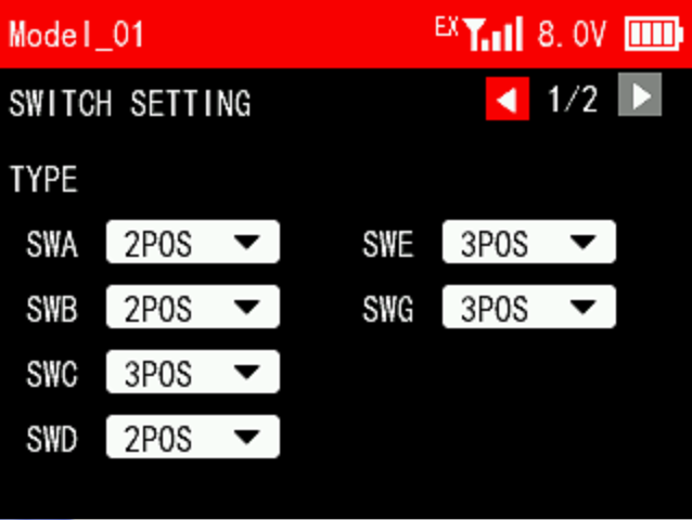 SWITCH SETTING 1/2
This function can set 2 position switches as 3 position switches, or the 3 position switches as 2 position switches. If the physical switch is replaced, this function can be used to set the corresponding switch type. You can set the switch types of SWA, SWB, SWC, SWD, SWE and SWG.
Note: Due to hardware reasons, SWF and SWH can only be used as 2 position switches and cannot be set as 3 position switches.
For example, when the 2 position switch SWD is set to 3 position switch, keep holding SWD in the middle position, it is the middle gear, SWD_MID; when the 3 position switch SWC is set to 2 position switch, the middle gear SWC_MID does not take effect.
T16D switch settings function tutorial: https://www.youtube.com/watch?v=rloVHAI-XiI
SWITCH SETTING 2/2
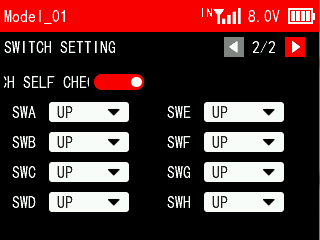 SELF CHECK: Used to turn on/off the switch self check. A white dot on the left indicates off, and the dot on the right indicates on.
The position of the switches can be set to UP/MIDDLE/DOWN.
If you need to put SWA, SWB, SWC, SWD, SWE, SWF, SWG and SWH in a specific position (such as UP/MIDDLE/DOWN) when the transmitter is turned on, you can turn on the switch self check, and the switch self check function is turned off by default.
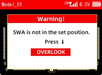
For example: Turn on the switch self check function and set SWA to DOWN here. When the transmitter is turned on next time, if SWA is not in the lowest position, the transmitter interface will prompt "SWA is not at the set position. Press ↓". Please push SWA to the lowest position, and the warning will be released.
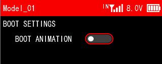
4.7 BOOT SETTINGS
This setting is used to turns on/off the startup animation.
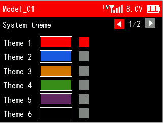
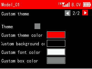
4.8 THEME SETTINGS
This function can be used to set the theme color, background color, font color and box color. All colors can be customized.
4.9 ABOUT
Users can view the RadioLink website, hardware version, software version and device name here.
Reset System Settings
All parameters in the "System Settings" menu except "Language" can be reset.
Click "Reset System Settings", the screen will prompt "Do you want to reset system settings?". Select "Yes" and the system settings are reset.
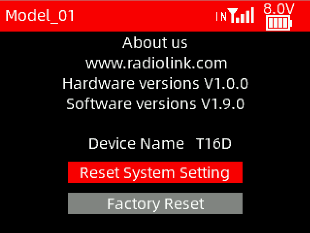
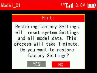
Factory Reset
All parameters of the transmitter can be reset, including system setting parameters and all model data.
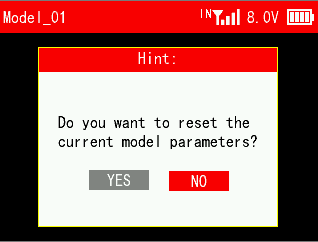
Note: If you just need to clear the current model parameters, please reset the current model in the MODEL menu in Transmitter Settings. Factory reset here will clear all model data. Once the model data is cleared, it cannot be restored, so please use this function with caution!
Click "Factory Reset" and a prompt will appear on the screen asking if you need to restore factory settings. Select "Yes" and wait for about a minute to reset all the settings.
Chapter 5 Receiver Settings

This chapter introduces all functions in the menu Receiver Settings, including RF SETTINGS, SUBSIDIARY ID, SENSOR, and FAILSAFE.
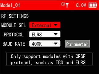
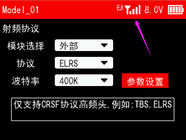
5.1 RF SETTINGS
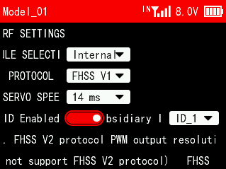
MODULE SELECTION: Internal and External can be selected.
When the transmitter is not connected to any external module, select internal in "Module Selection", and IN will be displayed next to the signal tower on the top taskbar.
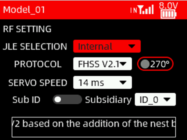
PROTOCOL: The protocol of the receiver. FHSS V1, FHSS V2 and FHSS V2.1 can be selected.
270°: 270-degree servo. This option can be enabled when the FHSS V2.1 protocol is selected and a 270-degree servo is used.
SERVO SPEED: Servo response speed. 14ms, 4ms, 3ms can be selected. 14ms is the response speed of the analog servo. 4ms and 3ms are the response speeds of the digital servo. If you are using a digital servo, you can select a servo speed of 4ms or 3ms. Please confirm whether the receiver you are using supports digital servo.
For the differences of the protocols and servo speed, please refer to the table below:
Protocol | PWM Output Resolution | Servo Output | Channel Number | Compatible Receiver |
FHSS V1 | 2048 | 14ms | 8 | All receivers compatible with T16D |
FHSS V2 | 4096 | 3ms/4ms/14ms available | 8 | R16F, R16SM, R12F, R8FGH, R8FG V2.1, R4FGM V2.1, and R8FG and R4FGM receivers with a factory date of 2023/4/26 or later |
FHSS V2.1 | 4096 | 3ms/4ms/14ms available | 16 | R16F, R16SM, R12F |
After switching protocols, please re-bind the receiver and the transmitter. | ||||
When the transmitter is connected to an external module, select external in "Module Selection". After selecting external, EX will be displayed next to the signal tower on the taskbar. At this time, setting parameters of the external module will appear on the current interface, such as PROTOCOL, BAUD and RATE.
Note: When External nodule is selected, RadioLink receivers cannot be bound to T16D.
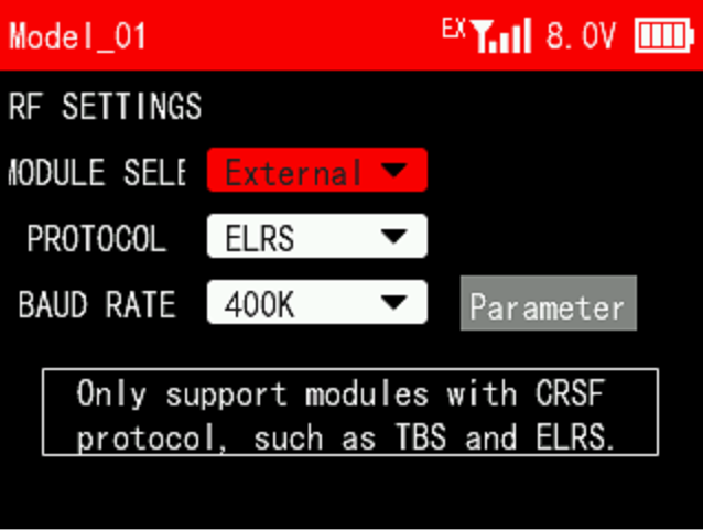
PROTOCOL: ELRS, CRSF V2 and BeastX are optional. Different protocols are selected when different modules are used.
BAUD RATE: 400K, 921K and 1.87M are optional. When the data rate is 50~250Hz, you can select 400K; when the data rate is 500Hz, select 921K; when the data rate is 1000Hz, select 1.87M.
 The methods on how to connect ELRS module to T16D and set them:
Tutorial: https://www.youtube.com/watch?v=64idhfqYJLA
Install the external module on T16D. Power on T16D and the receiver (The receiver can be connected to the TELEM port of the flight controller. Supply power to the flight controller to power on the receiver.).
Enter the menu -> Receiver Settings -> RF SETTINGS. Select MODULE SELECTION to External.
Set PROTOCOL and BAUD RATE based on the specifications of the module. (Please refer to the manual of the module for details). Then enter Parameter.
Wait for the transmitter to read the parameters of the module.

T16D is reading the parameters of the module.
(Note: If T16D is not connected to an external module or the connection fails, it will remain on the current interface. Long press the End button to exit.)
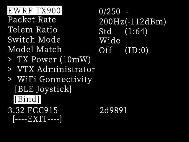
Parameters read successfully
(Note: When the module and receiver are not bound, a short line “-” will be displayed in the upper right corner)
Power off and power on the receiver for three times continuously to enter the binding mode (The LED of the receiver keeps flashing twice).
Select and press Bind on the current interface of the transmitter to start binding.
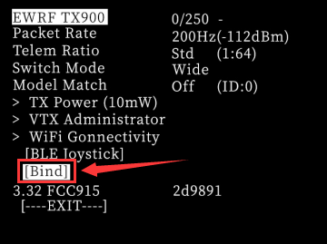
After the binding is successful, the short line “-” in the upper right corner will change to "C". Return and you can see the signal tower on the top, and the LED of the ELRS receiver is always on.

If the binding fails, please repeat steps 5 and 6.
5.2 SUBSIDIARY ID
T16D can bind with multiple receivers. When T16D and multiple receivers have been bound successfully, and T16D and all successfully paired devices are turned on at the same time. There are two ways to use them:
1. When Subsidary ID function is turned off, T16D can control multiple devices at the same time.
2. When Subsidary ID function is turned on, T16D can control the specified device according to the selected Subsidary ID. T16D has 16 groups of Subsidary ID functions, and each ID corresponds to a receiver. Set the Subsidary ID first. When all the devices are turned on, you can control one of the devices through the Subsidary ID function. At this time, the other devices are on standby.
For example: Bind T16D with a truck and a car and turn all them on. First, use T16D to control the car to run to the bucket of the truck, and then switch the receiver ID on the truck to drag the car back to the destination.
 Subsidary ID function setting steps:
Turn on Subsidary ID function. Then set the ID number according to your models and then finish the binding and parameters set for each receiver.
Once the Subsidary ID is turned on, the corresponding ID number will be displayed on the main interface of T16D.
Note: If you want to switch subsidiary ID number with a 2 position switch or 3 position switch, please refer to Chapter 3.3 CONDITION.
T16D Subsidiary ID function Tutorial: https://www.youtube.com/watch?v=_I68EFqkm7Q
5.3 SENSOR
The function is used to set alarms for RSSI, receiver voltage and external battery voltage, and the calibration for receiver voltage and external battery voltage.
SENSOR 1/2
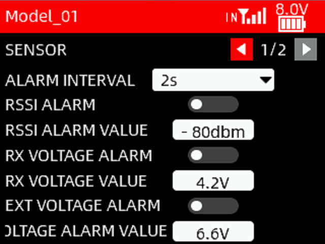 Alarm interval: When the RSSI value, receiver voltage and external battery voltage reach the alarm values respectively, the transmitter will issue an alarm prompt. The alarm interval can be set to 2s, 5s, and 10s.
RSSI ALARM: The alarm can be turned on/off. A white dot on the left indicates off, and the dot on the right indicates on.
RSSI ALARM VALUE: When the RSSI value of the receiver reaches the RSSI alarm value, the transmitter will issue an alarm. The maximum value can be set to -125dbm, and the default value is -80dbm. The specific alarm value can be set based on the control range you want.
RX VOLTAGE ALARM: The alarm can be turned on/off. A white dot on the left indicates off, and the dot on the right indicates on.
RX VOLTAGE VALUE: When the receiver voltage reaches the receiver voltage alarm value, the transmitter will issue an alarm. The minimum alarm value can be set to 3V. The maximum can be set to 12V. It defaults to 4.2V.
EXT VOLTAGE ALARM: The alarm can be turned on/off. A white dot on the left indicates off, and the dot on the right indicates on.
EXT BATTERY VOLTAGE ALARM VALUE: When the external battery voltage reaches the external battery voltage alarm value, the transmitter will issue an alarm. The minimum can be set to 3V. The maximum can be set to 60V. It defaults to 6.6V.
Note: If you need to use the alarm function, please make sure that the alarm sound or vibration is turned on in the system settings menu.
SENSOR 2/2
RX_V: Receiver Voltage. If it shows NULL, no receiver voltage has been received.
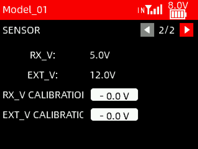 EXT_V: External battery voltage. If it shows NULL, no external battery voltage has been received.
RX_V Calibration: When there is a difference between the receiver voltage displayed and the actual receiver voltage, you can set calibration voltage to make the voltage display consistent. The adjustment range is between -5V and +5V.
EXT_V Calibration: When there is a difference between the external battery voltage displayed and the actual external battery voltage, you can set calibration voltage to make the voltage display consistent. The adjustment range is between -10V and +10V.
5.4 FAILSAFE
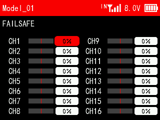 Fail safe is an important safety setting. When the signal is lost, it can be used to protect the model from loss or reduce the degree of loss. It can also play a certain protective role in personnel safety. This function sets the output value performed by each channel when the signal is lost. All channels default to 0% and can be customized according to the needs of the device.
Chapter 6 Firmware Update
T16D will keep updating the firmware to add new functions or optimize the current functions. Please pay attention to our website www.radiolink.com.cn to get the latest firmware.
T16D firmware update tutorial: https://www.youtube.com/watch?v=bJnml-aJZdU
Firmware update steps:
1)Download firmware
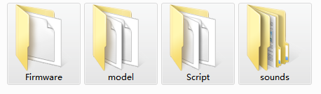
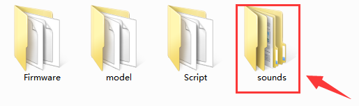
>Download the latest firmware from https://www.radiolink.com.cn/t16d_firmwares The firmware of T16D is a zip file. After downloading it to the computer, you need to unzip it first. The unzipped files contains 4 folders, including Firmware, model, Script, and sounds.
2)Prepare the transmitter
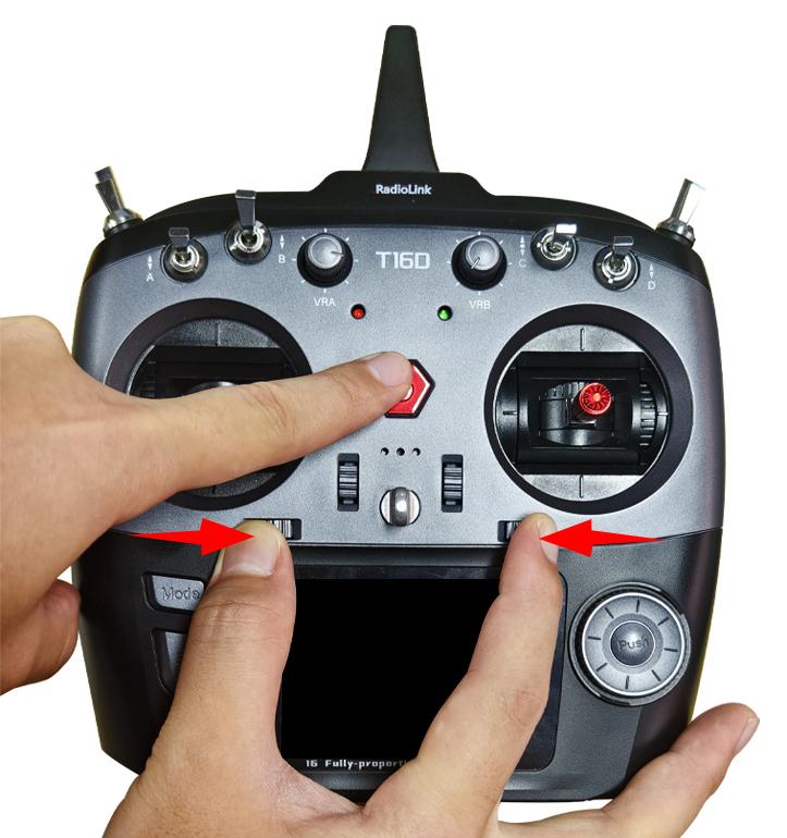
>Connect battery to T16D. Power off the transmitter.
>Push these two TRIM buttons to the middle, and long press the power button at the same time until you hear a D sound.
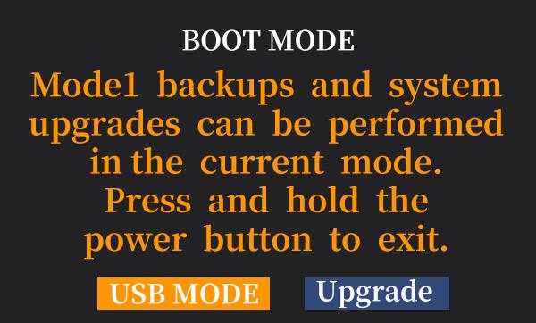
3)Enter USB mode
>The following BOOT MODE interface will appear on the screen of the transmitter. Select "USB MODE" and press the Push button to confirm.
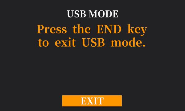
>The following USB MODE interface will appear on the screen, indicating that it has entered USB mode, and the computer will also remind you that a USB flash drive is inserted.
4)Copy the firmware
>The computer will display the removable disk of T16D. Open the disk.
>Copy the filesthat you have downloaded into T16D.

Note: If a file replacement prompt appears during the firmware copy process, please select "Yes" for all to replace the original folders.
5)Enter Upgrade mode
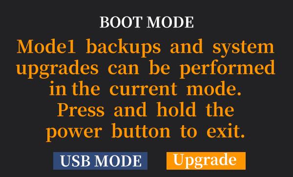
>After the firmware copy is complete, short press the End button to exit USB mode.
>The following BOOT MODE interface will appear on the screen. Select "Upgrade" and press the Push button to confirm.
6)Upgrade firmware
>The following Upgrade MODE interface will appear on the screen, indicating that it has entered upgrade mode. Select "YES" and press the Push button to confirm.
>The transmitter starts to upgrade the firmware, and the percentage of the interface indicates the progress of the firmware upgrade.


7)Firmware upgrade successful: When“Firmware upgrade successful”appears on the screen, the upgrade is successful.
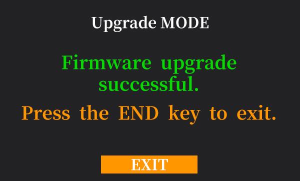
8)Exit upgrade mode
>Short press the End button to exit upgrade mode.
>Long press the power button to use the transmitter normally. You can check the current firmware version in Transmitter Settings--ABOUT menu interface to confirm that the firmware upgrade is successful.
Chapter 7 Customized switch voice production
T16D supports customized switch voice. Users can use text-to-speech software to create custom voice files, and then copy the voice files into the transmitter to use their own voice.
The tutorial on how to make customized switch voice on T16D:
https://www.youtube.com/watch?v=w-6v8xznyGc
The production method mainly includes the following three steps:
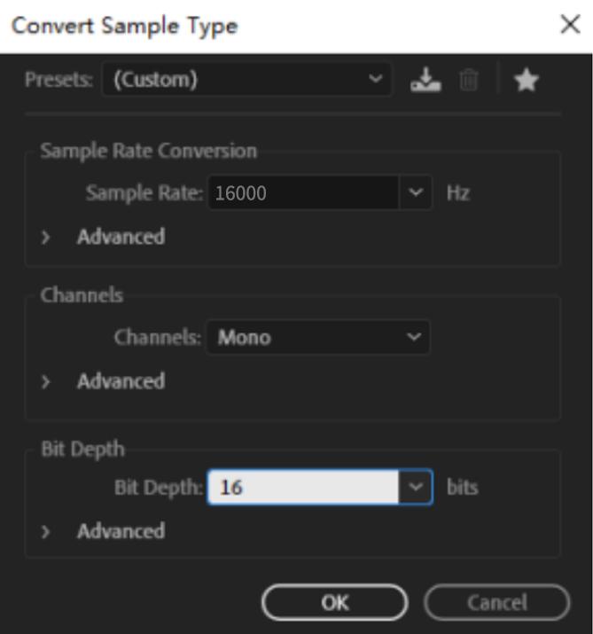
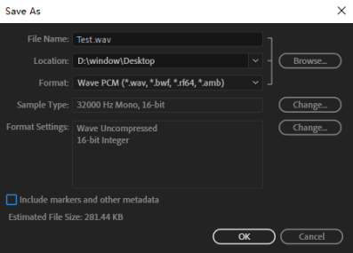
After recording the voice file, modify the format of the voice file to ensure that the format of the voice file meets the following four conditions:
WAV format
Sampling rate 16KHZ or 32KHZ
Mono
Bit depth 16 bits
The following pictures show how to convert the format of an audio file to make it meet the above 4 conditions. Take Adobe Audition voice software as an example: Import the voice file whose format needs to be modified into Adobe Audition software, and then click File - Save As.
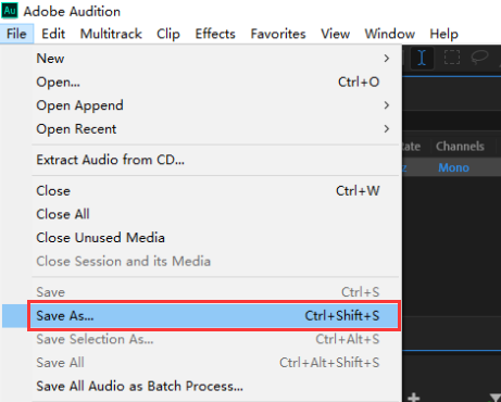
Modify the voice file format to ensure that the format conforms to WAV format, Sample rate 16KHZ or 32KHZ, monophonic, and 16 bits depth. After selecting the save location, click OK, and a qualified voice file will be generated.
Note: Don't tick "Include markers and other metadata".
2. Copy the voice file into T16D.
Enter USB mode
>Connect battery to T16D. Power off the transmitter.
>Push these two TRIM buttons to the middle, and long press the power button at the same time until you hear a D sound.
>The following BOOT MODE interface will appear on the screen of the transmitter. Select "USB MODE" and press Push button to confirm.
>The following USB MODE interface will appear on the screen, indicating that it has entered USB mode.
Copy the voice file
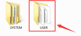
>The computer will display the removable disk of T16D. Open the disk. Copy the audio filesinto T16D-sounds-USER.(Take the audio file Landing gear open as an example)
Note: The audio copied into the transmitter needs to be named according to the user's needs, so that the user can select the corresponding voice file on the transmitter.
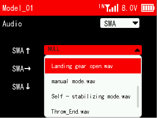 3. After the copy is completed, exit the USB mode. Power on T16D, and then you can select the audio file in SWITCH AUDIO menu.