
I. RC8X Remote Control System
1.1 Safety Precautions
1.1.1 Safety Guidelines for Transmitter
- Do not operate outdoors on rainy days, run through puddles of water, or use when visibility is limited. Should any type of moisture (water or snow) enter any component of the system, erratic operation and loss of control may occur.
- Do not operate in places that are near people or roads.
- This product is not a toy and is NOT suitable for children under the age of 14. Adults should keep the product out of the reach of children and exercise caution when operating this product in the presence of children.
- Always ensure the trim levers are at 0 and the battery is properly charged before connecting the receiver.
- Always check the throttle trigger on the transmitter to be sure it is in the neutral position before turning on the power switches of the transmitter and receiver. Always be sure the engine is not running or the motor is stopped before turning off the power switches.
- Make sure that you turn on the transmitter power switch and then turn on the receiver or speed control power switch when you are ready to operate the model. Make sure that you turn off the receiver or speed control power switch and then turn off the transmitter power switch when you are ready to stop operating the model. If the power switches are turned on or off in the opposite order, the model may unexpectedly run out of control and cause a very dangerous situation.
- Before running, check if the function moves the servos to the preset position. Trigger the throttle trigger and steer the steering wheel to check if the motor and servo move to the preset position. When adjusting the model, make sure the engine is not running. You may unexpectedly lose control and create a dangerous situation.
- Never power on the RC8X out of 7.0V-17V. 8 pieces AAA batteries, a 2S-4S LiPo battery, or a 6S Ni-MH battery are permitted.
- Never charge the RC8X with the USB port. The Type-C port on the left of RC8X is used to update firmware, copy data, supply power to the 5.8G image transmission module, and temporarily supply power to RC8X. It cannot be used to charge the battery of RC8X.
1.1.2 Safety Guidelines for SD Card
- Never unplug and plug the Micro SD card when the transmitter turns on, especially if the transmitter is reading the data, or it will damage the SD card or loss of data.
- An SD card needs to be inserted into the RC8X for normal use. Please make sure the SD card is inserted before use.
1.2 RC8X Introduction
1.2.1 Features
RC8X, is an 8 channels transmitter, with a 4.3 inches, full-color, backlight LCD touch screen, which runs smoothly like a smartphone.
It is packed with the R8FG receiver, with built-in gyro, and supports a high voltage servo, which is capable of RSSI (Received Signal Strength Indicator), receiver, and model battery voltage telemetry.
RC8X is capable of an arbitrary ID designation among a maximum of 16 binding receivers and can keep a maximum of 200 pieces of model parameters saved.
Setting Menu, font, desktop, system theme, etc., can be customized, and you can achieve a totally unique 8-channel transmitter without one code to modify.
Multiple Programmable Mix Control such as 4WS, 4WD, Tank mixing, Tilt mixing, CPS mixing, etc.
RC8X, with steering curve, throttle curve, brake curve, etc., is an ideal partner for all types of RC cars and boats in the market including single-engine and twin-engine models such as crawlers, tanks, caterpillars, short-course trucks, drifting cars, gasoline car, mini car, monster truck, off-road car, GP car, EP car and other types of cars or boats.
1.2.2 Specifications
RC8X Transmitter | |
Dimensions | L*W*H: 121*163*209mm (4.76"*6.42"*8.23") |
Weight | 438.5g(15.47oz) |
Model Types | Car (Including Crawlers/Tanks/Caterpillars etc.)/Boat/Robot |
Channels | 8 channels |
Screen | 4.3 inches, 800*480 full-color, backlit IPS touch screen |
Control Distance | 600 meters(1968.5ft) (Maximum range tested in unobstructed areas free of interference) |
Operating Current | 250mA±10mA@8.4V (the IPS screen light on) 190mA±10mA@8.4V (the IPS screen light off) |
Operating Voltage | 7~17V DC (8 pieces of AAA batteries or a 2S-4S LiPo battery or a 6S Ni-MH battery) |
Type-C Port Voltage & Current | Input Voltage: 5 V (RC8X can be powered by computer or mobile power bank via Type-C cable) Input Current: Maximum 500mA Output Voltage: 4.6V-5.0V Output Current: Maximum 1A |
DSC Port Voltage | Input Voltage: 0-5V Output Voltage: 0-3.3V |
Antenna | Built-in Antenna |
Frequencies Band | 2.4GHz ISM band (2400MHz-2483.5MHz) |
Modulation Mode | GFSK |
Transmission Power | <20dBm |
Spread Spectrum | FHSS, 67 channels pseudo random frequency hopping |
Channel Resolution | 4096 with regular jitter of 0.5us |
Response Latency | 3ms, 4ms, 14ms can be selected |
Menu Customized | Font, desktop, system theme, etc., can be customized |
Low Voltage Alarm | Low transmitter voltage, low receiver voltage, low model battery voltage or low RSSI alarm can be customized |
Dimension of Battery Case | L*W*H =92*52*14.5mm(3.62"*2.05"*0.57") |
Model Memory | 200 models |
Subsidiary ID | 16 |
Compatible Receiver | R8FG(Standard), R8FGH, R7FG, R6FG, R6F, R8EF, R8F, R8FM, R8SM, R8XM, R4F, R4FGM |
Voice Broadcast | Support |
CRSF Protocol | Support |
Compatible Control Board Hardware Models | Ardupilot, pix4, beta, Arduino, and Raspberry Pi, can be connected with SBUS signal |
Operating Temperature | -30° to 85° C |
R8FG Receiver | |
Dimensions | L*W*H =35*24*13.5mm (1.38"*0.94"*0.53") |
Weight | 10.5g (0.37oz) |
Antenna Length | 205mm (8.07”) |
Channel | 8 channels |
Control Distance | 600 meters (1968.5ft) (Maximum range tested in unobstructed areas free of interference) |
Operating Current | 35mA (5V) |
Operating Voltage | 3-12V |
Signal Output | SBUS&PWM |
Telemetry | Real-time built-in telemetry of model battery voltage, RSSI, and receiver voltage |
Water Splash Proof | The waterproof grade is IPX4 |
Gyro | Receiver with gyro integrated, customizable gyro sensitivity |
Response Latency | 3ms, 4ms, and 14ms can be selected when it is bound to RC8X, (R8FG is V2.1 or R8FG with a factory date of 2023/4/26 and later.) |
Compatible Transmitter | RC8X, RC6GS V3, RC4GS V3, RC6GS V2, RC4GS V2, RC6GS, RC4GS, T8FB, T8S |
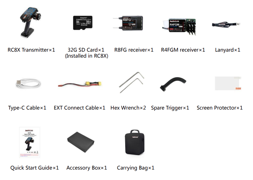
1.2.3 Package List
1.2.4 Buttons Introduction
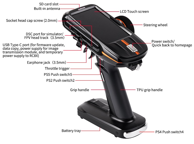
The USB Type-C port of RC8X is not only used to update firmware, copy data, and supply power to the 5.8G image transmission module but also used temporarily to supply power to RC8X. When the battery of RC8X is dead or the simulator is used, you can connect the power supply device such as a mobile power bank or a computer to the USB Type-C port to supply 5V power to RC8X, and then long press the home button to power on RC8X.
Note:
- When the USB Type-C port is used to supply power to RC8X, please make sure the battery in the battery tray is removed to avoid over-discharging.
- The maximum input voltage of the RC8X Type-C port is 5.5V.
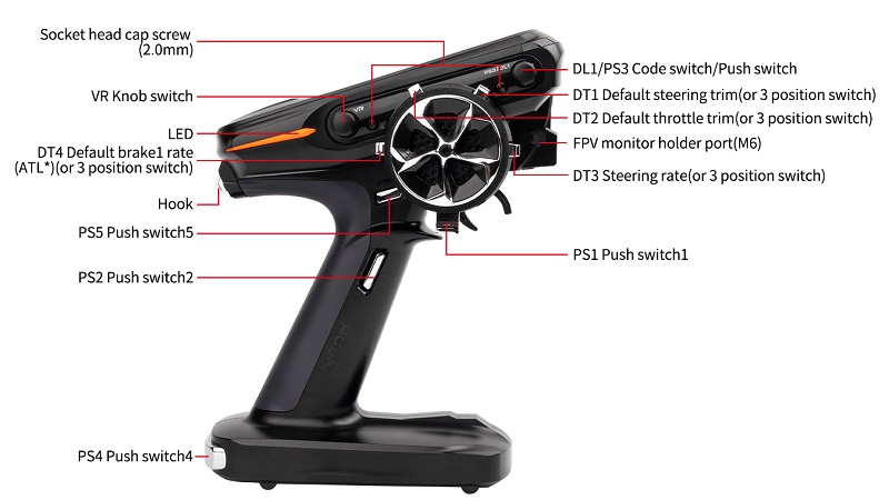
1.2.5 Nomenclature of Buttons
Switch/Knob | Full name | Function | Operation |
DT1 | Digital Trim 1 | default steering trim | Push the button forward or backward to adjust the value. Restore to factory settings by pushing the buttons. Four DT buttons can work as four 3 position switches by setting. Please refer to chapter 1.2.8 Three Position Switch. |
DT2 | Digital Trim 2 | default throttle trim | |
DT3 | Digital Trim 3 | Default dual rate | |
DT4 | Digital Trim 4 | Default brake1 rate (ATL*) | |
DL1/PS3 | Digital Dial 1 | Code switch, Gyro gain | Turn the dial counterclockwise /clockwise to adjust the value |
Push Switch 3 | Default press PS3 to turn on or turn off the backlight can be programmed | Press the switch to enable it | |
PS1 | Push Switch 1 | Default control CH4 can be programmed | lock switch or jog switch can be programmed. |
PS2 | Push Switch 2 | Default control CH5 can be programmed | Two PS2 switches on the left and right side, convenient for left and right-handed users |
PS4 | Push Switch 4 | Default control CH6 can be programmed | |
PS5 | Push Switch 5 | Default control CH7 can be programmed | Two PS5 switches on the left and right side, convenient for left and right-handed users |
VR | Knob switch | Dial, default control CH3, can be programmed | |
HOME | Power switch /Switch for quick back to the homepage | ||
SS | Steering switch | The steering switch controls channel 1 by default to turn the vehicle left and right. You can also assign it to control channel 1 and other functions at the same time. | |
TS | Trigger switch | The trigger switch controls channel 2 by default to make the vehicle move forward or backward. You can also assign it to control channel 2 and other functions at the same time. | |
1.2.6 Two Position Switch
PS1, PS2, PS3, PS4, PS5, Steering switch, and Trigger switch can be used as 2-position switches by setting. The setting method is as follows:
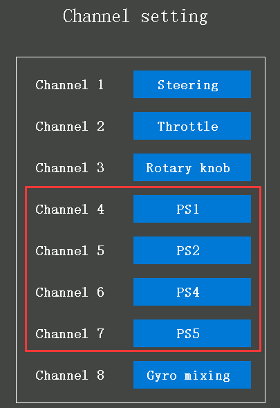
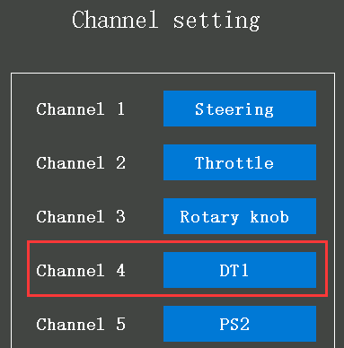
- Select any one of the PS1/PS2/PS3/PS4/PS5/Steering switch/Trigger switch for the channel to be set in the "Channel Setting" menu(The switches of channel 4 to channel 7 are PS1/ PS2/PS4 /PS5 by default, see picture below);
- Enter the "Switch select" menu, and set the "Type" of the corresponding switch to "lock", so that when you press the switch once, the channel output will jump from the initial value to the maximum value (or minimum value); press the switch again, the channel output will jump to the minimum value (or maximum value).
- After setting, the switch can be used as a 2-position switch. Return to the home page and press the corresponding switch to check the servo display.
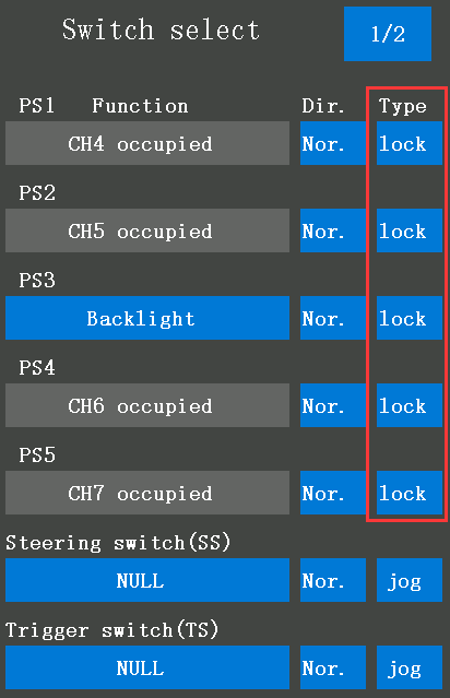
Note: If you set the "Type" of the switch to "jog", the value will reach the maximum (or the minimum) when pressing the switch, and back to the original value when loosen. For example: if the "Type" of PS1 is "jog", the servo value will reach +100 when pressing PS1 and will back to -100 when loosen. For more details on the switch setting, please refer to 2.2.7 Switch Select.
1.2.7 Three Position Switch
The four DT buttons can also be used as four 3-position switches by setting. The setting method is as follows.
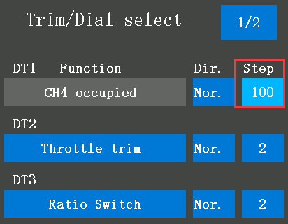
3 position switch setting tutorial:
- Select any DT button for the channel to be set in the "Channel Setting" menu (Take Channel 4, DT1 as an example);
- Enter the "Trim/Dial select" menu, and set the step of the corresponding DT button to 100, so that every time the DT button is toggled, the travel amount will go directly to 100. You can also set different values according to your needs.
- After setting, the DT button can be used as a 3-position switch. Return to the home page and toggle the corresponding DT button to check the servo display.
1.2.8 Preparation before Turn on Transmitter
1.2.8.1 Power for Transmitter
RC8X is easily adapted for various battery layouts with wide operating voltage of 7.2V to 17V, which can use 8 pieces of AAA batteries, a 6S Ni-MH battery or a 2S-4S LiPo battery. Universal JST connector with the voltage protection software of RadioLink ensures vital components are protected from a reverse polarity connection.
Attention: If the battery is accidentally connected reversely and a USB cable is used to supply power to RC8X at the same time, the transmitter will be damaged.
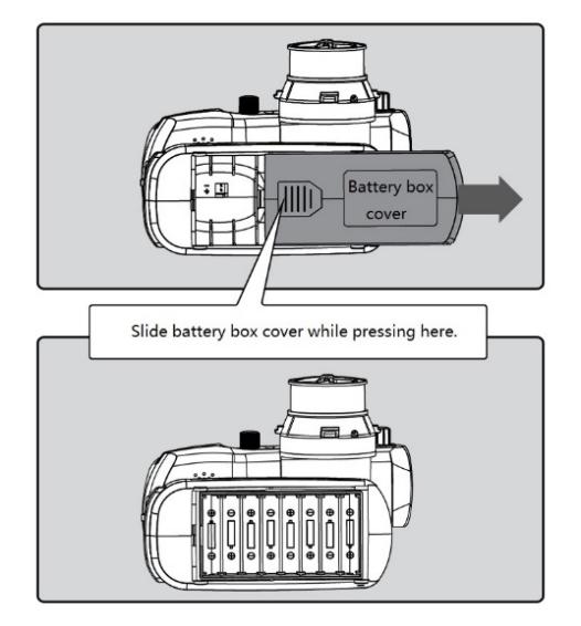
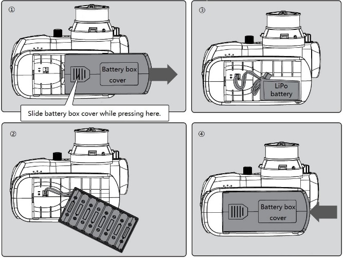
1) AAA Battery
① Remove the battery cover from the transmitter by sliding it in the direction of the arrow following the picture at right.
② Load 8 pieces of new AAA batteries. Pay attention to the polarity markings.
③ Make sure the 8 pieces' AAA batteries are not loose.
④ Slide the battery cover back onto the case.
2)LiPo Battery
① Remove the battery cover from the transmitter by sliding it in the direction of the arrow following the picture at right.
② Remove the battery box.
③ Plus LiPo batteries. Pay attention to the polarity markings.
④ Slide the battery cover back onto the case.
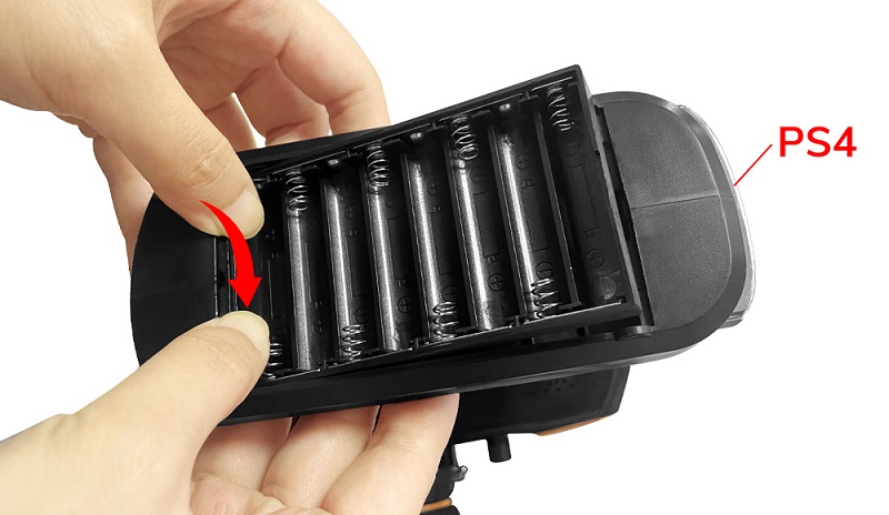
If you use a LiPo battery for power supply, you need to remove the battery box that comes with the RC8X. Please refer to the following two methods to remove the battery box:
Press down one end of the battery box with your thumbs, and the other end will automatically lift up, and then the battery box can be taken out.
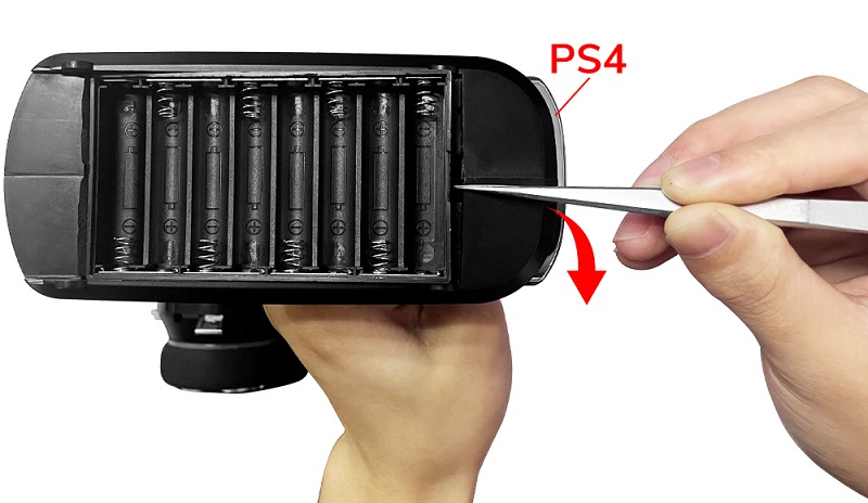
Use tweezers or other tools to pry one end of the battery box upwards to remove the battery box.
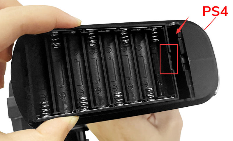
If you need to put the battery box back into the battery tray, please note that the notched end of the battery case faces the PS4 switch direction.
Attention:If your RC8X has plugged battery already, but still cannot turn on, please check below:
- Check if the AAA batteries have a reverse polarity connection.
- Check if the battery box has a reverse polarity connection.
- Check if the LiPo battery has a reverse polarity connection.
- Check if the AAA batteries have fully charged.
- If the input voltage is lower than 5V, the transmitter cannot be turned on.
1.2.8.2 Turn on the Transmitter
Long press the HOME button about 1.5 seconds, and the RC8X will show RadioLink Logo, and the welcome to RadioLink sound is emitted at the same time, the home page will display this information as in the picture below:
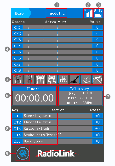
① The current model name. 200 models in total can be selected in the Model select menu. Make sure the model name on the display is consistent with the actual model before running. If the model name is not consistent with the actual model, the movement of the servo, the steering gear action, and the neutral position setting will be wrong, which may damage the car.
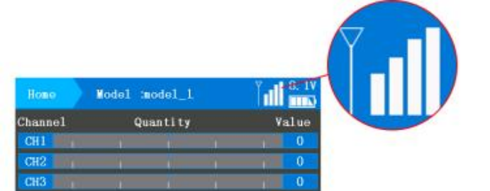
②  Receiver signal strength. The receiver signal strength will display on the top of the transmitter screen after the transmitter bind success with the receiver.
③ The battery voltage of the transmitter.
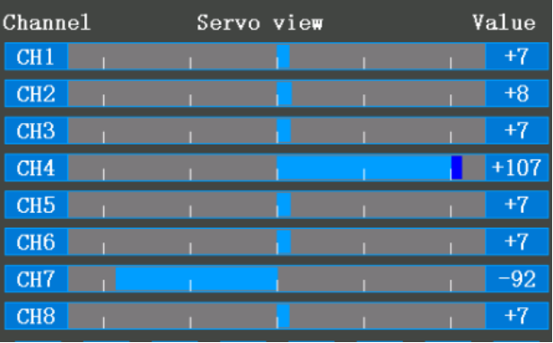
④ Servo operation from CH1 to CH8. Real-time bar-graph display to demonstrate exactly what commands the transmitter is sending to the servos.
⑤ Mixing function. The background color of the functional block will turn to blue if the mixing function corresponding turn on while the background color of the functional block will turn to grey if the mixing function corresponding turns off.
⑥ T1:Total timer. It is used to record the total uptime of the transmitter. Turning off the transmitter will not affect time accumulation.
T2:Click to time. Click the T2 timer functional block to start to time, stop to time or reset. Click once to start to time, click twice to stop time, and click thrice to reset. The timer set steps can follow: 2.6.2 Timer
⑦ Telemetry.
RX: the current input voltage of the receiver.
EXT: the current input voltage of cars or boats.
RSSI: the receiver signal strength, "NULL" indicates loss of signal or the transmitter and the receiver failed to bind. The RSSI is 0 to 30dBm is normal when the transmitter is about 60 centimeters from the receiver, the signal is better the RSSI data is closer to 0. The RSSI test steps can follow: 1.3.7 RSSI Testing
⑧ Button name and its function name, and state. The function and value represented by DT1/DT2/DT3/DT4/DL1 can be checked on the home page.
⑨ Into the setting menu. Into all the parameter setting menus by pressing this button.
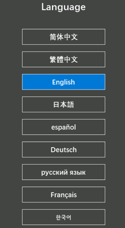
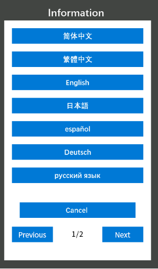
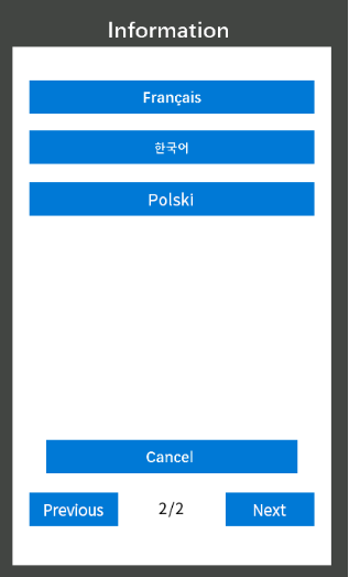
1.2.8.3 Language Select
The menu interface is available in multiple languages, including Simplified Chinese, Traditional Chinese, English, Japanese, Spanish, German, Russian, French, Korean, Polish and Spanish. The menu language of RC8X is English by default, language can be changed in Information Menu.
Turn on your RC8X, click the button  at the left bottom of RC8X into System menu , click the blue select box below the word Language, and then choose the language you want.
1.2.9 Icon Introduction
| Into setting menu |
| Model select menu | |
| System menu |
| SD Card Folder | |
| Basic menu |
| Back to the previous menu | |
| Telemetry setting |
| Increase the value | |
| Racing menu |
| Decrease the value | |
| Mixing setting |
| Reset the value | |
| Tools menu | |||


Click the above icon to enter the menu, and click each function under this menu to set it(check the manual catalog for functions under each menu).
Example: How to set "End point"?
Answer: Turn on the RC8X on the home page. Click  on the bottom left of RC8X into the System menu. Click
  into the Basic menu, and then click Endpoint in the menu to adjust the endpoint for channels 1 to 8. Click "-" to decrease the value, and click "+" to increase the value. Click Reset to restore the current value to the factory default value. After the setting is finished, click
  to return to the previous menu, or short-press the power button to return to the home page.
1.2.10 Transmitter Low Voltage Alarm
The transmitter's low battery voltage alarm is default to 6.8V. Suppose the voltage of the transmitter battery is lower than 6.8V. In that case, the transmitter will alarm with the sound "transmitter voltage low". Please change the battery when you hear the alarm, the value of the low transmitter battery voltage alarm can be set in the battery menu according to your battery that powered for your RC8X.
Setting steps: turn on your RC8X, click the button at the left bottom  of RC8X into the System menu, click
  at the left of RC8X into the Information menu, click Battery, click the blue select box at the right of Alarm voltage to change the alarm value, click "-" to reduce the number and click "+" to increase the number. If you use a 2S LiPo battery to power your RC8X, then the alarm voltage number does not lower than 7.4V (for 2S LiPo battery, 3.7V*2=7.4V), 3S LiPo battery does not lower than 11.1V, 4S LiPo battery does not lower than 14.8V.
Attention: the other parameter setting steps in the Battery menu can follow: 2.1.5 Battery (Transmitter Battery Voltage)
1.2.11 Compatible Receivers
RC8X is packed with an R8FG receiver by default. RC8X is also compatible with RadioLink R8FGH, R7FG, R6FG, R6F, R8EF, R8F, R8FM, R8SM, R8XM, R4F, R4FGM receivers.
Note: Since the RadioLink radio control system is not open-sourced, RadioLink transmitters are ONLY compatible with RadioLink receivers, and RadioLink receivers are ONLY compatible with RadioLink transmitters.
1.3 Receiver Introduction
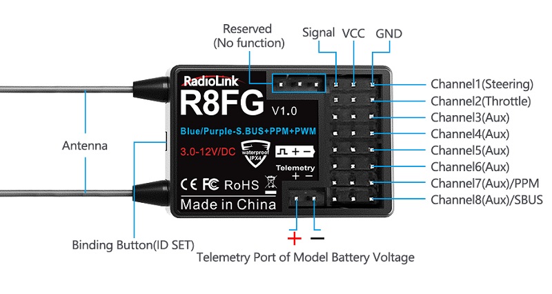
1.3.1 Features of R8FG
RC8X, packed with an R8FG, 2.4GHz 8 channels receiver, gyro integrated, and high voltage servo supported. FHSS spread spectrum algorithm and 67-channel pseudo-random frequency hopping make the R8FG get excellent anti-interference performance, perfect for multiplayer complete synchronously. R8FG also supports PWM, SBUS, and PPM signal output.
The gyro function (Green LED) of R8FG is turned off by default. If you want to turn on the gyro function, please follow the setting steps: 1.3.5 Gyro Function of R8FG
1.3.2 Binding
RC8X and R8FG have finished binding by default. Turn on the RC8X and the R8FG, the signal tower will show on the top of the screen as in the picture below, it means the transmitter and receiver have finished binding.
But if you buy a new receiver for your RC8X. Each receiver has an individual ID code and must bind with the transmitter before use. When the binding is done, the ID code will be stored in the transmitter and there's no need to rebind.
Binding steps:
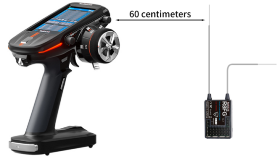
① Put the transmitter and the receiver close to each other (about 60 centimeters). Note: The close distance between the transmitter and receiver may cause a signal block, which leads to unsuccessful binding or signal loss.
② Turn on both the transmitter and the receiver, and then the LED of R8FG will start flashing slowly.
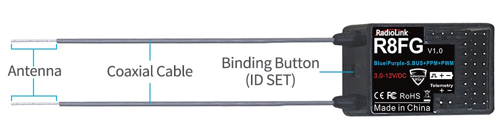
③ There is a black binding button (ID SET) on the side of the receiver. Press the button for more than 1 second and release, the LED will flash quickly, indicating the binding process is ongoing.
④ When the LED stops flashing and is always on, binding is complete and there will be a signal tower shown on top of the LCD screen of the transmitter(As shown above). If not successful, the LED will keep flashing slowly to notify, and repeat the above steps.
RC8X binding tutorial:
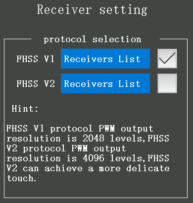
Note: If the receiver you are using is not R8FG, but other receivers such as R7FG, R6FG, etc., please select "FHSS V1" in the "Basic Menu" - "Receiver setting" of RC8X (as shown on the right), and then bind them. Click "Receiver List" here to check whether the receiver belongs to FHSS V1 or FHSS V2. If the communication protocol of the receiver is selected incorrectly, the binding will fail.
1.3.3 Receiver Connection
1.3.3.1 Connect Cable
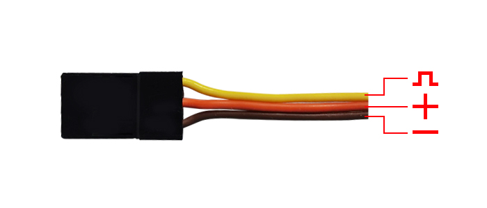
Picture 1
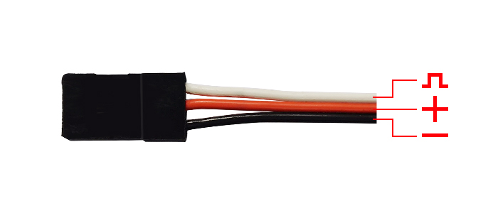
Picture 2
The connection wire for the receiver is shown in the picture above. The common ones are white/red/black wire (Picture 1) or yellow/red/brown wire (Picture 2). The two types of servo cables both are light-colored wire as the signal wire, dark-colored wire as the ground wire, and the middle is 5V power supply, and the three wires correspond to "  ".
".
Note: RadioLink receivers are all designed with anti-polarity connect protection. When the receiver is powered by a separate battery, the receiver will not be damaged if the battery polarity is reversed, but if the servo is connected at this time, it will damage the servo.
Note: Please do the following safety check before operating your model:
1. RSSI test (Received Signal Strength Indicator). For the test method, please refer to the manual Chapter 1.3.7 RSSI Testing.
2. Antenna inspection: The gray line on R8FG is coaxial cable, while the transparent line with a length of about 4-5 centimeters at the top is the antenna. If the transparent line is broken or damaged, it will directly affect the control distance. If any abnormality is found, please replace the receiver antenna in time.
1.3.3.2 How to Connect R8FG Correctly for Telemetry
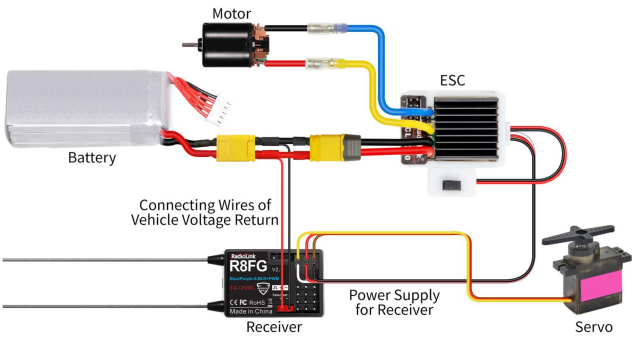
R8FG supports telemetry of the model battery voltage, receiver voltage, and RSSI. The model voltage will display by connecting the wire to the ESC, battery, and Telemetry port of receiver R8FG. Telemetry of maximum 8S battery(33.6V) supported. Model battery voltage telemetry can be easily achieved by connecting the male end of the battery wire to ESC while the female end to the battery and the wire with a JST head connects the Telemetry (+-) of R8FG as the below picture shows. No extra module is needed. Once connect with success, the returned model voltage will be displayed on the interface of returned flight information. The connection is shown below.
Attention:
- The reverse polarity protection circuit design for all 8 channels of R8FG ensures vital components are protected from a reverse polarity connection. But, the JST connector which is packed with R8FG for connecting to the battery cannot reverse polarity connect, or it will lead to the wrong voltage value telemetry.
- The telemetry port is only used to model voltage telemetry. It can not be used to power the receiver.
1.3.3.3 Low Model Voltage Alarm Setting
The low model battery voltage alarm is default 6.6V, if the voltage of the model battery is lower than 6.6V, the transmitter will alarm with the sound "low engine battery voltage", please replace the battery when you heard the alarm, the value of low engine battery voltage alarm can be set in the Telemetry menu according to your battery that powered for your model.

Setting steps: turn on your RC8X, click the button  at the bottom left of RC8X into the System menu, click
  into the Telemetry menu, click Sensor settings, click the blue select box named EXT voltage to change the alarm value, click "-" to reduce the number, and click "+" to increase the number. If you use a 3S LiPo battery to power your model, then the alarm voltage number does not lower than 11.1V (for 3S LiPo battery, 3.7V*3=11.1V), 4S LiPo battery does not lower than 14.8V.
Reset: Click Reset will make the alarm voltage number back to 6.6V.
Back: click the button  or short-press the power button to return to the previous menu.
Current: it defaults to 0, if the RC8X bind to receiver success, and connects the telemetry cable to the model battery, the real-time model voltage will shown here.
Alarm type: the sound type for the alarm, defaults without any warning tone. But if you want the RC8X waning you have to change the battery when the model battery voltage is lower than the value you have set, there are voice broadcasts and 20 types of warning tones can be chosen.
Vibration type: it defaults "Inhibit", Mode1, Mode2, and Mode3 can be selected.
Alarm voltage: the low-model battery voltage alarm, defaults to 6.6V, the minimum voltage can be set to 6V, and the maximum voltage can be set to 60V, the low model battery voltage has set depending on the battery you use. Click "-" to reduce the number and click "+" to increase the number. If you use a 3S LiPo battery to power your model, then the alarm voltage number does not lower than 11.1V (for a 3S LiPo battery, 3.7V*3=11.1V), 4S LiPo battery does not lower than 14.8V.
Alarm interval: the interval period for the alarm, if the model battery voltage is lower than the alarm voltage you have set, it defaults to alarm once every 10 seconds, the alarm interval time can be customized.
1.3.4 Working Mode of R8FG
R8FG has a built-in gyroscope, which can output not only PWM signals but also PPM and SBUS signals. There are four working modes, including ordinary PWM mode, SBUS mode, Gyro mode, and Gyro + SBUS mode. The channel signal corresponding to each mode is as follows:
R8FG Working Mode | ||||||
Working Mode | PWM Mode | SBUS Mode | Gyro mode | Gyro + SBUS Mode | Note | |
Channel | Telemetry | Telemetry Port of Model Battery Voltage(+ -) TELEMETRY port is only for 2S-8S battery voltage telemetry. The port cannot be used to power the receiver. | ||||
1 | PWM | PWM | PWM | PWM | Steering | |
2 | PWM | PWM | PWM | PWM | Throttle | |
3 | PWM | PWM | PWM | PWM | Aux | |
4 | PWM | PWM | PWM | PWM | Aux | |
5 | PWM | PWM | PWM | PWM | Aux | |
6 | PWM | PWM | PWM | PWM | Aux | |
7/PPM | PWM | PPM | PWM | PPM | Aux | |
8/S.BUS | PWM | S.BUS | PWM | S.BUS | Aux | |
Working mode settings
Turn on/off the gyro: Short press the binding button 3 times within 2 seconds to switch the gyro on and off, and the color of the LED indicator will switch accordingly.
Gyro phase switch: Short press the binding button twice within 2 seconds to switch the gyro phase.
Turning on/off the SBUS: short press the binding button once to turn on/off the SBUS, and the color of the LED indicator will switch accordingly. After the SBUS signal is enabled, channels 1-6 output PWM; channel 7 outputs the PPM signal, and channel 8 outputs the SBUS signal.
R8FG working modes tutorial:
1.3.5 Gyro Function of R8FG
R8FG has a built-in gyroscope. The integrated high-performance gyro adopts the software filter and PID algorithm, timely and precisely corrects the sensitivity and improves the stability. Its good flexibility to different models and fields easily achieves professional performance even with drift cars.
Enable Gyro
The gyro function of R8FG is turned off by default. Since the integrated gyro in R8FG will self-check, it is very important to remain R8FG still when powering it on. When the red LED off means NO gyro.
Press the binding button three times (intervals of less than 1 second), the red LED will flash three times, indicating that gyro is enabled.
Attention:
It's normal that the servo keeps shaking when connect to the receiver, but the transmitter has not operated. Because the gyro will help to correct the steering gear angle of the servo automatically if the gyro function has turned on, you can turn off the gyro function if you do not need this function.
If the receiver has not to be moved, but the servo keeps shaking, there are two reasons below:
① the servo has connected to the PPM/S.B channel of the receiver, please reconnect the servo to the CH1/2/3/4/5/6, because the standard servo only supports PWM signal input.
② the gyro is too much sensitivity, please reduce the value of gyro sensitivity by turning the DL1 knob switch.
Gyro Reverse
Set the gyro forward, and turn the car right or left to see whether the gyro functions. The wheel will turn left when the car is turned right and the wheel turns right when the car is turned left. If the gyro acts counter, press the binding button twice, the red LED flashes twice, the gyro reverse is corrected.
Gyro Sensitivity Setup
Gyro sensitivity is defaulted to adjust by channel eight that default controlled by DL1/PS3 knob switch, turning the DL1/PS3 knob switch clockwise to increase sensitivity and anti-clockwise to reduce it.
When turning the DL1/PS3 knob switch, a tooltip with a yellow background color will pop out at the top of the screen, and the value of the channel will be changing at the same time, the value is closer to +100, the higher sensitivity. If the value is 0, it means the gyro function has been turned off.
If you want set DL1/PS3 to control other functions, you can set another switch such as PS1 as the Gain switch setting in the "Channel setting" menu.
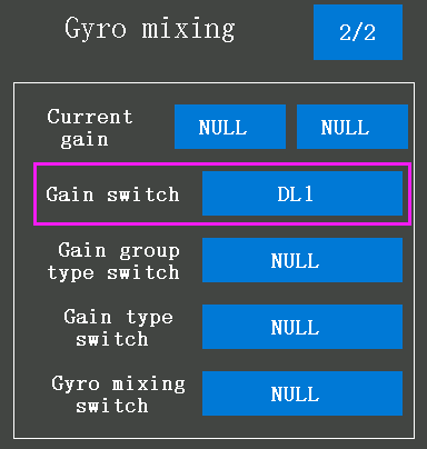
Setting steps: turn on the RC8X on the home page, click the button  at the left bottom of RC8X into the System menu, click
  into the Mixing menu, and click the blue select box named Gyro mixing. Click 1/2 at the top right corner and then Gain switch to assign a switch to control gyro sensitivity.
1.3.6 Installment of Receiver Antenna
It is important to install the receiver antenna correctly on the model, because wrong receiver antenna installation will cause poor signal quality.
How receiver antenna installation affects signal quality? Here are the common mistakes when installing the antennas:
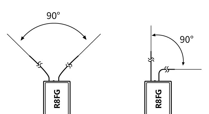
The two antennas of the receiver CANNOT overlap, because they will interfere with each other. Keep the two antennas at a 90-degree angles. (As shown below)
Antennas should NOT be placed near metal objects, because reflection of the conductor panel will drastically worsen the signal.
Do NOT keep antennas parallel to the ground. It should be placed vertically to the ground.
Big models may contain metal parts that influence signal emission. In this case. antennas should be positioned at both sides of the model to ensure the best signal status in all circumstances.
Antennas should be kept away from metal conductor and carbon fiber at least half inch away and no over bending.
Keep antennas away from motor, ESC or other possible interference sources.
Sponge or foam material is advised to use to prevent vibration when installing receiver.
Receiver contains some electronic components of high-precision. Be careful to avoid strong vibration and high temperature.
Special vibration-proof material for R/C like foam or rubber cloth is used to pack to protect receiver. Keeping the receiver in a well-sealed plastic bag can avoid humidity and dust, which would possibly make the receiver out of control.
Please refer to the below link for more details on how to install antennas of the receiver:
https://www.radiolink.com.cn/receiver_antenna_installation
1.3.7 RSSI Testing
If the control distance of cars or boats is short, please refer to this instruction to test the transmitter. This instruction will introduce the test procedure of the transmitter RSSI value and the solution to the abnormal RSSI value.

① Turn on the transmitter and power on the receiver at the same time, and then the transmitter and receiver will be connected (if not connected, you need to bind again), the signal tower appears on the transmitter interface, indicating that the binding is successful. The value of RSSI will appears on the Telemetry tooltip, and the RSSI value will keep changing according to the distance between the transmitter and the receiver. (As shown on the right)
② Make the receiver antenna and transmitter antenna parallel, keep the transmitter apart from the receiver about 60 centimeters, and both antennas straight. It is normal that the RSSI value is within the range of 0 to -30dBm. The closer the value is to 0, the stronger the signal is. (As shown below)
Here is the tutorial to show how to test RSSI:
Abnormal signal strength solution:
Check whether the antennas of the receiver and transmitter are damaged. Most signal strength degradation is caused by antenna damage. If it is damaged, the antenna needs to be replaced. If there is no damage, you can test the transmitter and receiver for malfunctions by replacing the receiver. If you still cannot solve the problem, email after_service@radiolink.com.cn to get support.
II. RC8X Basic Functions
2.1 System menu
In the System menu, users can set the language, system theme, backlight, sound, battery, vibration, LED brightness, home button, external input output, calibration, and information.
2.1.1 Language
The menu interface is available in multiple languages. The latest firmware of RC8X supports Simplified Chinese, Traditional Chinese, English, Japanese, Spanish, German, Russian, French, Korean and Polish. The menu language of RC8X is English by default.
2.1.2 Theme setting
In the system theme setting menu, the color of the theme, background, and font can be customized.
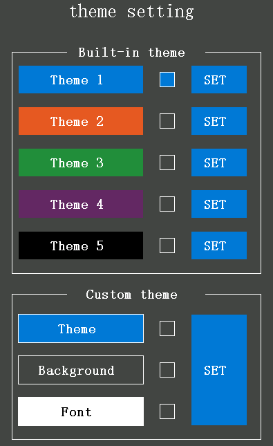
Built-in theme: the built-in theme refers to the theme that has the background and border colors preset. There are five built-in themes in total. Tap the SET button to quickly select the background and border color.
Custom theme: In the custom theme menu, RC8X users can set the theme, background, and font color by themselves.
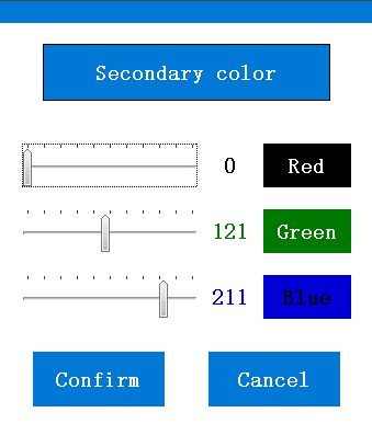
The custom colors of the theme, background, and font are composed of red, green, and blue. For example, if the values of the three colors of the theme are 0, the current border color is black.
Model interaction: Set ON to turn on model interaction, OFF to turn off model interaction. It defaults to OFF. When model interaction is turned on, different themes can be set for different models, and the themes will switch with the models. When model interaction is turned off, all models use the same current theme.
Setting steps: click Theme, Background, or Font that belongs to the Custom theme menu in the System theme setting menu to set your favorite color. Drag the scale plate to select the color. After confirming the color of Theme, Background, and Font, click SET to change the color to the secondary color you have selected. Click the SET button at the right of Theme1 to Theme5 to reset the settings in one second.
2.1.3 Backlight
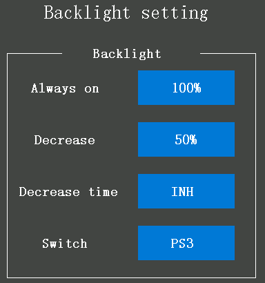
Switch: User can set a switch to turn on or turn off the backlight, PS1, PS2, PS3, PS4, PS5, Steering, Trigger can be select as the switch. Turn off the backlight when you have finished the parameters setting can save battery power.
Always on: The brightness value when the screen keep solid on. The maximum value of brightness is defaults 100%, tap the value button to change the brightness.
Decrease: The brightness automatically changes to this value when the transmitter stops operating for the"Decrease time".
Decrease time: The backlight decrease time function is default inoperative. Users can set a countdown to automatically change the "Brightness (Decrease)" when the transmitter stops operating for a certain period of time.
2.1.4 Sound
Voice mode:
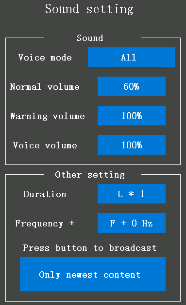
Silence: turn off all the sounds of the voice mode and select silence.
Alarm only: only broadcast the warning notes that have preset. When the current value same as or smaller than the preset alarm value, the RC8X will broadcast the warning notes. For example, you have set the transmitter will alarm with a sound when the receiver signal is -85dBm if the current signal is or is less than -85dBm, the transmitter will broadcast a "low receiver signal" to warn.
Without key tone: No voice when pressing the switches or tapping the screen. The other prompt tones work normally.
All: all the prompt tones are working.
Normal volume: This function can set the volume of all the prompt tones such as "operation", "warning" etc. The volume defaults to 30%. The minimum volume is 0% which indicates the sound function is off, and the maximum volume is 100%.
Warning volume: The sound when all the switches or buttons are pressed and the alarm sound from the system. The volume of the warning sound defaults to 100%, and it can be adjusted.
Voice volume: This function can set the volume of voice broadcast. The volume defaults to 100%, and the minimum volume is 20%.
Duration: Refers to the duration of a single prompt tone. L*1 indicates the shortest duration and L*4 indicates the longest duration
Frequency+: Refers to the softness of the prompt tone. The minimum frequency is default F+0Hz and the maximum is F+200. The lower the value, the softer the sound, and the higher the value, the sharper the sound.
Press the button to broadcast:
All the content: When the user triggers the functions that have preset with voice broadcast consecutively or simultaneously, the transmitter will broadcast all the operations in turn. No matter how many operations you have done, the broadcast will start after you have finished the first operation.
The 1st & last operate content: Only broadcast the first operation and the last operation if the operations are consecutive. But, if the operation starts during the second broadcast, it will broadcast the first, the second, and the last operation.
Only the newest content: only the latest operation will be broadcasted. The speech will be interrupted by the newly triggered content and then the transmitter will go to broadcast the latest content.
2.1.5 Battery (Transmitter Battery Voltage)
Voltage 1/2
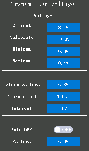
Current: the real-time transmitter battery voltage will display here when the transmitter is powered by a battery.
Calibrate: to make the voltage of the battery consistent with the voltage displayed by increasing or decreasing the calibration voltage value.
Minimum: The lowest operating voltage is the default 6.0V. The transmitter will stop working if the battery voltage is lower than 6.0V. The minimum operating voltage can be adjusted according to the battery. It can be adjusted from 5V to 17V. If the battery is a 2S LiPo, then the minimum operating voltage is suggested not to be lower than 3.7V*2S=7.4V, and 3S LiPo batteries should not be lower than 11.1V.
Maximum: The highest operating voltage is default 8.4V. It can be adjusted from 5V to 17V.
Alarm voltage: The low transmitter battery voltage alarm is default 6.8V. The transmitter will broadcast with "transmitter voltage low" when the transmitter battery voltage is lower than the alarm voltage, please change the battery when you have heard the alarm.
Alarm sound: The transmitter will alarm with a voice or a sound effect if the transmitter battery voltage is lower than the alarm voltage you have set. The alarm sound can be adjusted.
"NULL" indicates without any sound if the transmitter battery voltage is lower than the alarm voltage you have set.
"Sound" indicates the transmitter will broadcast with voice or other 20 types of sound effects if the transmitter battery voltage is lower than the alarm voltage you have set.
"Warning1-20" indicates the warning type. Twenty types can be selected.
Interval: The interval period for the alarm is by default 10 seconds. If the transmitter battery voltage is lower than the alarm voltage you have set, the transmitter will alarm once every 10 seconds. The interval period can be adjusted from 10 seconds to 3600 seconds.
Auto OFF: "ON" indicates the Auto OFF is working. If it is set to "ON", the transmitter will turn off automatically when the transmitter battery voltage is lower than the turn-off voltage you have set.
Voltage: If the transmitter battery voltage reaches the voltage you have set here, and the Auto OFF button is ON, the transmitter will turn off automatically. The auto-off voltage is the default 6.6V. It can be adjusted from 5V to 17V.
Attention: Please set the auto-off voltage according to your battery. The auto-off voltage set too high will lead to the battery not being used effectively, while too low will lead to your battery being over-discharged.
No operation 2/2
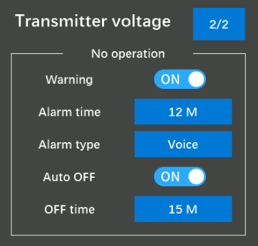
Warning: When RC8X is on standby for a long time without operation, the warning sound can be set to alert the user to avoid over-discharging of the battery caused by long-term standby. Set ON to turn on the warning, OFF to turn off the warning.
Alarm time: The alarm time when there is no operation on the transmitter. M means minute. The shortest is 1 minute, and it defaults to 12 minutes, which means that when the transmitter is idle for 12 minutes, the alarm will sound.
Alarm type: Voice or buzzer can be selected. When Voice is selected, when the no-operation alarm time is reached, the transmitter will alarm with a voice "Equipment is idle for too long".
Auto OFF: "ON" indicates the Auto OFF is working. If it is set to "ON", the transmitter will turn off automatically when it is idle for the below“OFF”time. "OFF" means that the automatic shutdown function is not enabled.
OFF time: When the idle time of the transmitter reaches the“OFF time”, and the Auto OFF is set to ON, the transmitter will automatically shut down. The shortest is 3 minutes, and it defaults to 15 minutes.
2.1.6 Vibration setting
Vibration by touch: The word is ON, and the select box's background color is blue, indicating the vibration function is turned on. The word is OFF, and the select box's background color is grey, indicating the vibration function is turned off. The vibration function is turned off. If the vibration by touch function is turned on, the transmitter will vibrate accompanied by the sound you have preset when you tap the screen and warn.
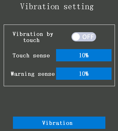
Touch sense: The touch sense is default 20%, it can be adjusted from 10% to 100%. Users can hardly feel the vibration if they set the value of touch sense to 10%, the larger the value, the stronger the vibration. Click "-" can decrease the value and click "+" can increase the value.
Warning sense: The warning sense is default 20%, it can be adjusted from 10% to 100%. Users can hardly feel the vibration if they set the value of warning sense to 10%, the larger the value, the stronger the vibration. Click "-" can decrease the value and click "+" can increase the value.
2.1.7 LED setting
LED refers to the LED strips on the left and right sides of the transmitter.
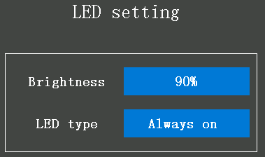
Brightness: If the LED type is selected as "Always On", the brightness of the LED strips on the left and right sides of the transmitter can be adjusted. Its default is 90%, which can be adjusted from 0% to 100%. The larger the value, the brighter the light. This setting does not affect the " breathe and backlight brightness" mode.
LED type: there are three types to select, which are "Always on", "Breathe", and "Backlight".
"Always on": The LED strips will always keep on according to the brightness you have set.
"Breathe": The LED strips will brighten and dim automatically on a regular basis.
"Backlight": The LED strips will follow the brightness setting of the screen backlight. If the backlight is turned on, the LED strips will turn on automatically.
2.1.8 HOME button setting
Push: Short pressing the home button can make it a shortcut key to switch between the current setting page and the main interface of the transmitter.

Long press: Press the home button for about 1.5 seconds to turn on or turn off the transmitter.
2.1.9 External input output
External input output 1/2
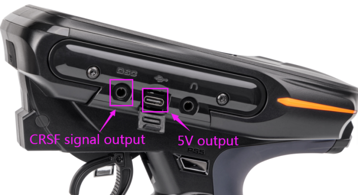
This function is mainly for the DSC multi-protocol port (the signal output mode setting when using equipment such as simulator, trainer cable, head track, Crossfire, 5.8G image transmission, and so on ), USB port, multimedia port working mode selection of RC8X.
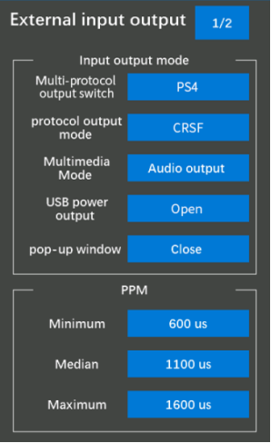
Multi-protocol output switch: You can assign a switch to turn on/off the multi-protocol output. You can set PS1, PS2, PS3, PS4 and PS5 to control it. NULL means no switch to control it.
Multi-protocol output mode: mainly for the signal type required by the device connected to the DSC port of the transmitter.
PPM_IN: When the DSC port is connected to the goggles FPV with head tracking function, select this signal mode; RC8X supports both 2 axis and 3 axis head track
Tutorial on how to connect DJI goggles to RC8X:
Here are some notices when using head track function on RC8X:
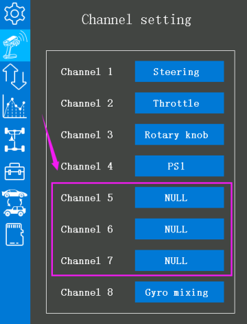
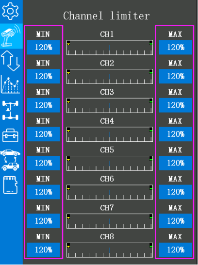
1. Generally, you need to set "NULL" in "Channel setting" for the head track channels. For example, if the head track device is connected to channel 5, channel 6, and channel 7, you can set "NULL" for channel 5, channel 6, and channel 7 (see picture below).
2. Because of the compatibility of different head track devices, there may be trim value added for each channel after successful connection of the goggles(see picture below):
Please adjust the below PPM value in "External input output" to meet the requirements of compatibility.
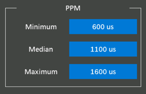
Please adjust the median value first to make the trim near 0.
Then please adjust the minimum to make the largest travel near -100%.
And finally adjust the maximum to make the largest travel near +100%.
If the largest travel of this channel exceed +100%, you can set the MAX value in Channel limiter to 100%.
PPM_OUT: When the DSC port is connected to the simulator or trainer cable, select this signal mode;
SBUS: When the DSC port is connected to a device that needs to be controlled by the SBUS signal, select this signal mode;
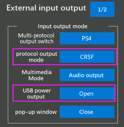
CRSF: When the DSC port is connected to TBS Crossfire/ELRS module, select this signal mode.
Tutorial on how to connect TBS Crossfire to RC8X:
Here are the steps to connect ELRS module to RC8X:
1. First set the protocol output mode in "External input output" to "CRSF";
2. Then set "USB power output" to "Open"
3. Connect the signal line of ELRS to the DSC port of RC8X;
4. Supply power to the ELRS module.
Note:
1. If you want to use the Type-C port (5V output) of RC8X to power the ELRS module, you need to purchase a 5V boost module separately to power the ELRS module.
2. If you use RC8X to supply power to the ELRS module, in order not to affect the normal work of RC8X, please do not continue to use RC8X to supply power to the ELRS module when the voltage of RC8X is lower than 7V.
Multimedia Mode: Mainly for the working mode setting of the headphone jack of RC8X.
Audio output: select this mode when headphones are plugged into the headphone jack.
Video input: select this mode when the headphone jack is inserted into a 5.8G video transmission module or other AV analog video signal equipment.
Tutorial on FPV setup:
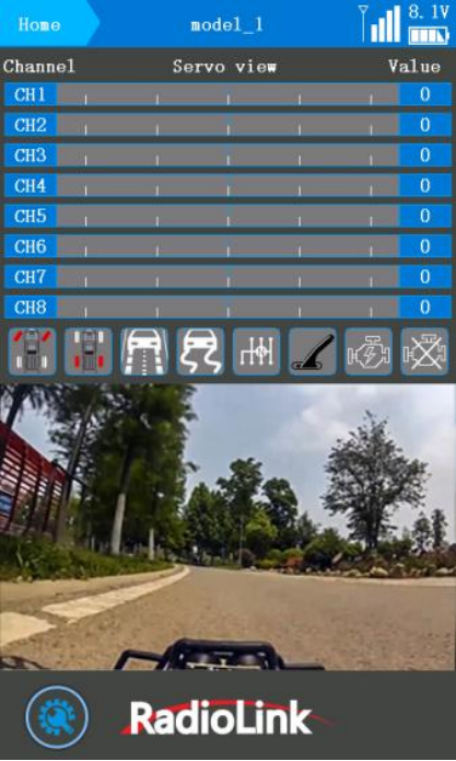
Note: When the cable of 5.8G image transmission module is successfully inserted into the headphone jack and the USB port, and the image transmission module has been successfully paired with the camera of 5.8G image transmission module, the RC8X screen will automatically split the screen up and down. The upper screen is the menu interface of the transmitter, and the lower screen is the shooting screen of the FPV camera. One screen is dual-purpose and does not interfere with each other. For details, see the picture on the right.
USB power output: The default is automatic, when the USB port of the transmitter is used to connect USB data cable to upgrade firmware or copy data to the transmitter, it is the normal USB mode. When the headphone jack is inserted into the 5.8G image transmission receiver, the USB port will turn on the 5V output, which can supply power to the 5.8G image transmission module.
pop-up window: When the headphone jack is connected to headphones and other devices, a pop-up window will pop up on the screen of the transmitter, multi-protocol mode selection (PPM, etc.) or multimedia mode selection (audio output or video input), click and select according to actual needs.
PPM: Pulse width adjustment of PPM signal input and output.
External input output 2/2
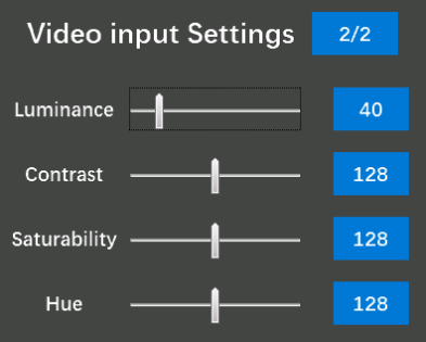
Video input settings: When RC8X is connected to the image transmission module, the parameters of the video displayed on the screen can be adjusted.
Luminance: Luminance of the video.
Contrast: Contrast of the video.
Saturability: Saturability of the video.
Hue: Hue of the video.
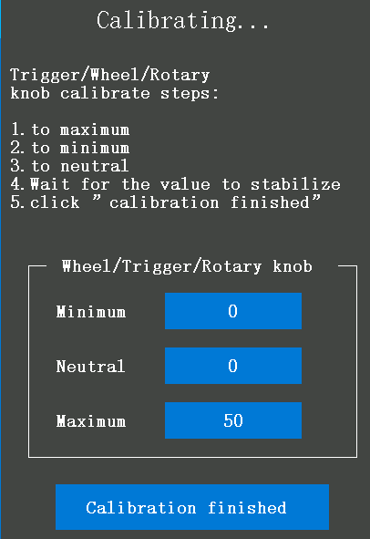
2.1.10 Calibration
Wheel, trigger, and Rotary knob corrections can be applied when a mechanical offset has occurred for some reason.
RC8X calibration tutorial:
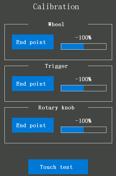
Wheel: Steering adjustment
Tap "End point" of the Wheel into the steering calibration menu, turn the steering wheel of the transmitter clockwise to the end, and then counterclockwise to the end (As shown on the right), then let it back to neutral automatically, wait until the minimum/neutral/maximum values are stopped to change, and then click "Calibration finished", then the transmitter will automatically return to the "Calibration menu" which means the steering calibration success.
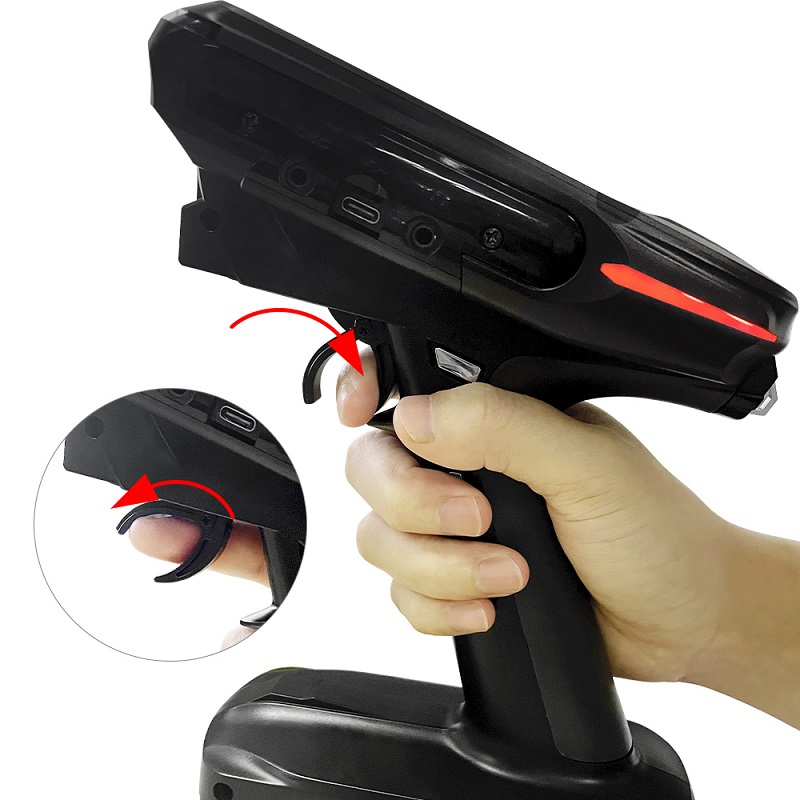
Trigger: Throttle adjustment
Tap "End point" of the Trigger into the throttle calibration menu, pull the throttle trigger to full throttle and the brake position (As shown on the right), then let it go back to neutral automatically, wait until the minimum/neutral/maximum values are stopped to change, and then click "Calibration finished", then the transmitter will automatically return to the "Calibration menu" which means the throttle calibration success.
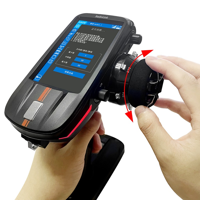
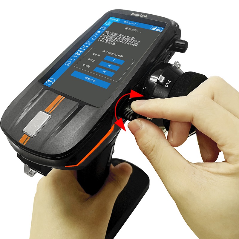
Rotary knob: VR button adjustment
Tap "End point" of the Rotary knob into the VR button calibration menu, turn the Rotary knob clockwise to the end, and then counterclockwise to the end, then rotate it to the neutral position (As shown on the right), wait until the minimum/neutral/maximum values are stopped to change, and then click "Calibration finished", then the transmitter will automatically return to the "Calibration menu" which means the Rotary knob calibration success.
Check if calibrate success: Clockwise and counterclockwise steering wheel or rotary knob to the end to check if the servo value can reach -100% and +100%, pull the throttle trigger to full throttle and the brake position the check if the value can reach to -100% and +100%. If it reaches, the calibration is successful, and if it does not reach -100% and +100%, it indicates a failure, please recalibrate.
Touch test: This function can detect whether the touch screen of the transmitter is abnormal. For example, if you find that you cannot click anywhere on the screen during use, you can enter the touch test interface and slowly slide your fingertips to the unclickable area. If the red dot cannot follow your finger, it means the touch screen is abnormal. If the test can't click or the insensitive place can normally appears red dot, it means the weather may be dry, please keep your fingers wet. When the test is completed, please click "Click here to exit the test" in the middle of the screen to return to the calibration menu interface.
Attention: The number changed during the calibration is the mechanical quantity of the corresponding switch, so each transmitter is slightly different, please ignore it.
2.1.11 Information
User name
The user name is default RADIOLINK and can be modified. After clicking the button "RADIOLINK" a keyboard will pop out, click "Delete" to delete the original name, tap "←" or "→" to move the cursor, and select the character of the model name you want to set or change, click "Confirm" at the bottom of the screen to save the setting.
Language
The menu interface is available in multiple languages. The latest firmware supportsSimplified Chinese, Traditional Chinese, English, Japanese, Spanish, German, Russian, French,Korean, Polish and Spanish. The menu language of RC8X is English by default. For how to selectlanguage you want, please refer to 1.2.8.3 Language Select
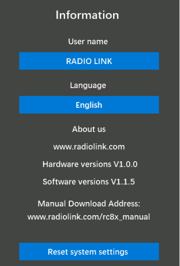
Reset system settings
The reset system settings function will make all the system settings (except “Language” and “calibrate”) return to the factory settings.
Click the button "Reset system settings", and click "Confirm" when the question "Are you sure to reset system settings?" will pop out. Click Confirm to reset system settings.
2.2 Basic menu
2.2.1 Channel reverse
This function reverses the direction of operation of the servos related to the transmitter's steering, throttle, channel 3, 4, 5, 6, 7, and 8 operations. CH1 to CH8 are default set as N.

Attention: "R" indicates REVERSE, and "N" indicates Normal.
If the channel has selected reverse, check the control of the corresponding channel on the model to confirm whether the response direction of the device connected to the channel is correct or not.
Attention: After the receiver is connected to the ESC, please calibrate the ESC and the transmitter according to the ESC manual, and then operate the throttle trigger, if there is no response, please set Channel 2 from "N" to "R" and then operate the throttle trigger to check whether the throttle channel device responds.
2.2.2 Channel Delay
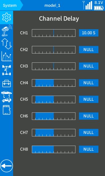
The function is to set delay for all the 8 channels, and the delay of each channel can be set independently.
The default value is "NULL", which means no delay. Users can click + button at the bottom of the screen to set the delay time. The channel delay can be set up to 10 seconds.
Note: When the throttle delay or steering delay function is turned on, the channel delay function will be disabled.
2.2.3 End point (EPA)
The function is to adjust the maximum travel of each channel. The left and right sides of each channel can be adjusted independently, the default value is 100, and 0 to 120 can be selected.
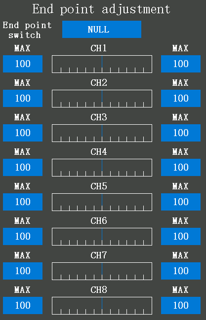
End point switch: Switch button used to switch the end point. you can assign PS1, PS2, PS3, PS4, PS5, steering switch (SS), trigger switch (TS), DT1, DT2, DT3, DT4, and DL1 to control it. "NULL" means to directly execute the current end point, with no switch to control it.
Tutorial of EPA:
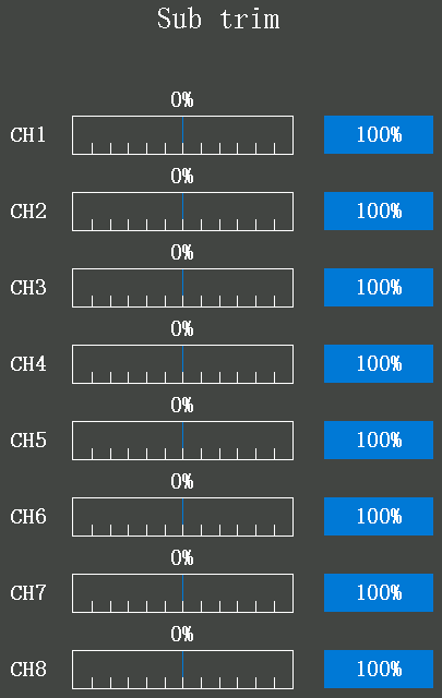
2.2.4 Sub trim
The function is used to correct mechanical errors, and adjust the neutral position of channel 1 to channel 8. The sub-trim of each channel is default 0%. -200% to 200% can be selected.
2.2.5 Channel setting
Channel 1 to channel 8 can be customized. All eight channels can be set and controlled by Steering, Throttle, Rotary knob, DT1, DT2, DT3, DT4, DL1, PS1, PS2, PS3, PS4, PS5, Steering switch, Trigger switch.
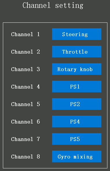
Channel 1: It defaults to control the steering wheel. Steering, Throttle, Rotary knob, DT1, DT2, DT3, DT4, DL1, PS1, PS2, PS3, PS4, PS5, Steering switch, and Trigger switch can be set to control the channel1.
Channel 2: It defaults to control the throttle trigger. Steering, Throttle, Rotary knob, DT1, DT2, DT3, DT4, DL1, PS1, PS2, PS3, PS4, PS5, Steering switch, and Trigger switch can be set to control the channel2.
Channel 3: It defaults to control by the Rotary knob. Steering, Throttle, Rotary knob, DT1, DT2, DT3, DT4, DL1, PS1, PS2, PS3, PS4, PS5, Steering switch, and Trigger switch can be set to control channel 3.
Channel 4-7: it defaults to control by PS1/PS2/PS4/PS5, the same setting as channel 3.
Channel 8: it defaults controlled by PS3, to adjust the Gyro mixing (Gyro sensitivity), turning the PS3 knob switch clockwise to increase sensitivity and anti-clockwise to reduce. When turning the PS3 knob switch, a tooltip with yellow background color will pop out at the top of the screen, and the value of the channel will be changing at the same time, the value is closer to +100, the higher sensitivity. If the value is 0, it means the gyro function has been turned off.
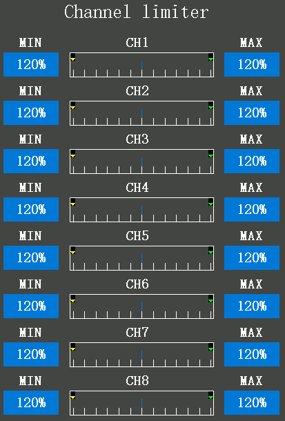
2.2.6 Channel limiter
The channel limiter function is to limit the minimum and the maximum servo movement. The initial value is 120%. 0% to 120% can be selected.
2.2.7 Trim/Dial select
Trim/Dial function select: This function is used to assign functions for the transmitter's digital trimmer button DT1, DT2, DT3, DT4, and dial button DL1. Click 1/2 at the top right corner to switch the setting menu.
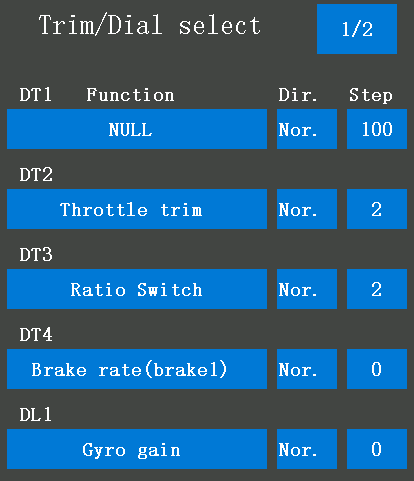
Button: DT1/DT2/DT3/DT4: the four digital trimmer buttons on the left side of the wheel. For details of all the buttons, please refer to 1.2.5 Buttons Introduction.
Dir.: the direction for the four digital trimmer buttons and the dial button, normal and reverse can be selected. If you select Nor., the value will increase when pressing clockwise the digital trimmer buttons DT1, DT2, DT3, and DT4 or rotate clockwise the dial button DL1. If you select Rev., the value will decrease when pressing anticlockwise the digital trimmer buttons DT1, DT2, DT3, and DT4 or rotating anticlockwise the dial button DL1.
Step: indicates the interval of the number change every time the button is pressed. For example, set the Step value to 6, and then each time the DT1 button is pressed, the value will increase or decrease by 6. The value of Step is default 2.
Return: DT1, DT2, DT3, and DT4 can be set with return function and used as momentary switches. If you check the trim button, it will automatically return to center. Return function is often used when the DT button is used as a three-position switch.
Function 1: DT1/DT2/DT3/DT4/DL1 can be set to control one of the functions as below: Steering trim, throttle trim, rotary knob trim, flap, dual rate, sub trim channel1/2/3/4/5/6/7/8, acceleration forward/brake1/ brake2/ brake3, steering curve, throttle curve, steering delay turn/return, steering delay turn(high/middle/low), steering delay return(high/middle/low), ABS (return brake1/2/3), ABS (delay brake1/2/3), ABS (cycle brake1/2/3), traction control (return /delay/cycle), brake1/2/3 rate, brake EXP(brake1/2/3), brake delay(brake1/2/3), tilt mixing(RUD to FLP), tilt mixing(FLP to RUD), idle up, programmable mixing1/2/3/4/5/6/7/8 A/B, 4WS front rate, 4WS rear rate, dual ESC, dual ESC ratio, gyro gain, Ackermann, condition.
Function 2: The four DT buttons can also be used as four 3-position switches by setting. For details of the setting, please refer to chapter 1.2.8 Three Position Switch.
"NULL": indicate that the function is not enabled.
Note: After assigning functions to each trim in this menu, if the trim button is selected again when setting other functions, the following prompt "Do you want to replace it?" will appear. If you want the trim button to control the original function, please click "NO"; if you want the trim button to control the new function, please click "YES".
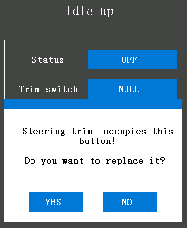
The above picture is taken as an example. DT1 initially controls the steering trim by default. If DT1 is selected again when setting the Idle up function, the above prompt "Do you want to replace it?" will appear. If you click "YES", DT1 will control the Idle up and no longer control the steering trim; if you click "NO", DT1 will still control the steering trim, but not the Idle up function.
Trim/Dial sound select:
Click 1/2 at the top right corner to switch to the settings menu. The sound of buttons DT1/DT2/DT3/DT4/DL1 can be set in this menu.
DTxA: the sound set for pushing the button forward.
DTxB: the sound set for pushing the button back.
Auto: indicates the sound type of the default factory setting.
NONE: indicate without any sound when pressing the button; eight types of beeps can be selected.
Audition: ON means that the audition will be played automatically after selecting the sound, and OFF means that the audition will not be played after the sound is selected.
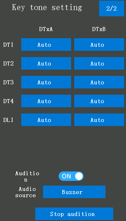
Audio source: indicate the type of sound, "Buzzer", "Warning voice", "System voice "and, "Customized voice" can be selected.
Beep1-8: buzzer type, eight types can be selected.
Warning 1-20: warning type, twenty types can be selected.
System voice: There are 55 kinds of function voice prompts by default. When the function of the button is set to be the same as the voice function here, you can rotate the corresponding voice broadcast prompt here. For example: After the DT1 trim key is used to control the four-wheel steering, you can select "4wd double" here, and the transmitter will broadcast the voice after selecting it.
Customized voice: Users can make custom prompt voice production through text-to-speech software, and then copy the voice file to the transmitter, where they can choose their own voice. For detailed information on how to make their own voice, please refer to 2.12 Customized Voice Production.
Stop audition: The button at the bottom of the screen is OFF, and the background color of the select box is grey, indicating that when selecting the buzzer or warning voice, the transmitter will broadcast the prompt tone that you have selected. The button at the bottom of the screen is ON, and the background color of the select box is blue, indicating that when selecting the buzzer or warning voice, the transmitter will not broadcast the prompt tone that you have selected. This stop audition function only applies to the Key tone-setting menu.
2.2.8 Switch select
Switch select
This function is for function settings of all the PS buttons, steering wheel, and throttle trigger.
Click 1/2 at the top right corner to switch the setting menu. For details of all the buttons, please refer to 1.2.5 Buttons Introduction.
Function: PS1, PS2, PS3, PS4, PS5, Steering switch, and Trigger switch can be customized to control the functions as below: Condition1/2, Condition1, Condition2, Condition3, Condition4, Program. Mixing1/2/3/4/5/6/7/8, A.B.S(brake1/2/3), Traction control, 4WS type switching, 4WS type1(front), 4WS type2(reverse), 4WS type3(same), 4WS type4(rear), Dual ESC (front/4WD/rear), Gyro mixing, Gyro gain, Gyro gain group, CPS mixing1/2/3/4, Brake, Start, Engine cut, Idle up, Neutral brake, Timer start, Timer reset, Screen capture, Backlight, Telemetry speech, Stop speech. If you select "NULL", it means will not trigger any function except the default function when pressing this button.
PS1: The button under the steering wheel, which defaults control CH4, can be customized.
PS2: The two buttons on the left and right sides of the handle, which default control CH5, can be customized. The two PS2 buttons have the same functions that are convenient for both left-handed and right-handed users.
PS3: The rotary knob in front of the steering wheel, the press button PS3 is integrated with the rotary knob DL1. If set this button as PS3, pressing this button will trigger the function that you have set, but rotating this button will not. If set this button as DL1, rotating this button will trigger the function that you have set, but pressing this button will not. PS3 defaults control the backlight of the transmitter, press once to turn off the backlight and press again to turn on the backlight, which can be customized.
PS4: The button located at the base of the transmitter, which defaults control CH6, can be customized.
PS5: The two buttons on the top left and right sides of the handle, which defaults control CH7, can be customized. The two PS5 buttons have the same functions that are convenient for both left-handed and right-handed users.
Steering switch (SS): It defaults control CH1, the rotating of the steering wheel, which can be customized to turn on or turn off other functions when rotating the wheel.
Trigger switch (TS): It defaults to control CH2, the forward/brake/back of the throttle, which can be customized to turn on or turn off other functions when triggering the throttle.
Attention: (SS) indicates the Steering Switch
(TS) indicates the Throttle Switch
For the position of the switches on the transmitter, please refer to 1.2.5 Buttons Introduction
Dir.: Indicate the direction of the buttons, normal and the reverse can be selected. Tap the blue select box to set "Nor." or "Rev.", the corresponding servo will display as +100 or -100.
Type: lock or jog can be selected.
lock: If set the button is a lock button, it can be used as a 2-position switch, press it once to one position, and press it again to the other position.
Jog: If set the button is a jog button, the value will reach the maximum (or the minimum) when pressing the button, and back to the original value when loosen. For example: if set the "Dir." of the PS1 is "Nor." and the "Type" is jog, the servo value will reach +100 when pressing the PS1 and the servo value will back to -100 when loosen.
Nor.+jog: If set the "Dir." of the button is "Nor." and the "Type" is jog, the servo value will reach +100 from the original value of 0 when pressing the button and the servo value will to -100 when loosen.
Rev.+jog: If the "Dir." of the button is "Rev." and the "Type" is jog, the servo value will reach -100 from the original value of 0 when pressing the button, and the servo value will to +100 when loosen.
Nor.+lock: If set the "Dir." of the button is "Nor." and the "Type" is locked, the servo value will reach +100 from the original value of 0 when pressing the button once and the servo value will to -100 when pressing the button again.
Rev.+lock: If set the "Dir." of the button is "Rev." and the "Type" is locked, the servo value will reach -100 from the original value of 0 when pressing the button once and the servo value will to +100 when pressing the button again.
Note: After assigning functions to each switch in this menu, if the switch is selected again when setting other functions, the following prompt "Do you want to replace it?" will appear. If you want the switch to control the original function, please click "NO"; if you want the switch to control the new function, please click "YES".
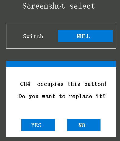
Take the above picture as an example. PS1 initially controls channel 4 by default. When PS1 is selected again when setting the screenshot switch, the above prompt "Do you want to replace it?" will appear. If you click "YES", PS1 will control the screenshot function and no longer control channel 4; if you click "NO", PS1 will still control channel 4, but not the screenshot function.
PS buttons sound setting
Click 2/2 at the top right corner to switch the setting menu to the Sound setting menu. The sound of buttons PS1, PS2, PS3, PS4, PS5, PSS, and PTS can be set in this menu.
Setting steps: click the blue select box named Auto (because the default factory setting is Auto) can into the sound setting list, and select one of the sound types as the prompt tone. You can listen to it when selected, and you can hear the prompt tone every time you press the button after the selection.
Auto: indicates the sound type of the default factory setting.
NONE: indicate without any sound when pressing the button; eight types of beeps can be selected.
Audio source: indicate the type of sound, "Buzzer" and "Warning voice" can be selected.
Beep1-8: buzzer type, eight types can be selected.
Warning 1-20: warning type, twenty types can be selected.
System voice: There are 55 kinds of function voice prompts by default. When the function of the button is set to be the same as the voice function here, you can rotate the corresponding voice broadcast prompt here. For example, After the DT1 trim key is used to control the four-wheel steering, you can select "4wd double" here, and the transmitter will broadcast the voice after selecting it.
Customized voice: Users can make custom prompt voice production through text-to-speech software, and then copy the voice file to the transmitter, where they can choose their own voice. For detailed information on how to make their own voice, please refer to 2.12 Customized Voice Production.
Stop audition: The button at the bottom of the screen is OFF, and the background color of the select box is grey, indicating that when selecting the buzzer or warning voice, the transmitter will broadcast the prompt tone that you have selected.
The button at the bottom of the screen is ON, and the background color of the select box is blue, indicating that when selecting the buzzer or warning voice, the transmitter will not broadcast the prompt tone that you have selected.
This stops the trial listening function only applies to the Key tone-setting menu.
Attention:
PSS indicates that push the steering switch.
PTS indicates the Push throttle switch.
PSxUP: the sound set for the button PS1/PS2/PS3/PS4/PS5 when loosening it.
PSxDOWN: the sound set for the button PS1/PS2/PS3/PS4/PS5 when pressing it.
2.2.9 Double Ratio (Dual Rate)
Double ratio is used to decrease the servo travel of each channel. It cannot increase the travel of each channel. At the same time, it is different from the end point setting, which needs to set the travel on both sides of the channel separately. A double ratio will affect the travel on the left and right sides at the same time. If the ratio of throttle is reduced, the ratio of the forward and braking control of the model will be reduced. The setting range is from 0 to 100, and the default value is 100.
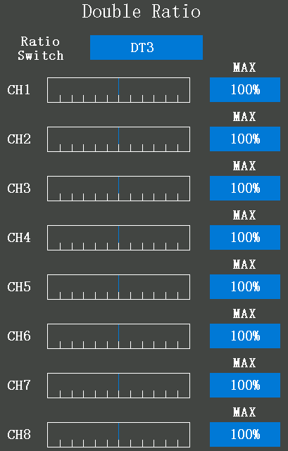
Ratio switch: Switch used to switch the end point. you can assign PS1, PS2, PS3, PS4, PS5, steering switch (SS), trigger switch (TS), DT1, DT2, DT3, DT4, and DL1 to control it. "NULL" means to directly execute the current ratio, with no switch to control it.
Tutorial of Double Ratio:
2.2.10 Fail-safe
This function sets the servo operation position when transmitter signals cannot be received by the receiver for some reason.
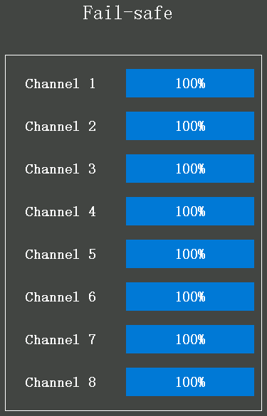
The initial value is 0%, which means that when the transmitter signals cannot be received by the receiver, the throttle will stop to output, and the servo will keep its position immediately before the reception was lost.
You can set the value to make the servo move to a preset position you want when the fail-safe function is activated according to your cars or boats. For gasoline engine cars, for safety, we recommend that this fail-safe function be used to set the throttle channel in the direction in which the brakes are applied.
2.2.11 Receiver setting
RC8X is standard packed with an R8FG receiver. The binding of them has already finished by default. If you purchase a new compatible receiver, binding needs to be done before using it. The binding steps can refer to as 1.3.2 Binding
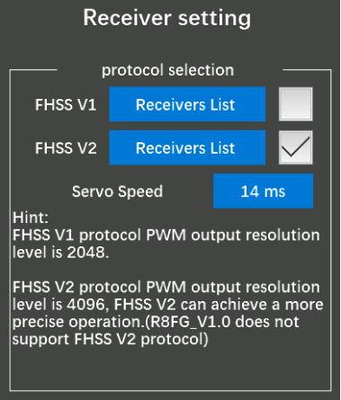
Receiver select: FHSS V1 receivers have a PWM output resolution of 2048, and FHSS V2 receivers have a PWM output resolution of 4096. The higher the resolution, the more delicate the angle of servo motion.
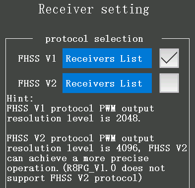
You can click "Receivers List" to check whether the receiver you are currently using belongs to this list. If yes, please click the box on the right to confirm the current receiver type. If not, please do not select this list.
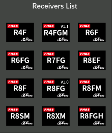
FHSS V1 Receiver List
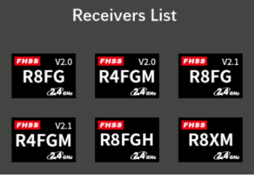
FHSS V2 Receiver List
Servo Speed:
1. Transmitter: It is necessary to update the firmware of RC8X to V1.1.5 or above, and then select FHSS V2 protocol to display this option. Servo speed can be selected from 14ms, 4ms, and 3ms. The factory default servo speed is 14ms (analog servo speed), 4ms and 3ms (digital servo speed).
2. Receiver: If you are using a digital servo, you need to choose a servo speed of 4ms or 3ms. Please confirm whether the receiver you are using supports digital servo. Currently, RadioLink receivers that support digital servo include R8FG V2.1, R4FGM V2.1, and R8FG and R4FGM receivers with a factory date of 2023/4/26 and later. Other versions of RadioLink receivers do not support digital servo. Even if 4ms or 3ms is selected when using them, the default servo speed is 14ms. RadioLink will continue to add other models of receivers that support digital servos in the future. Please pay attention to RadioLink official website.
3. Status indication: When switching the servo speed, the green LED light of the receiver will flash twice, which means that the switching of the servo speed is successful; if the green LED of the receiver does not flash when switching the servo speed of the servo, it means that the switching of the servo speed of the servo is unsuccessful or the current receiver does not support digital servos.
Attention:
1.RC8X comes with R8FG receiver. R8FG V1.0 (production date before Feb. 6, 2023) only supports FHSS V1 protocol, not FHSS V2 protocol; R8FG V2.0 and later versions (production date on or after Feb. 6, 2023) only support FHSS V2 protocol. Before operating the model, please make sure protocol of the receiver is selected correctly, otherwise some functions will not work properly.
2. The receivers that compatible with the RC8X is keep updating, please pay attention to RadioLink official website www.radiolink.com to get the latest firmware to check the newly launched receiver. This page is only to display the receiver models which are compatible with the RC8X.
2.2.12 Subsidiary ID mode
RC8X can bind with multiple receivers. When RC8X and multiple receivers have been bound successfully, RC8X and all successfully paired devices are turned on at the same time. There are two ways to use them:
1. When the Subsidiary ID function is turned off, RC8X can control multiple devices at the same time.
2. When the Subsidiary ID function is turned on, RC8X can control the specified device according to the selected Subsidiary ID. RC8X has 16 groups of Subsidiary ID functions, and each ID corresponds to a receiver. Set the Subsidiary ID first. When all the devices are turned on, you can control one of the devices through the Subsidiary ID function. At this time, the other devices are on standby.
For example: Bind RC8X with a truck and a car and turn all of them on. First, use RC8X to control the car to run to the bucket of the truck, and then switch the receiver ID on the truck to drag the car back to the destination.
Subsidiary ID mode setting steps:
1.Tap the button at the right of the "Subsidiary ID mode" to change it from "OFF" to "ON". Set the ID number according to your cars or boats and then finish the bind and parameters set for each receiver.
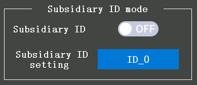
2. Once finished the Subsidiary ID mode setting, the corresponding ID number will be displayed on the main interface of RC8X. (For example, ID_1) Change the ID number by clicking "-" or "+", click Reset will make the ID number back to ID_0.
2.3 Telemetry setting
2.3.1 Receiver signal
In this menu, the current signal strength (RSSI) of the receiver will display, and the low RSSI value alarm mode, the vibration mode, the alarm limit, and the alarm interval can be set.
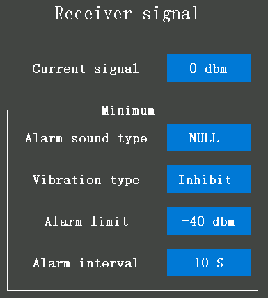
Current signal: the initial value of the current signal is -100dBm. After the RC8X has bound to the receivers which have the signal strength telemetry function, the RSSI value will display here and the value will vary with the distance between the receiver and the transmitter.
Alarm mode type: it defaults "NULL", which means that if the value of the current signal is lower than the alarm limit you have set, the transmitter will alarm, sound, and 20 kinds of warnings can be set.
Vibration mode: it defaults "Inhibit", Mode1, Mode2, and Mode3 can be selected.
Alarm limit: the initial low RSSI alarm value is -40dbm, which means if the current signal is less than -40dbm, the transmitter will alarm with sound or warning. The low RSSI alarm value can be set from 0 dBm to -100 dBm, the best RSSI alarm value is depending on the control range test.
Alarm interval: the interval period for the alarm, if the low RSSI alarm value is less than the alarm value you have set, it defaults to alarm once every 10 seconds, the alarm interval time can be customized.
Attention:
- If the settings have been finished, but the transmitter and receiver are not properly connected, the transmitter will also issue an alarm prompt.
- When the distance between the transmitter and the receiver is 60 centimeters, it is normal that the RSSI value is within the range of 0 to -30dBm. The closer the value is to 0, the stronger the signal is.
- This function can not only alarm when the receiver signal is weak but also can be used to test whether the transmitter and the receiver device are communicating normally, the test steps as: https://www.radiolink.com.cn/RSSI_measurement_methods
2.3.2 Transmitter voltage
please refer to 2.1.5 Battery (Transmitter Battery Voltage)
2.3.3 Receiver voltage
The input voltage of the receiver.
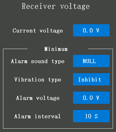
Current voltage: the initial voltage is 0.0V. When the receiver binds success to the RC8X, the current input voltage of the receiver will display here.
Alarm sound type: it defaults "NULL", which means that if the current receiver input voltage is lower than the alarm voltage you have set, the transmitter will alarm, sound, and 20 kinds of warning can be selected.
Vibration type: it defaults "Inhibit", Mode1, Mode2, and Mode3 can be selected.
Alarm voltage: the initial voltage is 4.5V, which means that when the current receiver input voltage is lower than 4.5V, the transmitter will alarm, and 3.3V to 12V can be selected.
Alarm interval: the interval period for the alarm, if the current receiver input voltage is lower than the alarm voltage you have set, it defaults to alarm once every 10 seconds, the alarm interval time can be customized.
2.3.4 Engine battery voltage
Please refer to 1.3.3 Receiver Connection
2.3.5 Telemetry broadcast
Auto: broadcast the sensor status automatically with sound, such as the current signal strength, the current receiver input voltage, the current transmitter voltage, the EXT voltage, etc.

The button at the right of "Auto" is OFF, and the background color of the select box is grey, indicating that the broadcast automatically function is turned off.
The button at the right of "Auto" is ON, and the background color of the select box is blue, indicating that the broadcast automatically function is turned on.
Switch: PS1/PS2/PS3/PS4/PS5/Steering/Trigger can be set to turn on the sensor status and time broadcast automatically function. If both the sensor status and time broadcast automatically function are turned on, they will be broadcasted according to the order list of the menu.
Stop broadcast button: PS1/PS2/PS3/PS4/PS5/Steering/Trigger can be set to stop the current broadcast.
Broadcast interval: the interval period for broadcast, if the sensor status and time broadcast automatically function has turned on, it defaults to alarm once every 1 minute, the alarm interval time can be customized.
2.4 Racing menu
2.4.1 Steering curve
This function is used to change the sensitivity of the steering servo around the neutral position. It has no effect on the maximum servo travel. Also, the "Fine tune" function is which can adjust the rate for left and right separately.
Type: EXP (Steering Exponential) and VTR can be selected, it defaults to the EXP type.
If the curve type selects EXP, the steering operates will change with a curved curve from the neutral point to the endpoint. While if the curve type selects VTR, the steering operation will change with a linear curve from the neutral point to the high point.
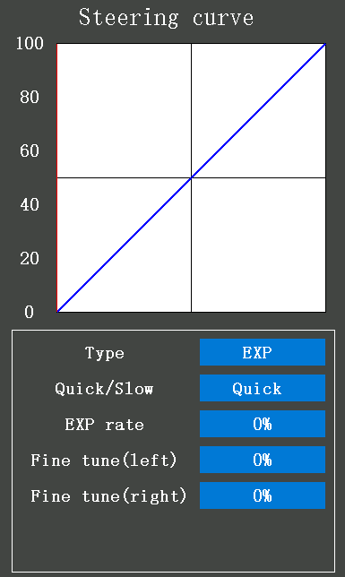
EXP curve: It is used to adjust the sensitivity of the direction wheel both in a neutral position and ends. Taking the center line of the EXP as the demarcation point, if set the steering curve type is as Quick EXP curve and the EXP rate is 100%, the steering acceleration is completed in the front 80% of the rudder amount range, thus achieving the effect that the first half of the rudder amount changes faster than the second half. The slow EXP curve is the opposite.
Quick/Slow: +100 indicates the quick EXP rate, and -100 indicates the slow EXP rate.
The vertical cursor line moves in conjunction with the operation of the steering wheel.
EXP rate: the initial value of EXP rate is 0%, -100% to +100% can be selected. With the change of this value, the sensitivity of left and right steering is adjusted in the same ratio.
If you want to make the steering get a higher sensitivity or make steering more gentle, click "+" to increase the value, or click "-" to decrease the value. When the value of EXP is not 0%, click Quick or Slow to switch the value quickly.
Fine-tune (left): To set the right and left steering curves separately. The initial value is 0%, -200% to +200% can be selected.
Fine-tune (right): To set the right and left steering curves separately. The initial value is 0%, -200% to +200% can be selected. Click "-" can decrease the value, and click "+" can increase the value.
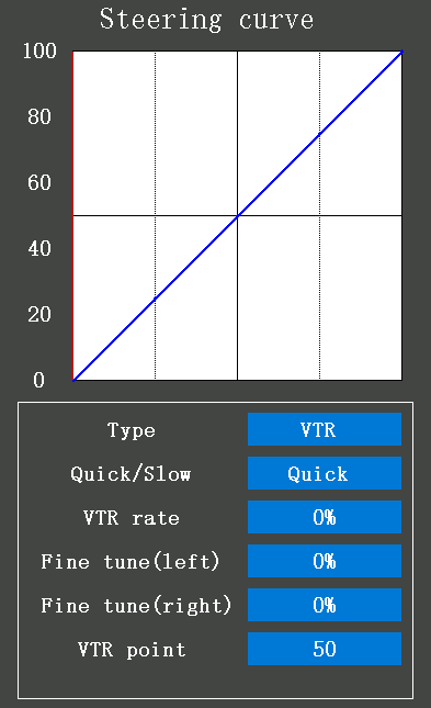
VTR curve: If the curve type selects VTR, the steering operates will change with a linear curve from the neutral point to the high point. Taking the center line of the VTR as the demarcation point, if set the steering curve type is as Quick VTR curve and the VTR rate is 100%, the steering acceleration is completed in the front 80% of the rudder amount range, thus achieving the effect that the first half of the rudder amount changes faster than the second half. The slow VTR curve is the opposite.
Quick/Slow: +100 indicates the quick VTR rate, and -100 indicates the slow VTR rate.
The vertical cursor line moves in conjunction with the operation of the steering wheel.
VTR rate: the initial value of the VTR rate is 0%, -100% to +100% can be selected. With the change of this value, the sensitivity of left and right steering is adjusted in the same ratio.
If you want to make the steering get a higher sensitivity or make steering more gentle, click "+" to increase the value, or click "-" to decrease the value. When the value of VTR is not 0%, click Quick or Slow to switch the value quickly.
Fine-tune (left): To set the right and left steering curves separately. The initial value is 0%, -200% to +200% can be selected.
Fine-tune (right): To set the right and left steering curves separately. The initial value is 0%, -200% to +200% can be selected. Click "-" can decrease the value, and click "+" can increase the value.
VTR point: The VTR point is set to limit the rudder amount range of the high points. The initial value is 50, which means the high point will reach the half rudder amount range of the left or right steering servo, 0 to 100 can be selected.
2.4.2 Throttle curve
This function makes the throttle high-side direction servo operation quicker or milder. It does not affect the servo maximum operation amount. Throttle curve type: three kinds of curves EXP, VTR, and Multiple point curves can be selected.
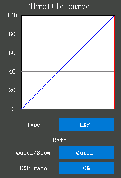
EXP curve: It is used to adjust the throttle operation change with a curved curve from the neutral position to the high point.
Quick/Slow: +100 indicates the quick throttle curve rate, and -100 indicates the slow throttle curve rate. The vertical cursor line moves in conjunction with the operation of the throttle trigger.
EXP rate: the initial value of EXP rate is 0%, -100% to +100% can be selected. If you want to make the throttle high-side direction servo operation quicker or milder, click "+" to increase the value, or click "-" to decrease the value. When the value of EXP is not 0%, click Quick or Slow to switch the value quickly.
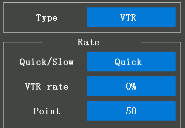
VTR curve: It is used to adjust the throttle operation change with a linear curve from the neutral point to the high point.
Quick/Slow: +100 indicates the quick throttle curve rate, and -100 indicates the slow throttle curve rate. The vertical cursor line moves in conjunction with the operation of the throttle trigger.
VTR rate: the initial value of the VTR rate is 0%, -100% to +100% can be selected. If you want to make the throttle high-side direction servo operation quicker or milder, click "+" to increase the value, or click "-" to decrease the value. When the value of EXP is not 0%, click Quick or Slow to switch the value quickly.
VTR point: The VTR point is set to limit the rudder amount range of the high points. The initial value is 50, which means the high point will reach the half rudder amount range of the left or right steering servo, 0 to 100 can be selected.
Point: When the landform is good and the ground surface has a good grip, set each curve to the plus [+] side (quick rate). When the road surface is slippery and the drive wheels do not grip it, set each curve to the minus [-] side (slow rate).
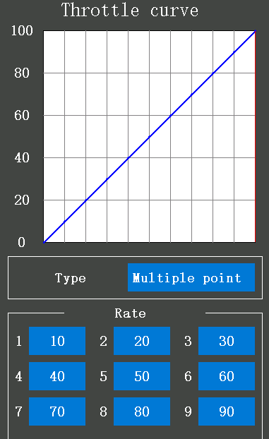
Multiple points: 9 points can be set between the neutral position and the high point.
Point 1 to point 9:
Point 1: the initial value is 10, and 0 to 100 can be selected.
Point 2: the initial value is 20, and 0 to 100 can be selected.
Point 3: the initial value is 30, and 0 to 100 can be selected.
Point 4: the initial value is 40, and 0 to 100 can be selected.
Point 5: the initial value is 50, and 0 to 100 can be selected.
Point 6: the initial value is 60, and 0 to 100 can be selected.
Point 7: the initial value is 70, and 0 to 100 can be selected.
Point 8: the initial value is 80, and 0 to 100 can be selected.
Point 9: the initial value is 90, 0 to 100 can be selected, click "-" can decrease the value, and click "+" can increase the value.
2.4.3 Brake curve
This function makes the throttle brake side direction servo operation quicker or milder. It has no effect on the servo maximum operation amount.
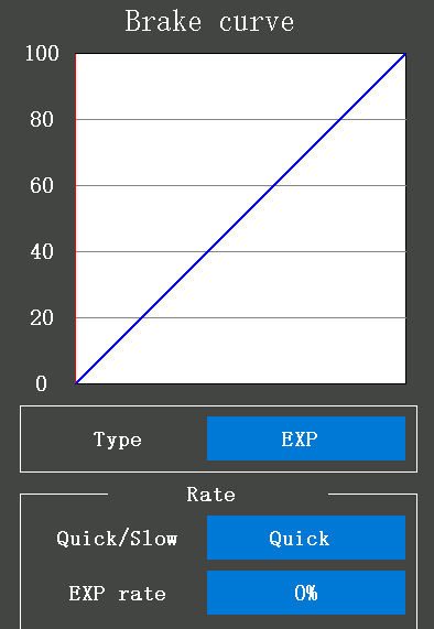
Brake curve type: three kinds of curves, EXP, VTR, and multiple-point curves can be selected.
If the Ratio is set to Forward 100: Brake 0 with the trigger function in the Throttle Setting (Trigger) menu, the brake side will not operate. Since the setting method of each curve is the same as the throttle (forward) side curve, please refer to 2.4.2 Throttle curve
2.4.4 Acceleration
Neutral: This function is designed for adjusting the acceleration of the throttle when it is in the neutral position. Using this function can improve the starting performance of gasoline engine cars by increasing the neutral speed when the car engine starts. The initial value of Neutral is 0%, -50% to 50% can be selected.
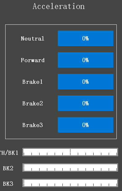
Forward: The servo will jump to the input position at its maximum possible speed. Unlike exponential, which adjusts the whole throttle movement into a curve, throttle acceleration simply "jumps" away from neutral and then leaves the remaining response linear.
Brake1/Brake2/Brake3: same as the Forward. The initial value of Brake1/Brake2/Brake3 is 0%, and 0% to 100% can be selected. 0% means no acceleration when braking and 100% means brake side maximum throttle angle. Operation near the throttle trigger neutral position becomes a sharp rise if set the value of Brake1/Brake2/Brake3 to 100%.
Attention: TH in the servo display on the bottom of the screen indicates Throttle. BK1 indicates acceleration of Brake1, BK2 indicates acceleration of Brake2, and BK3 indicates acceleration of Brake3.
2.4.5 Steering delay
Quick steering operation will cause momentary understeering, loss of speed, or spinning. steering delay function will very helpful in such cases.
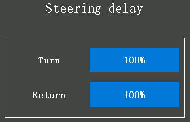
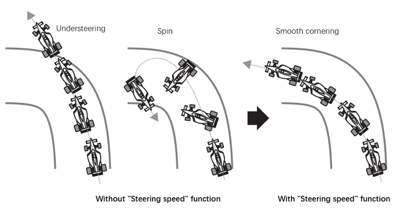
Turn: the initial value is 100%, and 0% to 100% can be selected. 100% means there is no delay.
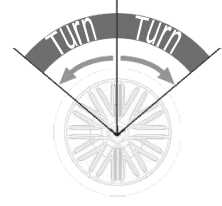
Servo operation is delayed
Return: the initial value is 100%, and 0% to 100% can be selected. 100% means there is no delay.
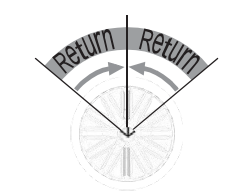
Servo operation is delayed
Attention:
1. This function limits the maximum speed of the steering servo. (Delay function) The steering delay when the steering wheel is operated (Turn direction) and returned (Return direction) can be independently set.
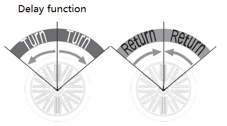
2. If the steering wheel is turned slower than the set speed, the steering servo is not affected.
2.4.6 Throttle delay
Sudden throttle trigger operation on a slippery road will cause the wheels to spin and the vehicle cannot accelerate smoothly. Setting the steering delay function reduces wasteful battery consumption while at the same time permitting a smooth, enjoyable operation.
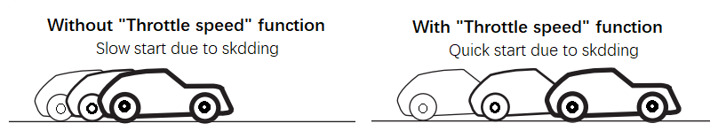
Attention:
Throttle servo (ESC) operation is delayed so that the drive wheels will not spin even if the throttle trigger is operated more than necessary. This delay function is not performed when the throttle trigger is returned and at brake operation.
Mode: All points, High-Low points, and Three-point can be selected.
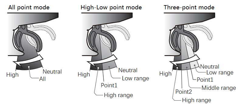
All point: A delay is set over the entire throttle range.
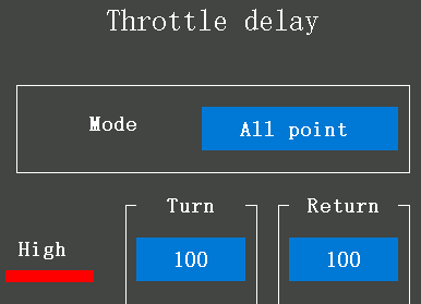
Turn: the initial value is 100, and 1 to 100 can be selected, if the value is 100, it means there is no delay.
The servo operation is delayed.
Return: the initial value is 100, and 1 to 100 can be selected, if the value is 100, it means there is no delay.
The servo operation is delayed.
High-Low point: A delay can be set in 2 ranges with Point 1 as the boundary.
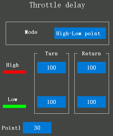
Turn: "Low" and "High" turn direction delay adjustment, the initial value of High or Low turn speed is 100, 1 to 100 can be selected, if the value is 100, it means there is no delay.
The servo operation is delayed.
Return: "Low" and "High" return direction delay adjustment, the initial value of High or Low return speed is 100, 1 to 100 can be selected, if the value is 100, it means there is no delay.
The servo operation is delayed.
Point 1: is for speed switching point adjustment. The initial value is 30, and 0 to 100 can be selected to change the "Low" and "High" switching points.
Three points: A delay can be set in 3 ranges with Point 1 and Point 2 as the boundaries.
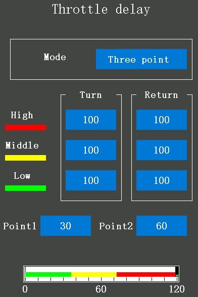
Turn: "Low", "Middle", or "High" turn direction delay adjustment.
The initial value is 100, and 1 to 100 can be selected, if the value is 100, it means there is no delay.
The servo operation is delayed.
Return: "Low", "Middle", or "High" return direction delay adjustment.
The initial value is 100, and 1 to 100 can be selected, if the value is 100, it means there is no delay.
The servo operation is delayed.
Point1/Point2: is for speed switching point adjustment. The initial value of Point1 is 30 and the initial value of Point2 is 60, 0 to 100 can be selected to change the "Low", "Middle", and "High" switching points.
The steering delay "Turn" and "Return" adjustment can be controlled with digital trim DT1 to DT4 or digital dial DL1 etc. with the Trim/Dial select function in the Tools menu.
Attention:
Setting the speed function in the return direction slows the deceleration of the car body, so please be careful to set it carefully.
2.4.7 Cruise Control
Cruise control can keep the throttle output to a fixed value. When cruise control is enabled, the throttle output will jump to the set value regardless of the current position of the throttle trigger. For example, when using RC8X on a climbing car, you can turn on the cruise control with one switch, and the climbing car can maintain a constant speed without pulling the trigger.
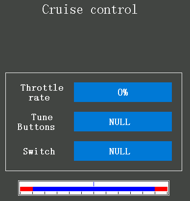
Throttle rate: The fixed output value of the throttle. The setting range is from 0 to +100%.
Tune Buttons: DT1/DT2/DT3/DT4/DL1 can be selected to adjust the throttle rate.
Switch: PS1/PS2/PS3/PS4/PS5/Steering/Trigger can be selected to turn on or turn off the cruise control function.
2.4.8 Idle up
The function is used to improve engine starting performance by raising the idling speed when starting the engine of a Gas power car/boat.
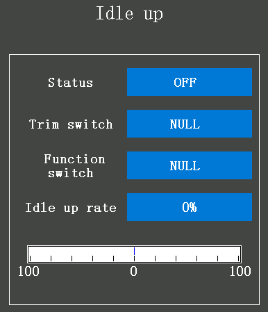
Status: to turn on or turn off the Idle up function.
Trim switch: DT1/DT2/DT3/DT4/DL1 can be selected to adjust the idle up rate, "NULL": indicate that no switch is set to adjust the idle up rate, but you can also click the value next to the idle up rate in the menu, and then press the [-] or [+] buttons at the bottom of the screen to adjust the rate.
Function switch: PS1/PS2/PS3/PS4/PS5/Steering/Trigger can be selected to turn on or turn off the idle up function, "NULL": indicate that no switch is selected. If the "Status" is set to ON, and the "Function switch" is set to "Null", the transmitter will execute the current idle up rate by default, and it will not automatically turn off.
Idle up rate: The rate can be set from -50% to +50%. You can use the trim switch to quickly adjust the idle up rate, or you can click the value next to the idle up rate, and then press the [+] and [-] buttons at the bottom of the screen to adjust the value.
2.4.9 Throttle Setting (Trigger)
The ratio is the function that is set for servo neutral. Three modes can be selected: Forward 50: Brake 50, Forward 70: Brake 30, and Forward 100: Brake 0.
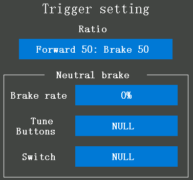
This function allows the selection of the forward side and brake (reverse) side operation ratio by changing the neutral position of the throttle servo.
Forward 50: Brake 50: We regard the entire throttle range as 100%. Set the ratio as Forward 50: Brake 50 means that both forward and brake account for 50%, and the brake starts at the midpoint of the throttle range.
Forward 70: Brake 30: We regard the entire throttle range as 100%. Set the ratio as Forward 70: Brake 30 means that the forward account for 70% and the brake only accounts for 30% of the throttle range. Release the throttle trigger will not brake, you must keep pulling the throttle trigger to the brake direction (goes through the new midpoint which reaches 70% of the entire throttle range) to brake.
Forward 100: Brake 0: We regard the entire throttle range as 100%. Set the ratio as Forward 100: Brake 0 means that the forward account for 100% and the brake account for 0%, release the throttle trigger and brake immediately. The car cannot go backward if the Ratio selects Forward 100: Brake 0.
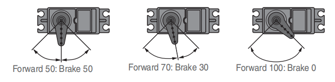
Neutral brake
This is a function select switch function. The neutral brake function must specify a switch to turn it on or off. The brake rate can be set from 0% to 100%. The neutral brake, which applies the brakes at the neutral position of the throttle trigger, can be set. Confirm that the ESC is in the neutral position and the set is in operation mode before setting the neutral brake function switch to ON.
Brake rate: the value of neutral brake rate is 0%, 0% to 100% can be set, and the rate value must be set depending on the ratio mode.
Tune Buttons: DT1/DT2/DT3/DT4/DL1 can be selected to adjust the brake rate.
Switch: PS1/PS2/PS3/PS4/PS5/Steering/Trigger can be selected to turn on or turn off the neutral brake function.
"NULL": indicate that the function is not enabled.
The ESC neutral brake function and Neutral brake function of the Throttle setting can be used simultaneously. However, when the setting is difficult to understand, we recommend that only one neutral brake function be used.
When the neutral brake function is "ON", the neutral brake rate adjustment is automatically assigned to the throttle trim (DT1, DT2, DT3, DT4, or dial button DL1).
The throttle side EPA function or ATL function setting also affects neutral brake side operation. The Idle-up 2.3.11 Idle-up or Engine Cut 2.5.9 Engine cut function has priority.
2.4.10 Traction control (T.R.C)
Trigger operation with cornering on a slippery road surface is hard to get traction and smooth cornering cannot be done. By intermittently operating the throttle, you can smoothly navigate and travel on topological lines. Also, with a drift car, by intermittently operating the motor in the high point direction, a pseudo reverberator engine sound can be reproduced.
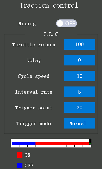
Mixing: The button at the right of "Mixing" is OFF, and the background color of the select box is grey, indicating that the Traction control function is turned off. The button at the right of "Mixing" is ON, and the background color of the select box is blue, indicating that the Traction control function is turned on.
Throttle return: Set the ratio that the servo returns to the slow side of the trigger operation. If set to 0%, the traction control function will not work. At 50%, it returns to the neutral position at 50% (half), 100% of the trigger operation amount.
Delay: Set the delay from when the throttle is operated until when the traction control operation starts. When set to 0%, the traction control function works without delay. At 50%, the traction control function works approximately 0.5 seconds later, and the traction control function works about 1 second later at 100%.
Cycle speed: Sets the pulse speed (cycle speed). The initial value is 10, and 0 to 30 can be selected. The smaller the set value, the faster the pulse cycle.
Interval rate: Set the ratio of the time to operate on the high side and the time to operate on the slow side in the pumping operation. The initial ratio is 0, which can be set to +9 - +0 - -9 in 19 steps.
-9 indicates brake application time becomes shortest which means brakes lock with difficulty.
9 indicates brake application time becomes longest which means brakes lock easily.
Trigger point: When the traction control mixing is turned on, in the throttle operation, set the position that triggers the traction control function to start to work. The initial value is 30, and 5 to 95 can be selected.
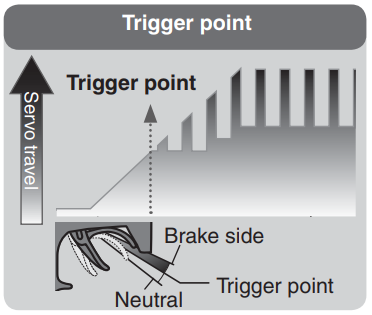
Trigger mode: Normal or Reverse can be selected.
"Normal" means the high range from the trigger point to the operating range. "Reverse" means the operating range from neutral to the trigger point.
The traction control can select the switch PS1, PS2, PS3, PS4, PS5, Steering switch, and Trigger switch to turn on or turn off, the switch can select in the Switch select menu.
2.4.11 A.B.S
When the brakes are applied while cornering with a 4-Wheel Drive or other types of vehicles, understeer may occur. The tendency to understeer can be eliminated and corners can be smoothly cleared by using this function. Three sets of A.B.S can be set. A.B.S function can be turned on or turned off by pressing the A.B.S trigger button or the Steering trigger button.
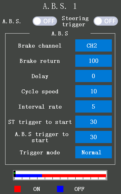
A.B.S: The button at the right of "A.B.S" is ON, and the background color of the select box is blue, indicating that the A.B.S function is turned on. Push forward the throttle trigger to trigger the A.B.S function.
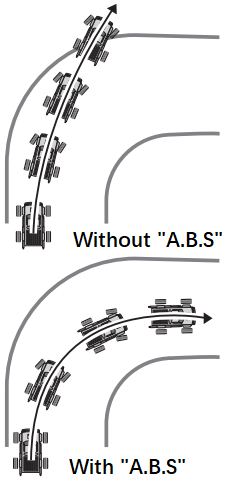
Steering trigger: The button at the right of "Steering trigger" is ON, and the background color of the select box is blue, indicating that when the vehicle is performing a braking operation while operating steering and the steering amount is greater than the value of the "ST trigger to start", the A.B.S function will be triggered, if the steering amount is less than the value of the "ST trigger to start", the A.B.S function will not be triggered.
Brake channel: A.B.S.1 is the default same as the throttle channel, and cannot be customized, the channel of A.B.S.2 and A.B.S.3 can be customized, and CH1 to CH8 can be selected.
Brake return: Sets the rate that the trigger operation corresponds to the servo returns to position when brake release. When set to 0%, the A.B.S function is not performed. When set to 50%, the servo returns 50% (1/2) of the trigger operation amount and when set to 100%, the servo returns to the neutral position.
Delay: Sets the delay from brake operation to A.B.S operation. When set to 0%, the A.B.S function is activated without any delay. At 50%, the A.B.S function is activated after a delay of approximately 0.7 seconds and at 100%, the A.B.S function is activated after a delay of approximately 1.4 seconds.
Cycle speed: Sets the pulse speed. The smaller the value set, the faster the pulse cycle. The initial value is 10, and 0 to 30 can be selected.
Interval rate: Sets the proportion of the time the brakes are applied and the time the brakes are released by pulse operation. The initial value is 0, and -9 to 9 can be selected.
ST trigger to start: steering wheel will trigger the A.B.S function when:
① the Steering trigger function is turned on: the button at the right of "Steering trigger" is ON, and the background color of the select box is blue.
② the vehicle is performing a braking operation while operating steering
③ the steering amount is greater than the value of the "ST trigger to start"
A.B.S trigger to start: Sets the trigger point that the A.B.S function is performed. The initial value is 30, and 5 to 95 can be selected.
Tigger mode: Normal and Reverse can be selected. "Normal" indicates the neutral trigger point is the range of motion. "Reverse" indicates the range from the trigger point to the full brake side is the operating range.
2.4.12 Motor Start
If the track is slippery and you begin to accelerate by pushing the trigger to full throttle, the car wheels will spin and will not accelerate smoothly. When the Start function is activated, merely operating the throttle trigger slowly causes the throttle servo to automatically switch from the set throttle position to a preset point so that the tires do not lose their grip and the car accelerates smoothly.
Attention:
1. When the throttle trigger moves to the trigger point, the throttle servo moves to the preset point position.
2. This function is effective only for the first throttle trigger operation at starting and must be activated before every start.
3. When the throttle trigger is returned slightly, the Start function is automatically deactivated and the set returns to normal throttle trigger operation.
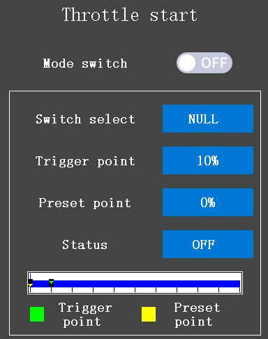
Mode switch: The button at the right of the "Mode Switch" is OFF, and the background color of the select box is grey, indicating that the Throttle start function is turned off. The button at the right of the "Mode Switch" is ON, and the background color of the select box is blue, indicating that the Throttle start function is turned on.
Switch select: PS1/PS2/PS3/PS4/PS5/Steering/Trigger can be set to turn on or turn off the Throttle start function.
Trigger point: When the throttle trigger is moved to the preset position (the value trigger point preset) trigger the Throttle start function. The initial value of the Trigger point is 5%, and 5% to 95% can be selected.
Preset point: When the throttle trigger is operated slowly so that the wheels will not spin. Then, pull the throttle trigger to the value of the Preset point, and the car will accelerate to the set speed automatically. The initial value of the Preset point is 0%, and 0% to 100% can be selected. The throttle trigger the Preset point requires:
① The throttle start function is turned on (the Mode switch is ON)
② The throttle rudder amount reaches the value of the "Trigger point".
③ The Status is "Ready".
Status: indicates the current throttle start status, "OFF" and "Ready" can be selected, controlled by the switch that is set in "Switch select". In the "Ready" state, if the throttle trigger is operated to the position of the "Trigger point", the throttle servo will accelerate to the set speed automatically. It is canceled when the throttle trigger is returned.
2.4.13 Engine cut
When pressing the Engine cut function switch, the throttle servo will move to the presets position without regard to the throttle trigger position. This is convenient when used to cut the engine of cars, boats, etc.
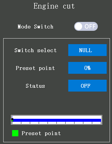
Mode Switch: The button at the right of "Mode Switch" is OFF, and the background color of the select box is grey, indicating that the Engine cut function is turned off. The button at the right of "Mode Switch" is ON, and the background color of the select box is blue, indicating that the Engine cut function is turned on.
Switch select: PS1/PS2/PS3/PS4/PS5/Steering/Trigger can be set to turn on or turn off the Engine cut function.
Preset point: the rudder amount when the engine has cut. When pressing the Engine cut function switch with the Engine cut function turned on, the throttle servo (motor) value is locked in the preset position and does not operate even if the throttle trigger is operated. If the servo was operated in the wrong setting, you may lose control of the car/boat. The initial value of the Preset point is 0%, and 0% to 100% can be selected.
Status: indicates the throttle state when the engine has cut, "Ready" and "Trigger" can be selected, controlled by the switch that is set in "Switch select". In the "Trigger" state, if the Engine cut function is turned on, the throttle servo (motor) value is locked in the preset position and does not operate even if the throttle trigger is operated.
2.5 Mixing menu
2.5.1 Steering mixing
This mixing function uses 2 servos to control the left and right steering individually. Left and right steering can be set independently to make the cornering smoothly possible. By using the "Steering mixing" function, the motions of the servos on the left and right sides of the steering can be adjusted at the same time. The right-side steering servo or the left-side steering servo connects to receiver channel 1 and the other side connects to the receiver auxiliary channels.
Both left and right servo control channels can be customized. After the left and right servos are adjusted individually, Ackermann can also be adjusted by the Ackermann rate. In addition, the left and right steering are operated in the opposite direction by the switch. An emergency brake function by steering can also be set.
Attention: The changes in the rudder amount will display at the bottom of this page (Steering mixing menu).
Mixing: The button at the right of "Mixing" is OFF, and the background color of the select box is grey, indicating that the Steering mixing function is turned off. The button at the right of "Mixing" is ON, and the background color of the select box is blue, indicating that the Steering mixing function is turned on.
Ackermann: Set Ackermann rate to make the cornering smoother. The initial value is 0%, -100% to 100% can be selected.
Rate: is for the left and the right steering mixing rate adjustment. The initial value is 100%, and 0% to 100% can be selected.
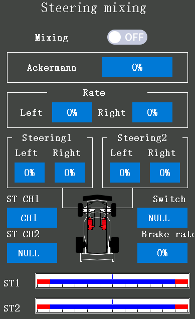
Steering 1: is for the servo1 steering angle adjustment. The left and the right servo1 steering angle can be set separately. The initial value of left and right is 100%, and 0% to 120% can be selected.
Steering 2: is for the servo2 steering angle adjustment. The left and the right servo2 steering angle can be set separately. The initial value of left and right is 100%, and 0% to 120% can be selected.
ST CH1:is for setting the controlled channel of the servo1. "NULL" indicates that the servo1 is not controlled by any channel, channels 1 to channel 8 can be selected.
ST CH2:is for setting the controlled channel of the servo2. "NULL" indicates that the servo2 is not controlled by any channel, channels 1 to channel 8 can be selected.
Attention: the servo1 and servo2 controlled channels cannot be occupied, if the channels have been occupied, you need to go to the "Channel setting" menu to set the corresponding channel to "NULL" or select the other channels that have not to be occupied.
Switch: PS1/PS2/PS3/PS4/PS5/Steering/Trigger can be set to turn on or turn off the Steering brake function.
Brake rate: is for the brake angle adjustment. The initial value is 0%, -120% to 120% can be selected.
2.5.2 Brake mixing
This function is used when the front and rear brakes must be adjusted independently, for example, in a 1/5 scale GP car. This mixing uses channel 2 to control the rear brakes and the auxiliary channel or auxiliary channel servo to control the front brakes. Or, control channel 2 by the independent throttle and control the rear and front brakes with the auxiliary channel. In addition, mixing which varies the auxiliary channels' brake rate in proportion to steering operation is also possible.
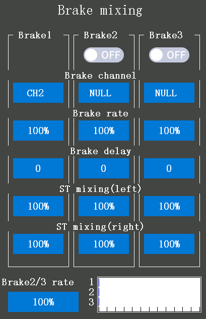
Brake2/Brake3 button: The button under the "Brake1" or "Brake2" is OFF, and the background color of the select box is grey, indicating that the Brake1/Brake2 mixing function is turned off. The button under the "Brake1" or "Brake2" is ON, and the background color of the select box is blue, indicating that the Brake1/Brake2 mixing function is on.
Brake channel: Brake1 is default controlled by channel2, Brake2 and Brake3 can be customized, and channel 1 and channel 8 can be selected.
Brake rate: is for the brake rudder amount adjustment. The brake amount of both Brake 2 and Brake 3 can be adjusted individually. The Brake1 brake rate is linked with the throttle channel (ATL) setting. The initial value is 100%, and 0% to 100% can be selected.
Brake delay: is for the delay amount adjustment. The initial value is 0 which means no delay, 0 to 100 can be selected. Since a delay at all the brakes is dangerous, the Brake delay of Brakes 1, 2, and 3 will not be applied at the same time. For example, Brake1, 2, and 3 are all turned on, when a delay is applied to Brake2 and 3, a delay cannot be applied to Brake1. When a delay must be applied to Brake1, the Brake2 or Brake3 delay must be set to "0".
ST mixing(left): for the left steering mixing adjustment. Use this function when you want to soften the brakes when the steering is operated. The initial value is 0%, and 0% to 100% can be selected. The smaller the value, the weaker the front brakes. If set the value to "100", the steering mixing is not performed.
ST mixing(right): for the right steering mixing adjustment. Same as the ST mixing(left).
Brake 2/3 rate: for the Brake 1 and 2 amount adjustments.
If the trigger ratio is set to Forward 100: Brake 0 with the trigger function in the Throttle Setting (Trigger) menu, the brake side operation will stop working. When using the brake mixing function, set the trigger mode to Forward 70: Brake 30 or Forward 50: Brake 50.
2.5.3 Gyro mixing
This function can be used to set the built-in gyroscope of the receiver and the external professional car gyroscope function individually. You can use the auxiliary channel switch or button to adjust the gyroscope sensitivity.
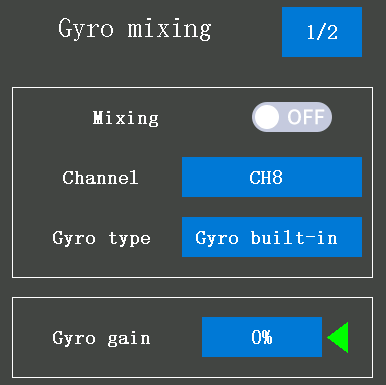
Gyro mixing1/2
Mixing: The button at the right of "Mixing" is OFF, and the background color of the select box is grey, indicating that the built-in gyroscope function is turned off. The button at the right of "Mixing" is ON, and the background color of the select box is blue, indicating that the built-in gyroscope function is turned on.
Channel: the channel to control the built-in gyroscope, defaults controlled by channel 8, channel 1 to channel 8 can be selected.
Gyro type: Gyro mixing type selection. Gyro built-in, Gain1, Gain2, and Gain4 can be selected.
1) Gyro built-in: it means the current working gyro is the built-in gyroscope of the receiver. How to make the gyro function of the receiver R8FG enabled? Please refer to: 1.3.5 Gyro Function of R8FG
2) Gain1/Gain2/Gain4: to set parameters for the external professional car gyroscope. One of the auxiliary channels can be selected as the gain steering channel. Mounting method and handling of the car gyroscope, please refer to the gyro instruction manual.
Gain1: one gain only
Gain2: a group of gyro gains, can switch between Gain1 and Gain2
Gain4: two groups of gyro gains, 2 gains can be set in one group, can switching from Gain1 and Gain2, Gain3 and Gain4.
Gain mode: Normal and AVSC modes can be selected. The AVCS mode increases straight running stability more than the Normal mode. The initial mode is AVSC (the value is 0%), -120% to 120% can be selected, -120% to -1% indicate Normal mode and 0% to 120% indicate AVSC mode.
*AVCS: Angular Vector Control System
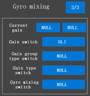
Gyro mixing 2/2
Click 1/2 at the top right corner to switch the setting menu from the built-in gyroscope setting menu to the 2/2 external gyroscope setting menu.
Current gain: Group1 and Group2 can be selected, Group1 including Gain1 and Gain2, Group2 including Gain3 and Gain4.
Gain switch: DT1/DT2/DT3/DT4/DL1 can be set to adjust the gyro sensitivity, if the Gain switch is selected as "NULL", it means the gyro sensitivity only can be adjusted by clicking the "+" and "-" in Gyro mixing1/2 menu.
Gain group type switch: if the Gyro group type selected Gain4, a switch should be set to switching between Group 1 and Group 2. PS1 /PS2 /PS3 /PS4 /PS5 /Steering/Trigger can be selected. If the Gain group type switch selects "NULL", then only one group of gyro gain can be selected at a time.
Gain type switch: if the Gyro type selected Gain2 or Gain4, a switch should be set to switching between Gain1 and Gain2 or Gain3 and Gain4. PS1/PS2/PS3/PS4/PS5/Steering/Trigger can be selected. If the Gain type switch selects "NULL", then only one gain of each group can be selected at a time.
Gyro mixing switch: same function as the "Mixing" button at the menu of Gyro mixing1/2.
Click 2/2 at the top right corner to switch the setting menu from the external gyroscope setting menu back to the 1/2 built-in gyroscope setting menu.
2.5.4 4WS mixing
4WS mixing 1/2
4WS (4-Wheel Steering): This function can be used for crawlers and other 4WS-type vehicles. It uses channel 1 to control front-side steering and one auxiliary channel to control rear-side steering.
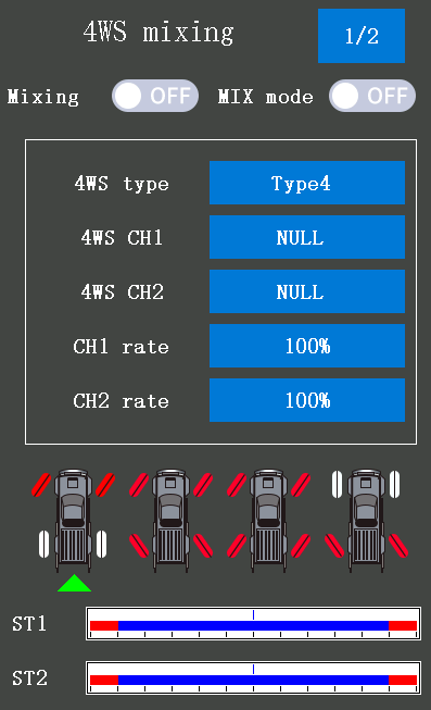
Mixing: The button at the right of "Mixing" is OFF, and the background color of the select box is grey, indicating that the 4WS mixing function is turned off. The button at the right of "Mixing" is ON, and the background color of the select box is blue, indicating that the 4WS mixing function is turned on.
MIX mode: The button at the right of "MIX mode" is OFF, and the background color of the select box is grey, indicating that the EXP function of channel1 and other settings are not mixed. The button at the right of "MIX mode" is ON, and the background color of the select box is blue, indicating that the EXP function of channel 1 and other settings are mixed.
4WS type: four types can be selected.
Type1: Function OFF (front only)
Type2: switching between front side only and front side normal but rear side reverse phase
Type3: switching from front side only, front side normal bt rear side reverse phase, and the front and rear keep the same phase
Type4: switching from front side only, front side normal but rear side reverse phase, the front and rear keep the same phase, and rear side only
4WS CH1/CH2: CH1 to CH8 can be selected to control the steering servo off the car.
CH1/CH2 rate: to set the front rate or rear rate, the initial value is 100%, -120% to 120% can be selected. If both CH1 and CH2 rates set positive or negative values, the front and rear steering will keep moving in the same direction, while if the CH1 rate set a positive value and the CH2 rate set a negative value, the front steering and the rear steering will move the opposite direction.
4WS mixing 2/2
Click 1/2 at the top right corner to switch the setting menu from the 4WS mixing type and rate setting menu to the 2/2 4WS mixing switch select menu.
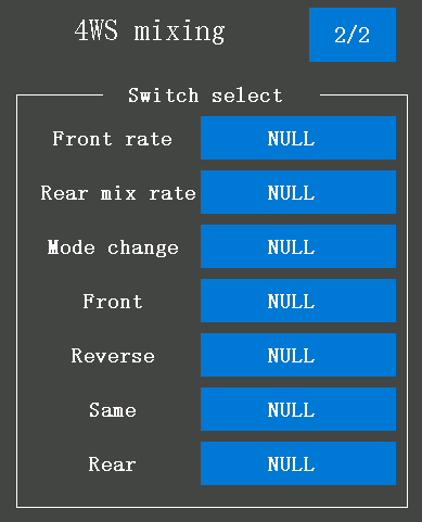
Front rate: DT1/DT2/DT3/DT4/DL1 can be set to decrease or increase the value of the front rate, select "NULL" to indicate that this function is not enabled.
Rear mix rate: DT1/DT2/DT3/DT4/DL1 can be set to decrease or increase the value of the rear mix rate, select "NULL" to indicate that this function is not enabled.
Mode change: PS1/PS2/PS3/PS4/PS5/Steering/Trigger can be selected to switch the four 4WS types (front side only, front side normal but rear side reverse phase, the front and rear keep the same phase, and rear side only).
Front/Reverse/Same/Rear:PS1/PS2/PS3/PS4/PS5/Steering/
The trigger can be selected to trigger the 4WS type, select "NULL" to indicate that this function is not enabled. For example: if set the Front switch is PS2, then press the PS2, the 4WS type will switch to the type that is front side only from other types.
2.5.5 Dual ESC mixing
This function is mixing two ESCs used with crawlers and other 4WD-type vehicles and uses channel 2 to control the rear motor and an auxiliary channel to control the front motor.
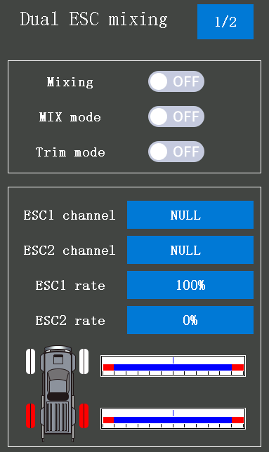
DT1/DT2/DT3/DT4/DL1 can be set to switch from front-drive only, rear-drive only, and both front and rear drive (4WD), or select one of the buttons PS1/PS2/PS3/PS4/PS5/Steering/ Trigger to trigger one of the Dual ESC types.
The trigger ratio is suggested to be set as Forward 50: Brake 50.
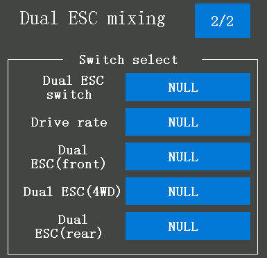
Dual ESC mixing 1/2
Mixing: The button at the right of "Mixing" is OFF, and the background color of the select box is grey, indicating that the Dual ESC mixing function is turned off. The button at the right of "Mixing" is ON, and the background color of the select box is blue, indicating that the Dual ESC mixing function is turned on.
MIX mode: The button at the right of "MIX mode" is OFF, and the background color of the select box is grey, indicating that the EXP function of channel 2 and other settings are not mixed. The button at the right of "MIX mode" is ON, and the background color of the select box is blue, indicating that the EXP function of channel 2 and other settings are mixed.
Trim mode: The button at the right of "Trim mode" is OFF, and the background color of the select box is grey, indicating that the trim of channel 2 is not mixed. The button at the right of "Trim mode" is ON, and the background color of the select box is blue, indicating that the trim of channel 2 is mixed.
ESC1 channel/ESC2 channel: set the controlled channel for ESC1/ESC2, channel1 to channel 8 can be selected.
ESC1 rate/ESC2 rate: Adjust the front and rear motor controller operation amount by clicking "+" and "-", by pressing the button "+" to adjust the rate of ESC2 and by pressing the button "-" to adjust the rate of ESC1 when both the value of ESC1 and ESC2 is 100% (the initial value). Only one of the ESC rates can lower than 100%, for example, if the ESC1 rate is 90% and the ESC2 rate is 100%, you press the button "+" will make the rate of ESC1 increase to 100% first and then decrease the rate of ESC2.
Dual ESC mixing 2/2
Click 1/2 at the top right corner to switch the setting menu from Dual ESC mixing mode, rate, and channel setting menu to the 2/2 Dual ESC mixing switch select menu.
Dual ESC switch: DT1/DT2/DT3/DT4/DL1 can be set to switch the Dual ESC (front) and the Dual ESC (rear), and select "NULL" to indicate that this function is not enabled.
Drive rate: the same function as ESC1 rate/ESC2 rate in the Dual ESC mixing1/2 menu. DT1/DT2/DT3/DT4/DL1 can be set to adjust the Dual ESC ratio, select "NULL" to indicate that this function is not enabled.
Dual ESC (front)/Dual ESC (4WD)/Dual ESC (rear): PS1/PS2/PS3/PS4/PS5/Steering/Trigger can be selected to trigger one of the Dual ESC types, select "NULL" to indicate that this function is not enabled.
As this function drives 2 separate motors simultaneously, a mutual load will be applied. Use this function carefully so that the motors are not damaged.
RadioLink will not be responsible for motor controller, motor, and other vehicle trouble due to the use of this function.
2.5.6 CPS mixing
This function can set a switch (including the steering wheel and throttle trigger) to trigger the LED to turn on or turn off. Channel 1 to channel 8 can be set as the trigger channel or operation.
If the CPS mixing function is on, and select the steering wheel or throttle trigger is the trigger switch, then the LED will turn on, turn off, or blink when steering or pushing, or pulling the trigger. The blink speed and trigger mode can be customized.
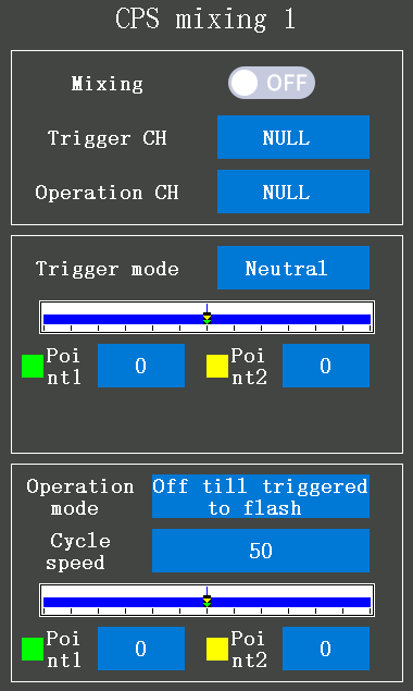
CPS mixing1/2/3/4
Mixing: The button at the right of "Mixing" is OFF, and the background color of the select box is grey, indicating that the CPS mixing function is turned off. The button at the right of "Mixing" is ON, and the background color of the select box is blue, indicating that the CPS mixing function is turned on.
Trigger CH: set the channel as the trigger channel to turn on or turn off the CPS mixing function. Channel 1 to channel 8 can be selected.
Operation CH: the channel to connect the light, channel 1 to channel 8 can be selected. When pressing the switch that controlled the light trigger channel, the light turns on or turns off. The operation channel can be set to the same channel as the trigger channel.
Trigger mode: Neutral, Left, Right, Both sides, PS switch can be selected according to the trigger switch you have set.
Point 1/2: the rudder amount to trigger the light to turn on or turn off.
Operation mode: off till triggered to flash, flash till triggered to off, off till triggered to on, and on till triggered to off can be selected.
Off till triggered to flash: the LEDs will keep off till the trigger switch reach the point value you have set that trigger the LEDs to flash. The LEDs will keep flashing until you trigger the LED to off.
Flash till triggered to off: the LEDs will keep flashing till the trigger switch reach the point value you have set that trigger the LEDs off.
Off till triggered to on: the LEDs will keep off till the trigger switch reach the point value you have set that trigger the LEDs turn on. The LEDs will keep on until you trigger the LED to off.
On till triggered to off: the LEDs will keep on till the trigger switch reach the point value you have set that trigger the LEDs to turn off.
Cycle speed: When "Operation mode" is set to "Flash", the "Cycle speed" can be set to change the LEDs' flash speed. It defaults to 50, and 1 to 100 can be selected, the smaller the value, the faster the LEDs flash.
Point 1/2: besides making the trigger switch reach the point value you have set (the point value set below the Trigger mode), points 1 and point 2 below the "Cycle speed" must be set to trigger the LEDs operation. The value of Point1 is default 0 and the value of Point2 is default 100, the absolute value of Point1 plus the absolute value of Point2 do not less than 95. The details value must depend on your LEDs.
2.5.7 Tank mixing
This function is intended for vehicles such as tanks, etc. It can be used for the pivotal turn or the ultra-pivotal brake turn by operating the steering and the throttle.
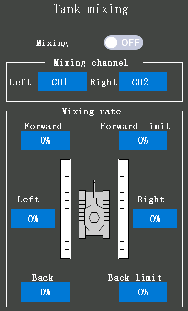
Mixing: The button at the right of "Mixing" is OFF, and the background color of the select box is grey, indicating that the Tank mixing function is turned off. The button at the right of "Mixing" is ON, and the background color of the select box is blue, indicating that the Tank mixing function is turned on.
Mixing channel: the channels select to connect the left and right motors.
Mixing rate (Forward/Back): is for forward/backward rate adjustment. The throttle channel and the steering channel operate in conjunction with each other. By operating the trigger to the high side, the car body advances at the "Forward rate" while if operate the trigger to the brake side, the car body will backward at the "Back rate".
Mixing rate (Left/Right): is for left/right side rate adjustment. The throttle channel and the steering channel operate in conjunction with each other. When operating the steering wheel to the right, the car body turns to the right at the "Right rate" pivotal turn while when operating to the left, the car will turn to the left at the "Left rate" pivotal turn.
Forward limit/Back limit: It is to limit the maximum operation amount of the throttle channel so that it does not exceed the limit by the influence of the mixing amount.
When steering and trigger are operated at the same time:
① If you manipulate the trigger to the high side and operate the steering wheel to the right, the car body will turn to the right side at the rate of "forward" and "right".
② If you manipulate the trigger to the high side and operate the steering wheel to the left, the car body will turn to the left side at the rate of "forward" and "left".
③ Operating the steering wheel while operating the trigger to the brake side will operate the same as the forward side in the reverse direction.
2.5.8 Programmable mixing
These functions allow you to apply to mix between the steering, throttle, and auxiliary channels. 8 programmable mixings can be selected. The same function is for each programmable mixing.
Program. Mixing1 1/2
Curve type: EXP curve, VTR curve, and Multiple point curve can be selected.
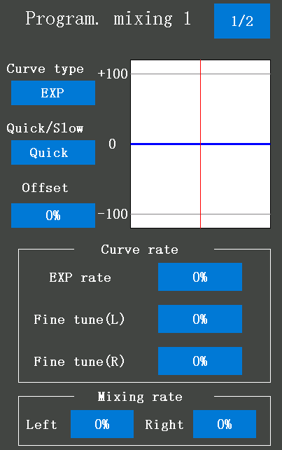
EXP curve:
Quick/Slow: is for the rate of EXP/VTR/Multiple point curve.
0% to 100% indicates the quick EXP/VTR/Multiple point rate, and -1% to -100 indicates the slow EXP/VTR/Multiple point rate. The vertical cursor line moves in conjunction with the changes in the curve rate value.
Offset: The master channel mixing center point (the point that the direction changes) can be offset.
EXP/VTR/Multiple point curve rates: The initial value is 0%, -100% to 100% can be selected.
Fine-tune (L)/(R): To set the right and left steering curves separately. The initial value is 0%, -200% to +200% can be selected.
EXP curve, VTR curve, and Multiple point curve mixing can be set from the master channel to the slave channel. For details on how to set each curve, please refer to the 2.4.1 Steering curve and 2.4.2 Throttle curve.
Mixing rate:
Left: for left, forward, or upside mixing amount adjustment. The initial value is 50%, -120% to 120% can be selected.
Right: for right, brake, or downside mixing amount adjustment. The initial value is 50%, -120% to 120% can be selected.
Program. Mixing1 2/2
Click 1/2 at the top right corner to switch the first programmable mixing setting page to the second programmable mixing setting page.

Switch select: PS1 /PS2 /PS3 /PS4 /PS5 /Steering /Trigger can be selected to turn on or turn off the programmable mixing function, select "NULL" to indicate that this function is not enabled.
Mixing: The button at the right of "Mixing" is OFF, and the background color of the select box is grey, indicating that the Program. mixing1 function is turned off. The button at the right of "Mixing" is ON, and the background color of the select box is blue, indicating that the Program. mixing1 function is turned on.
MIX mode: The button at the right of "MIX mode" is OFF, and the background color of the select box is grey, indicating that the EXP function of channel 2 and other settings are not mixed. The button at the right of "MIX mode" is ON, and the background color of the select box is blue, indicating that the EXP function of channel 2 and other settings are mixed.
Trim mode: The button at the right of "Trim mode" is OFF, and the background color of the select box is grey, indicating that the trim of channel 2 is not mixed. The button at the right of "Trim mode" is ON, and the background color of the select box is blue, indicating that the trim of channel 2 is mixed. When the steering or throttle channel is the master channel, trim data can be added.
Mixing channel: is for setting the master and slave channels.
Master: channel that applies to mix. Channel 1 to channel 8 can be selected as the master channel.
Slave: channel 1 to channel 8 can be selected as the slave channel. The movement of the master channel side will include the movement of the slave channel side.
Click 2/2 at the top right corner to back to the first programmable mixing setting page from the second programmable mixing setting page.
2.5.9 Tilt mixing
Tilt mixing uses an outboard engine and applies bidirectional mixing from rudder to flap and from the flap to rudder so that with a boat, rudder operation and tilt mixing operation can be performed in 2 servos.
Tilt mixing can be performed by rudder operation, the steering wheel, and the flap channel.
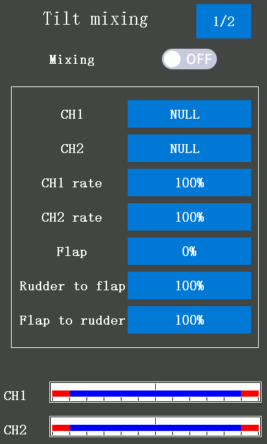
Mixing: The button at the right of "Mixing" is OFF, and the background color of the select box is grey, indicating that the Tilt mixing function is turned off. The button at the right of "Mixing" is ON, and the background color of the select box is blue, indicating that the Tilt mixing function is turned on.
CH1: channel 1 to channel 8 can be selected to control the tilt steering.
CH2: channel 1 to channel 8 can be selected to control the tilt flap.
CH1 rate/CH2 rate: for the mixing amount rate. The initial value is 100%, -120% to 120% can be selected. If both CH1 and CH2 rates set positive or negative values, the tilt steering, and tilt flap will keep moving in the same direction, while if the CH1 rate set a positive value and the CH2 rate set a negative value, the tilt steering and tilt flap will move the opposite direction.
Flap: flap rate check and adjustment. The initial value is 0%, -100% to 100% can be selected. The flap value set depends on the angle of the two flaps (steering and flap). If you want to set the steering and flap separately, please set the value of the Rudder to flap or Flap to the rudder.
Rudder to flap: Rudder to Flap mixing amount can be adjusted individually. The initial value is 100%, -100% to 100% can be selected. -1% to -100% indicate the operation in the same direction as steering. 0% to 100% indicate the opposite direction of steering.
Flap to rudder: Flap to Rudder mixing amount can be adjusted individually. The initial value is -100%, -100% to 100% can be selected. 0% to 100% indicates the operation in the same direction as an auxiliary channel. -1% to -100% indicate the opposite direction of the auxiliary channel.
The steering endpoint function, curve function, speed function, or D/R function setup also affects flap channel operation. However, even if set, the steering reverse function setup does not reverse the flap channel.
Tilt Mixing 2/2
Click 1/2 at the top right corner to switch the first Tilt mixing setting page to the second Tilt mixing setting page.
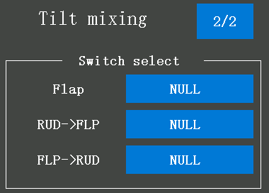
Flap: DT1/DT2/DT3/DT4/DL1 can be selected to increase or decrease the Flap value. Press the button which you have selected to increase or decrease the value of the flap, and the mixing amount from rudder to flap and the mixing amount from the flap to rudder will be adjusted.
RUD->FLP: DT1/DT2/DT3/DT4/DL1 can be selected to adjust the mixing amount from rudder to flap.
FLP->RUD: DT1/DT2/DT3/DT4/DL1 can be selected to adjust the mixing amount from flap to rudder.
2.6 Tools menu
2.6.1 Screenshot setting
Take screenshots of the interface of the transmitter, convenient for users to obtain and share the contents of the transmitters.
Switch select: The buttons PS1, PS2, PS3, PS4, or PS5 can be set to trigger the screenshot function.
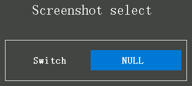
How to take a screenshot: Press the switch that you have set in the Screenshot select menu, wait about three to five seconds, and "Snapshot successfully!" displayed on the top of the screen indicates screenshot successful. If the "Voice mode" has selected "All" in the Sound menu, the word "Snapshot successfully!" will display with voice broadcast. The screenshot files will save to the folder named "screenshot" on the SD card. The first screenshot picture will default named "Screenshot_0.bmp", and the number of the file name will increase by one for each additional picture.
Screenshots preview: it is not supported to preview screenshots directly in the transmitter. If you want to preview the screenshots, you can connect the transmitter and the computer with a Type-C USB cable, and then preview the screenshots on the computer. Or pull out the SD card and insert it into the card reader, and then insert the card reader into the USB port of the computer to preview the screenshots. (As shown on the right)
Screenshots preview steps:
1) connect the transmitter and the computer with a Type-C USB cable, and then press the button PS1 and press the power button at the same time to turn on the transmitter, a tooltip will pop out, if the yellow select box at USB MODE, press the power button to make the USB connection. A flash drive will pop out when connecting success.
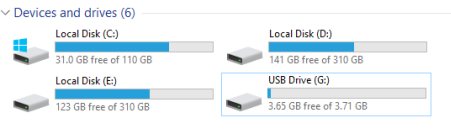
2) click the "screenshot" folder in the flash drive to preview the screenshots
3) click the picture you want to preview
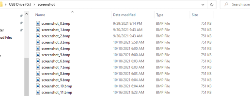
Attention:
- Do not pull or insert the SD card during taking screenshots.
- It is not supported to rename the screenshots or delete the screenshots directly in the transmitter.
- The charging USB cable without a data transmission function cannot be used to make your transmitter and the computer connects success, please use a USB data cable to connect.
- All files on the SD card only support English, not other languages. If you rename it to another language, the file name will be garbled when you going to preview the screenshots files in the transmitter.
- If the SD card is pulled out and the contents have been modified, you need to insert the SD card into the transmitter and then restart the transmitter to see the modified content in the SD card.
2.6.2 Timer
In the timer setup menu, the alarm time, timer mode, alarm sound type, the switch to trigger the timer, the switch for resetting the timer, vibrator type, and throttle trigger to a timer can be set.
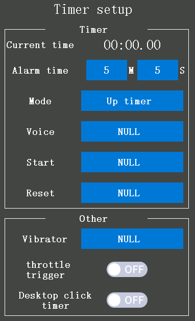
Alarm time: the time to trigger the alarm. When the current time reaches the alarm time, the transmitter will alarm. It defaults will alarm at 5 minutes and 0 seconds, which can be customized. The value on the left of M represents minutes, and the value on the left of S represents seconds, which can be customized.
Attention: M indicates Minute and S indicates Seconds
Mode: the mode for the timer, "Up timer" and "Fuel down timer" can be selected, click the blue select box at the right of Mode to set.
Up timer: starts at 0 and displays the elapsed time up to 99 minutes 59 seconds.
Fuel down timer: starts from the chosen time, display time remaining, and stops at 0.
Voice:
Type 1: When the timing time reaches the alarm time you have set, the transmitter will vibrate for 2 seconds.
Type 2: If the timer function is turned on, there is a sound reminder every second. And, when the timing time reaches the alarm time you have set, the transmitter will vibrate for 2 seconds.
Start: the switch to trigger the timer, PS1, PS2, PS3, PS4, PS5, Steering, and Trigger can be selected. If the set Steering switch or Trigger switch is the start switch, rotate the SS or push the TS switch to the end to start the timer function.
Reset: the reset switch is set for pause timing and reset timer time. If the timer has started, press the reset button once to pause the timer, and press the timer again to reset the timer time, that is, to return to 00:00.00.
Vibrator:
"NULL": indicate that the vibrate function is not enabled.
Type 1: the transmitter will vibrate for about 1 second at the end of the timer.
Type 2: If the timer function is turned on, the transmitter will vibrate every second. And, the transmitter will vibrate for about 1 second at the end of the timer.
Throttle trigger: the function defaults turn off.
The button at the bottom of the screen is OFF, and the background color of the select box is grey, indicating that no matter the pulls or pushes the trigger will not turn on the timer function.
The button at the bottom of the screen is ON, and the background color of the select box is blue, indicating that when pulling or pushing the trigger will turn on the timer function.
Attention:If the timer start function selects the trigger as the trigger button and the throttle trigger function has turned on, the throttle trigger function will be used first.
Desktop click timer: If it is turned on, tap once to start/stop/reset timing on the home page. If it is turned off, none of the feedback will receive no matter how many taps you give on the home page.
2.6.3 Roll out chart
This function is designed for pan cars. The rollout chart can be calculated from input values for the number of teeth of the spur gear and pinion gear, and the tire diameter and displayed as a table.
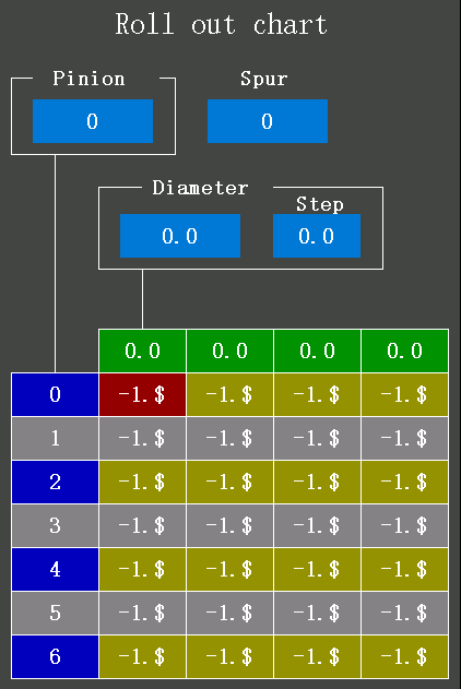
Pinion: Tap the blue select box under Pinion to select the value of the pinion gear, click "-" can decrease the value, and click "+" can increase the value, 10 to 60 can be selected.
Spur: Tap the blue select box under Spur to select the value of the teeth of spur gear, click "-" can decrease the value, and click "+" can increase the value, 50 to 130 can be selected.
Diameter: Tap the blue select box under Diameter to select the value of the tire diameter, click "-" can decrease the value, and click "+" can increase the value, 40.0 to 100.0 can be selected.
Step: Tap the blue select box under Step to set the step of input numerical value of tire diameter amount, click "-" can decrease the value, and click "+" can increase the value, 0.1mm to 1.0mm can be selected.
2.6.4 Gear ratio chart
The Gear Ratio Chart can be calculated from input values for the number of teeth of the spur gear and pinion gear, and the second gear ratio, and displayed as a table.
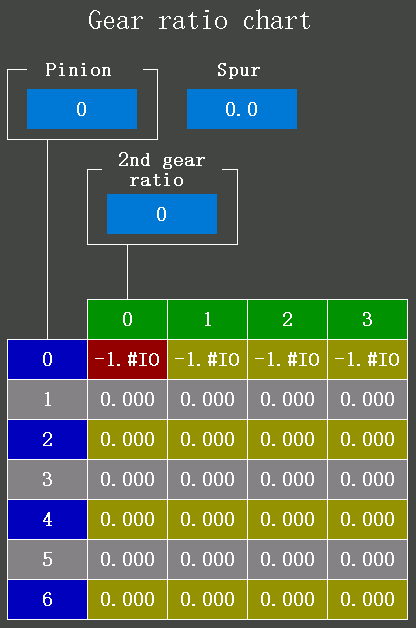
Pinion: Tap the blue select box under Pinion to select the value of the pinion gear, click "-" can decrease the value, and click "+" can increase the value, 10 to 60 can be selected.
Spur: Tap the blue select box under Spur to select the value of the teeth of spur gear, click "-" can decrease the value, and click "+" can increase the value, 0.0 to 100.0 can be selected.
2nd gear ratio: Tap the blue select box under the 2nd gear ratio to select the value of the second gear ratio, click "-" can decrease the value, and click "+" can increase the value, 50 to 130 can be selected.
2.7 Model select
200 models' data can be saved in the transmitter RC8X. The name of every model can be renamed, and the factory settings of every model can be reset in this menu. Data can be copied and pasted between every two models. Click the model that needs to be set, and the following settings will appear on the screen.
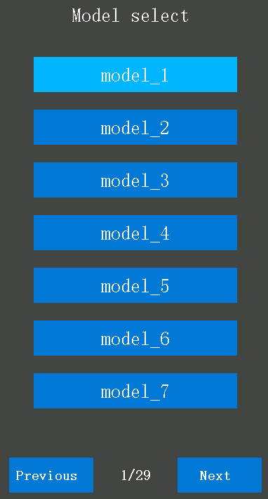
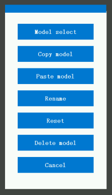
2.7.1 Model select
Model memory selection. You can choose from model 1 to model 200. Tap the mark "Previous" or "Next" at the bottom of the screen to switch the page. When you click the button "Model select", a question "Are you sure to select the model: model_1?" will pop out, click "Confirm" to select the model_1 as the current model, and the model's name can be renamed. If you do not want to select the model_1, click "Cancel" and then choose the model's name you want. The model's name which you have selected will display on the top of the screen.
2.7.2 Copy model/Paste model
The contents of the model memory can be copied to another model memory. The copy model function and paste model function must be used at the same time to finish the model memory copy. For example, if you want to copy the model_1 data to the model_3, you need to click the button "model_1", click "Copy model", and click "Confirm" when the question "Are you sure to copy the model? model_1" have popped out, and then click the button "model_3", click "Paste model", click "Confirm" when the question "Copy model_1 to model_3?" have to pop out.
Attention: when you click "Paste model", a question "Copy data error. Please copy again!" means you have to copy data, you have to copy data from another model, and then paste it to the model you need. Copy model and paste model will not succeed for one model.
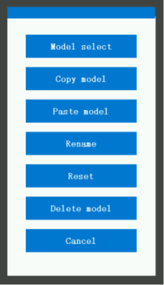
2.7.3 Rename model
All the models' names can be renamed. For example, if you want to rename the model_1, you need to click the button "model_1", click "Rename", a keyboard will pop out, click "Delete" to delete the original name, tap "←" or "→" to move the cursor and select the character of the model name you want to set or change, click "Confirm" at the bottom of the screen to save the setting.
2.7.4 Reset model
All the models' data can be reset to the factory setting. For example, if you want to reset the memory of model_1, you need to click the button "model_1", click "Reset", and click "Confirm" when the question "Are you sure to reset the model? model_1" have pop out.
2.7.5 Delete model
Select the model to be deleted. Click Delete Model, and then confirm to delete the model.
2.7.6 Model data copy
Model data and system settings of RC8X can be saved and then pasted into another RC8X. For detailed steps, please refer to the link below:
https://www.radiolink.com.cn/save_and_paste_model_data_to_another_rc8x
2.8 SD Card Folder
Users can customize and change the content of the files. For example, they can add or delete firmware, modify the icon of the transmitter, and modify the prompt sound.
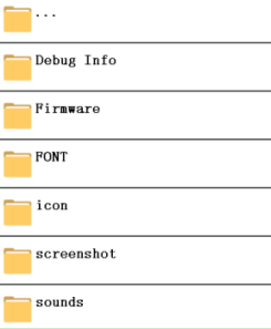
…: Click "…" to return to the previous directory, and click all the folders under this menu to enter the directory. Tap the mark "Previous" or "Next" at the bottom of the screen to switch the page.
2.8.1 SD Card Folder Name Introduction
Folder Name | Function | Folder Name | Function | |
Debug Info | Debug information | ESC | Icon of ESC | |
Firmware | Firmware of RC8X | Desktop | Icon of desktop | |
FONT | Font of RC8X | Cache file | Cache file | |
SIF | font library, the RC8X will cannot power on if delete the SIF folder | Battery | Battery | |
Icon | All the Icons in RC8X | 4WS | 4 Wheel Steering | |
Signal | Icon of signal | Screenshot | Screenshot | |
setting | Icon of setting | Sounds | Sounds of RC8X | |
receiver | Icon of receiver | SYSTEM | System sounds of RC8X | |
file | Icon of files | USER | Sounds customized by users |
2.8.2 SD Card Files Copy Methods
1) Copy the files with a card reader
① power off the RC8X, remove the SD card from RC8X, insert the SD card into a card reader, and connect the card reader to the USB port of the computer.

② a flash drive will pop out when you connect the SD card to the computer, then all the files can be customized as you need.
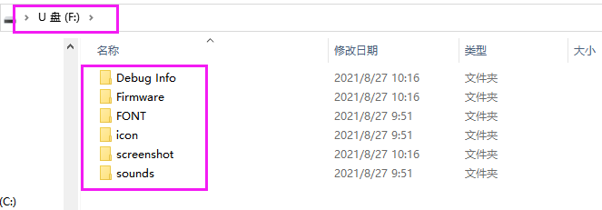
③ copy, delete, or customize the files you want, and then insert the SD card back into your transmitter RC8X.
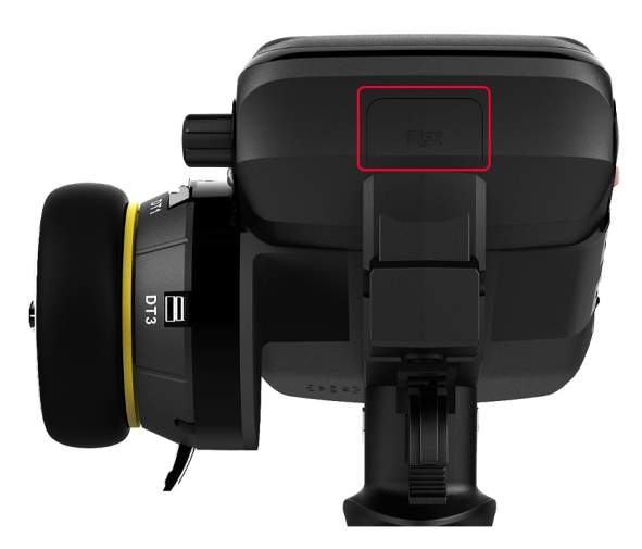
2)Copy the files with a USB cable (copy a firmware as an example)
Introduction about the nomenclatures on the update setting menu
SD Size: The RC8X comes with a 32G memory card as standard, if you want to replace a larger memory card when the RC8X is connected to a computer, the read speed will be slower, it will take about 2 minutes.
SD Residue Size: the remaining capacity of the SD card.
DL1_A: UP/DL1-B: DOWN: make the yellow select box up or down by pressing the button DL1 to select the function you need.
PS3: press the button PS3 to back to the previous setting menu.
HOME: at the update mode, by pressing the power button to confirm the setting/select.
USB MODE: press the power button and select the "USB MODE" to make the SD card of RC8X connect to the computer
Update the latest: update the latest firmware that saved in the SD card of RC8X
Upgrade the specified: update the specified firmware that saved in the SD card of RC8X
Power off: exit the update setting menu and the RC8X will turn off at the same time.
The setting steps are as below:
1)keep the RC8X off,
2)use a USB cable (type-c) to connect the RC8X to the computer.

3)Push DT1 and DT2 TRIM buttons to the middle position, and long press the power button at the same time to enter into the data copy and upgrade mode. The following four options will appear on the screen, and "USB MODE" is selected by default.
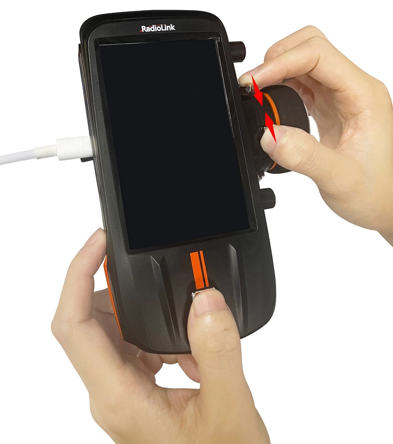
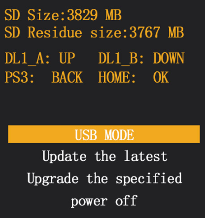
4) Short press the "power button" to enter the USB mode. The computer usually displays two removable disks. RC8X-EXT refers to the SD card, and RC8X-INH refers to the remote control. Copy the firmware to the RC8X-EXT disk.
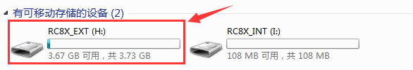
Note: The firmware downloaded from the official website is usually a compressed file. After downloading it to your computer, you need to unzip it first. After decompression, copy the three files (including Firmware, FONT, and icon) in the folder to the RC8X-EXT disk.
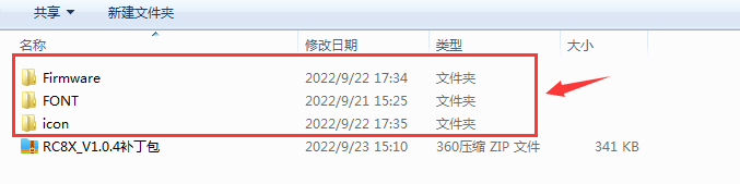
Note: During the copying process, when it pops the reminder, please choose "copy and replace" and then click "YES".
5)After the firmware copy is complete, press the PS3 button to return to the previous menu. Then turn the DL1 knob to turn the yellow background cursor to "power off", and then short press the "power button" to exit the upgrade mode.
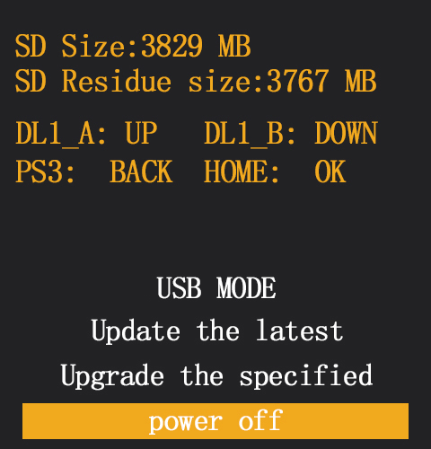
2.8.3 Note for SD card content modification
1) Do not modify, delete, or preview files directly in the RC8X. A type-c USB cable is needed to connect the RC8X and the computer to view and modify the files on the computer.
2) All filenames on the SD card only support English. If you change the filename to other languages, the filename will display garbled characters.
3) If the SD card is pulled out and then inserted into the RC8X, the RC8X needs to be restarted to read the modified contents in the SD card.
2.9 Modifying for Left-hand Use
The wheel section left and right installation direction can be reversed.
The wheel is default at the right of RC8X, users can reinstall it with a Phillips screwdriver.
Here is the tutorial:
The following operation takes the right-hand use modified to the left-hand use as an example:
2.9.1 Remove the Wheel
1) Use a Phillips screwdriver to remove the two mounting screws (HA3.0*12mm screws) on the steering wheel adapter.
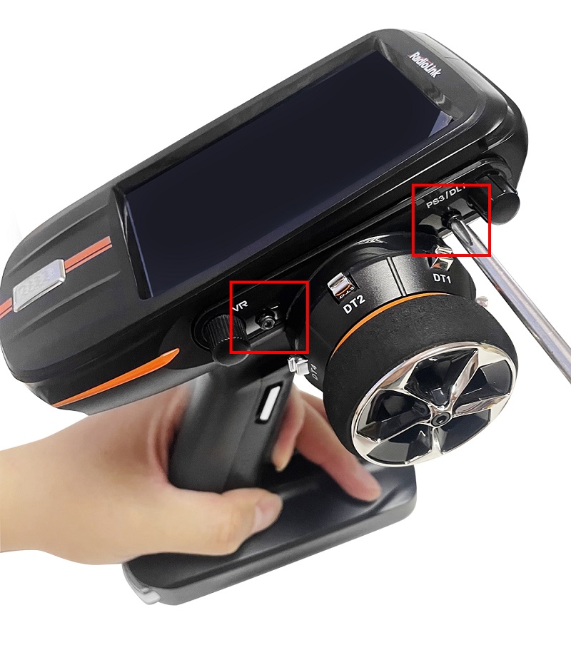
2) Gently pull off the steering wheel and do not pull the cable excessively. Since the steering wheel has been locked by the plastic sheet, please do not pull it out directly.
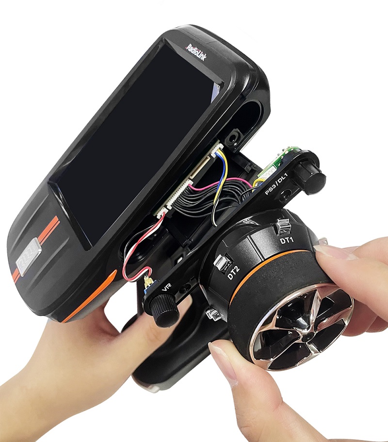
3) Remove the three cables from the PCB board of RC8X, press the socket on the RC8X
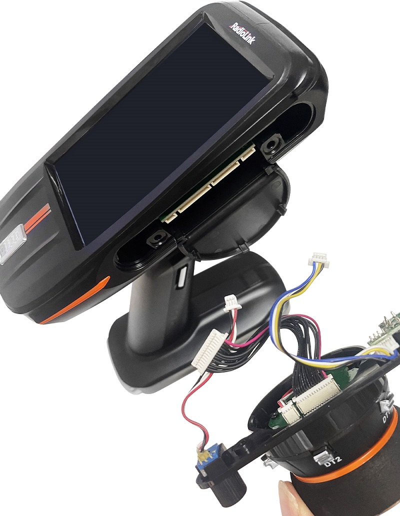
4) Pull out the plastic plate under the wheel.
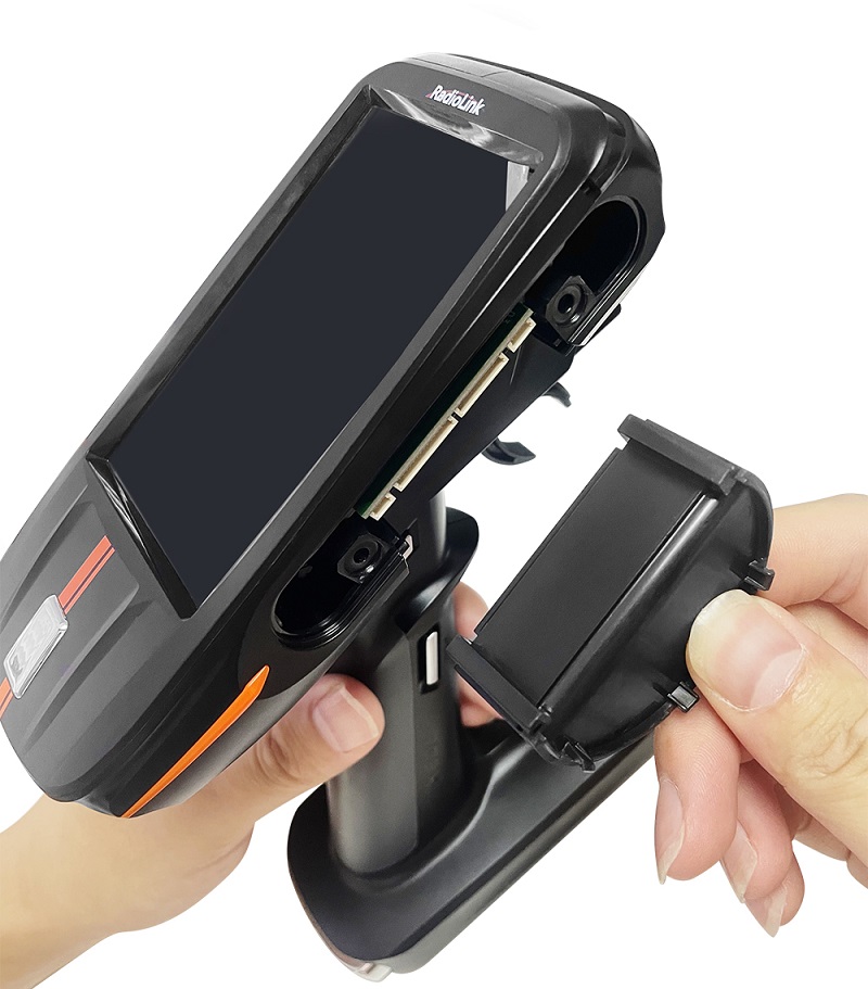
2.9.2 Remove the Wheel Installation Port Cover
1) Use the Phillips screwdriver to remove the two mounting screws (HA3.0*12mm screws) on the left wheel installation port cover.
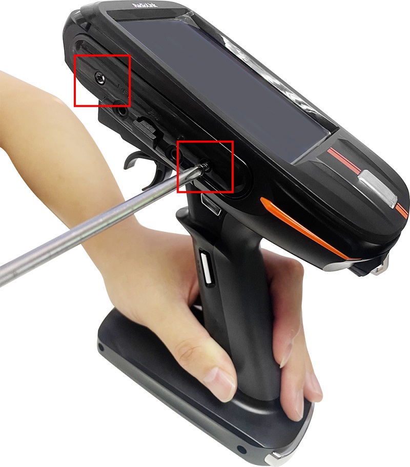
2) Gently pull off the left wheel installation port cover.

3) Gently pull out the USB port motherboard.
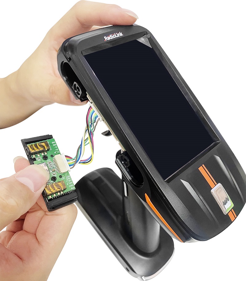
4) Remove the cable from the RC8X PCB board.
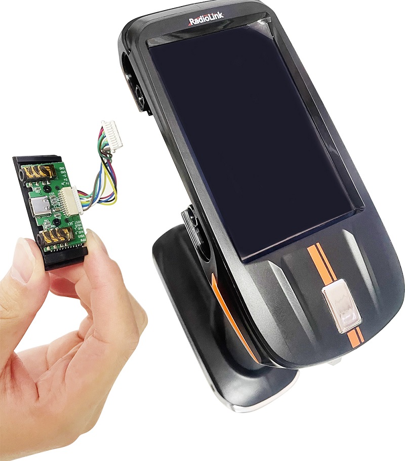
2.9.3 Install Wheel
1. Insert the 14-pin plug, 3-pin plug, and 4-pin plug on the steering wheel into the corresponding sockets in the middle of the PCB motherboard on the left side of the RC8X.
2. Insert the plastic steering mounting plate. When inserting part of it, gently insert the extra part of the 3 connector wires into the interlayer of the RC8X PCB board.
Note: Do not block the installation position of the two screws when jamming the cables. Otherwise, installing the wheel will crush the cable.
3. Align the steering wheel installation screw mounting position and the screw mounting position of RC8X.
4. Tighten the two screws.
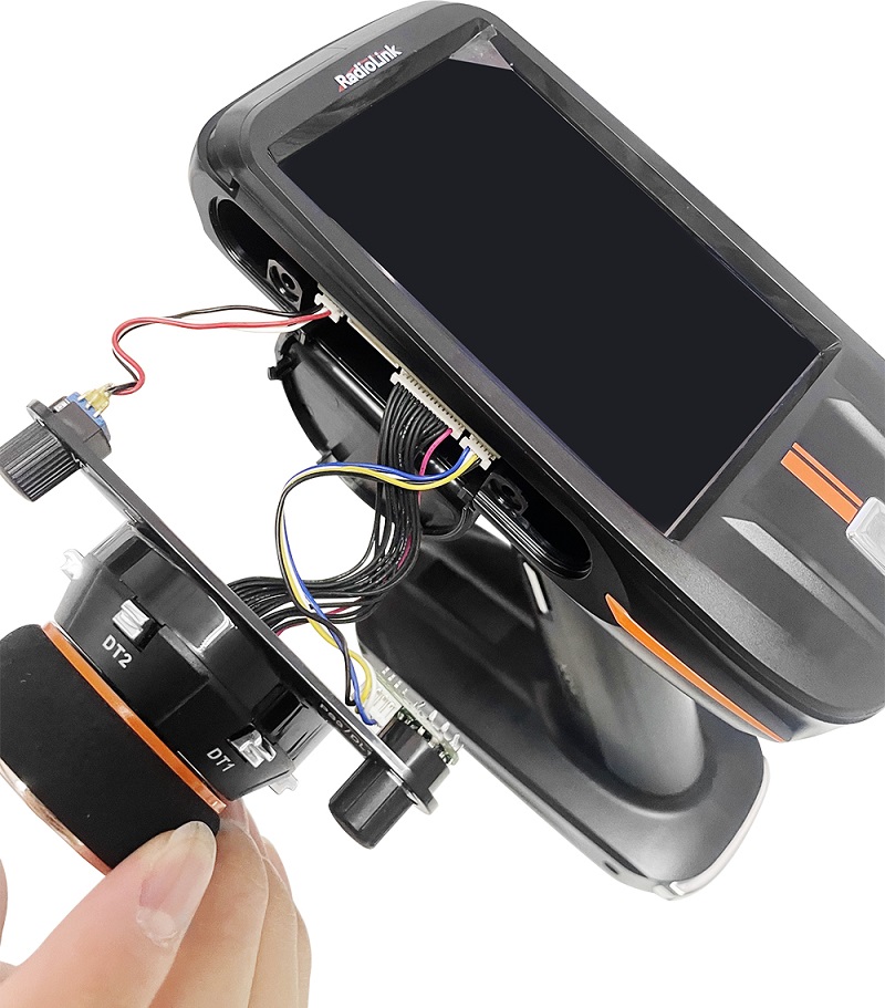
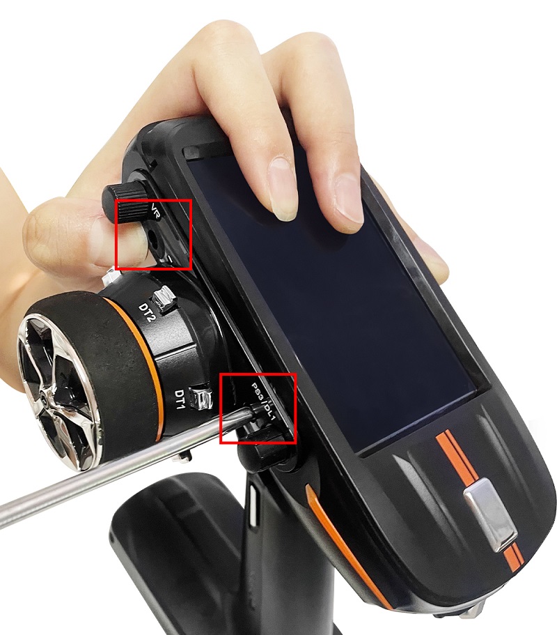
2.9.4 Install the Wheel Installation Port Cover
- Insert the 11-pin plug on the plate into the corresponding port of the PCB motherboard on the right side of the RC8X.
- Gently insert the extra part of the wire into the interlayer of the RC8X PCB board.
- Insert the black plastic steering mounting plate into the corresponding wheel installation port.
- Cover the black plastic USB port plate, and tighten the two screws.
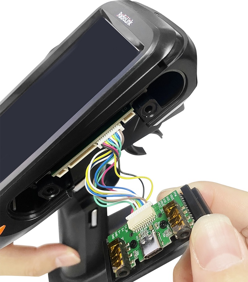
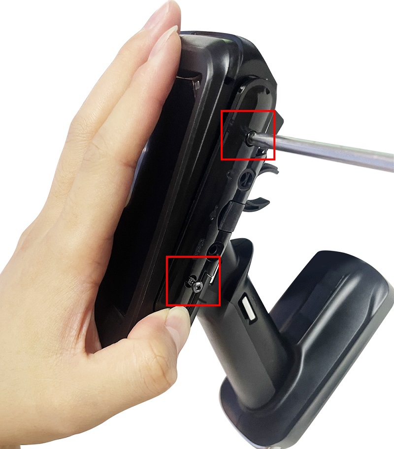
The picture is as follows after modifying the wheel from the right to the right:
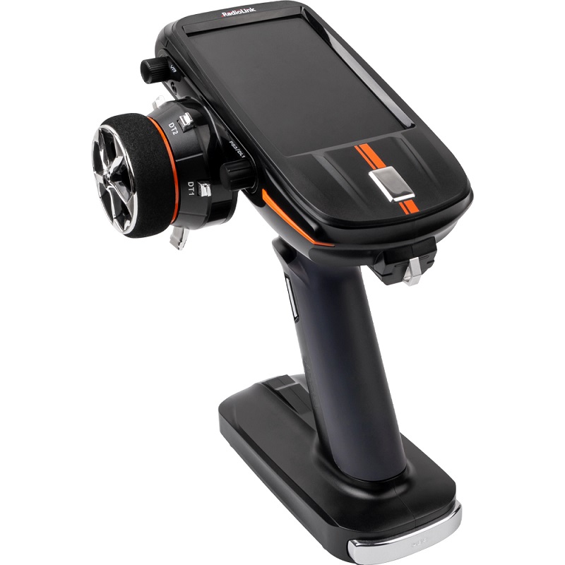
2.10 Wheel or Trigger Mechanical Adjustment
The wheel or trigger of RC8X can be adjusted mechanically according to your needs.
2.10.1 Trigger brake lever adjustment
Make this adjustment when you want to decrease the stroke of the brake side of the throttle trigger for an operation feel.
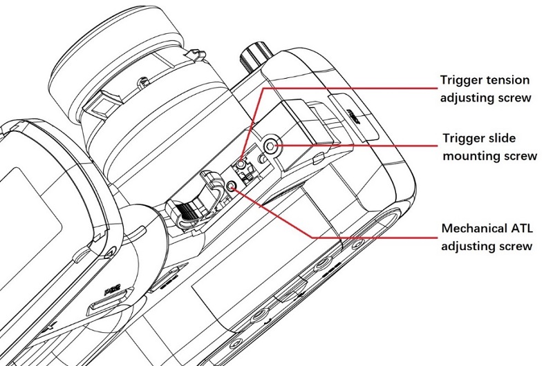
Adjustment steps: Using a 1.5mm hex wrench, loosen the trigger tension screw (1.5mm) by turning it slightly counterclockwise.
Note: Adjust the stroke while observing the screw. Once the mechanical stroke of the throttle is changed, please re-calibrate the throttle trigger. The calibration method refers to 2.1.10 "Calibration". Due to this change, it is also necessary to adjust the throttle rudder in most cases The stroke of the machine can be set through "EPA".
2.10.2 Trigger tension screw adjustment
Adjust the trigger tension screw when you want to change the tension of the trigger spring.
Adjustment steps: Using a 1.5mm hex wrench, loosen the trigger tension screw (1.5mm) by turning it slightly counterclockwise. If the trigger tension screw is turned too much, the screw may fall out. When the adjusting screw is turned clockwise, the spring tension increases.
2.10.3 Trigger slide adjustment
The throttle trigger position can be moved forward and backward by loosening or tightening the screw.
Adjustment steps: Using a 2.0mm hex wrench, loosen the trigger slide mounting screw (2.0mm) by turning it slightly counterclockwise. If the trigger slide screw is turned too much, the screw may fall out.
2.10.4 Wheel tension screw adjustment
Adjust the wheel tension screw when you want to change the tension of the wheel spring.
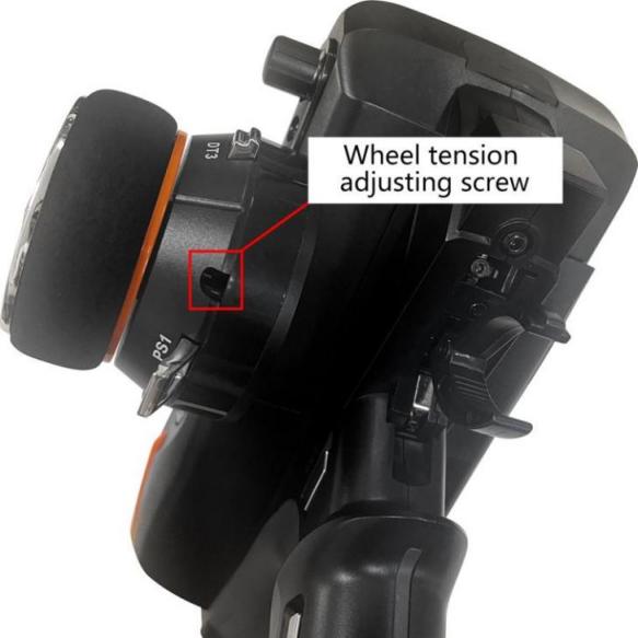
Adjustment steps: Using a 1.5mm hex wrench, loosen the trigger tension screw (1.5mm) by turning it slightly counterclockwise. If the trigger tension screw is turned too much, the screw may fall out.
2.11 Firmware Update
RC8X will keep updating the firmware to add new functions. Please pay attention to our website www.radiolink.com to get the latest firmware.
Before updating, the latest firmware must be copied to the micro-SD card of your RC8X.
RC8X firmware update tutorial:
2.11.1 Methods for Firmware Copy
Please refer to: 2.8.2 SD Card Files Copy Methods
2.11.2 Methods for Firmware Upgrade
There are two ways for RC8X to update the software in total.
1) "Update the latest" Mode
If there are several firmware saved in the microSD card, RC8X will recognize the latest firmware automatically and then update it in this update mode.
① Enter the update mode setting menu
>power on the RC8X but do not turn it on.
>Push DT1 and DT2 TRIM buttons to the middle position, and long press the power button at the same time to enter into the data copy and upgrade mode. The computer will pop out that a USB drive is inserted.
② select update mode
> The following four options will appear on the screen, and "USB MODE" is selected by default.
> Turn the DL1 knob to turn the yellow background cursor to "Update the latest"
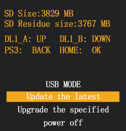
③ upgrade the latest firmware
> short press the power button into the "Update the latest" mode, and short press the power button again to upgrade.
> "being updated" pops out at the bottom of the screen means the firmware is updating.
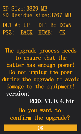
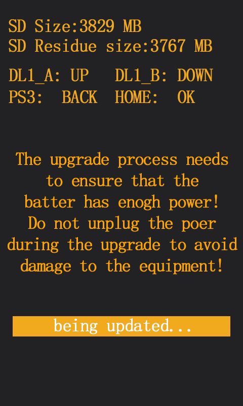
④ "update successfully" pops out at the bottom of the screen means the firmware upgrade is successful.
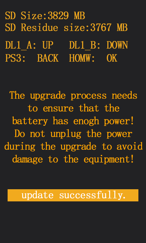
⑤ exit the update mode
> Press the PS3 button to return to the previous menu.
> Turn the DL1 knob to turn the yellow background cursor to "power off".
> Short press the power button to exit the upgrade mode.
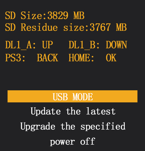
Attention: if "firmware reads fail!" pop out at the bottom of the screen means the transmitter RC8X has not found the firmware from the microSD card, please copy the latest firmware to the microSD card first, and then reupdate following the steps above.
2) "Upgrade the specified" Mode
If you have copied the upgrade firmware to the micro SD card, but have modified the firmware name, then the "Upgrade the specified" update mode is suggested.
① Enter the update mode setting menu
>power on the RC8X but do not turn it on.
>Push DT1 and DT2 TRIM buttons to the middle position, and long press the power button at the same time to enter into the upgrade mode. The computer will pop out that a USB drive is inserted.
② select update mode
> The following four options will appear on the screen, and "USB MODE" is selected by default.
> Turn the DL1 knob to turn the yellow background cursor to "Update the specified"
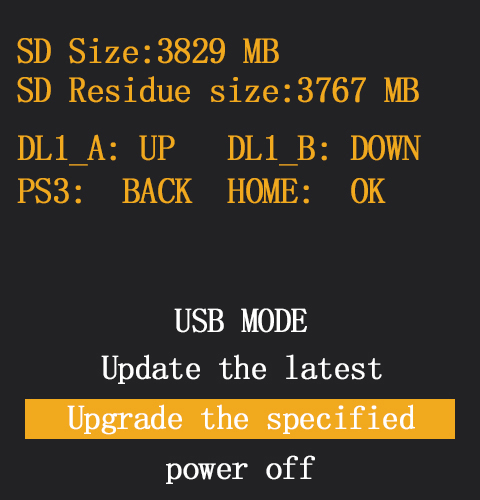
③ upgrade the specified firmware
> short press the power button into the "Update the specified" mode, and short press the power button again to upgrade.
> "being updated" pops out at the bottom of the screen means the firmware is updating.'
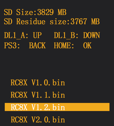
④ "update successfully" pops out at the bottom of the screen means the firmware upgrade is successful.
⑤ exit the update mode
> Press the PS3 button to return to the previous menu.
> Turn the DL1 knob to turn the yellow background cursor to "power off".
> Short press the power button to exit the upgrade mode.
2.12 Customized Voice Production
Not only is the voice package that comes with RC8X but also the customized voice is available for the user to set the Audio source. Users can make custom prompt voice production through text-to-speech software, and then copy the voice file to the transmitter, where they can choose their own voice. It is specially designed for users in non-English language countries.
- After recording the voice file, modify the format of the voice file to ensure that the format of the voice file meets the following 4 conditions:
- WAV format
- Sampling rate 16KHZ or 32KHZ
- Mono
- Bit depth 16 bits
The following steps show how to convert the format of an audio file to make it meet the above 4 conditions. Take Adobe Audition voice software as an example.
(1) Import the voice file whose format needs to be modified into Adobe Audition software, and then click File - Save As.
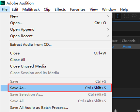
(2) Modify the voice file format to ensure that the format conforms to WAV format, Sample rate 16KHZ or 32KHZ, monophonic, and 16 bits depth. After selecting the save location, click OK, and a qualified voice file will be generated.
Note: Don't tick "Include markers and other metadata".
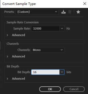
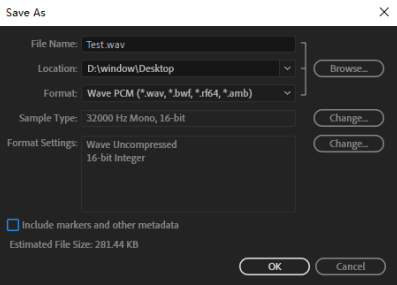
2. Copy the voice file to RC8X.
Please refer to 2.8.2 SD Card Files Copy Methods to copy the modified audio to RC8X_EXT(H) -sounds-USER. (The file name is "Test")
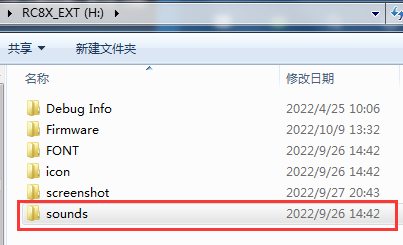
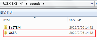
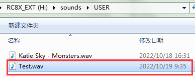
3. Select your own voice prompts on RC8X. When setting a Trim/Dial tone and Switch sound, select Customized voice, and then the corresponding audio file. (The file name is "Test")
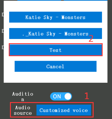
Thanks
Thank you so much for choosing RadioLink 2.4 GHz 8 channels transmitter – RC8X.
To fully enjoy the benefits of this product and ensure safety, please read the manual carefully and set up the device as instructed steps. If any problems are found during the operation process, either way, the listed below can be used as online tech support.
- Send emails to after_service@radioLink.com.cn and we will answer your question as the earliest.
- Send a private message to us on our Facebook page or leave comments on our YouTube page.
- If the product is purchased from the local distributor, you can also ask them for support and repair as preferred.
A 32G SD card will be packed with RC8X, it can be used for transmitter upgrade or save the font, icon, screenshot, sound, and other customized files you have designed for your RC8X.
All manuals and firmware are available on RadioLink official website www.radiolink.com and more tutorials will be uploaded. Follow our Facebook and YouTube homepage to stay tuned for our latest news.