
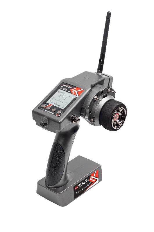
RC6GS V2
Digital 6-Channel Proportional RC System
Instruction Manual
 Adaptable to RC Cars/Boats/Robot
CE FCC RoHS
* Please be kindly noted that this manual will be updated regularly and please visit RadioLink official website to download the latest version.
This product is not a toy and is NOT suitable for children under the age of 14. Adults should keep the product out of the reach of children and exercise caution when operating this product in the presence of children. Never operate your model during adverse weather conditions. Water or moisture may enter the transmitter inside through gaps in the antenna or joystick and cause model instability, even out of control. If running in the wet weather(such as game) is inevitable, always use plastic bags or waterproof cloth to cover the transmitter.
This device complies with part 15 of the FCC Rules. Operation is subject to the following two conditions: (1) This device may not cause harmful interference, and (2) This device must accept any interference received, including interference that may cause undesired operation.
Any Changes or modifications not expressly approved by the party responsible for compliance could void the user's authority to operate the equipment.
Never operate your model during adverse weather conditions. Poor visibility can cause disorientation and loss of control of your model.
Never use this product in a crowd and illegal area.
Always ensure the trim levers at 0 and battery properly charged before connecting the receiver.
Always check all servos and their connections prior to each run.
Always be sure about turning off the receiver before the transmitter.
Size: 213 *117 * 115.5mm (6.39”*3.51”*3.46”)
Weight: 342g(12oz)
Channel: 6CH
Antenna Length: 106mm(4.17")
Control Range: 600m(1968.5ft)
Operating Current: 80-120mA
Operating Voltage: 4.8-15V
(6pcs of AA battery or 2S-4S LiPo battery)
RF Power: <20dbm
Frequency: 2.4Ghz ISM Band(2400.0MHz--2483.5MHz)
Modulation Mode: GFSK
Channel resolution: 4096, the regular jitter is 0.5us
Spread Spectrum: FHSS 67 Channels Pseudo Random Frequency Sequence Hopping
LCD Screen: 128*64 Resolution, LCD Back Light
Low Voltage Alarm: Yes (can be customized on 2S-4S battery)
Adaptable Models: Fishing boats, Robots Vehicles(Crawlers/Tanks/Truck)
CompatibleReceiver:R7FG, R6FG,R6F, R8EF, R8F, R4FGM,R4F
Battery Tray Dimension: 89*59*18mm (3.5”*2.32”*0.71)
Model Memory: 10
 Display on LCD Screen
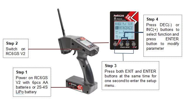
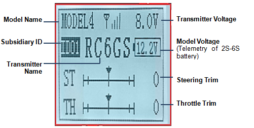 When powering on RC6GS V2, Model Name, Subsidiary ID, Transmitter Name, Battery Voltage, Model Battery Voltage, Steering Trim and Throttle Trim will be displayed on LCD screen.
Note The Subsidiary ID won’t display until the function is activated in the menu ID SEED. The telemetry function of model battery voltage canonly be realized with R7FG/R8F.
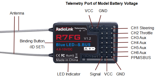
Receiver R7FG (Standard Pack)
Receiver packed with RC6GS V2 is R7FG, 2.4GHz 7 channels, gyro integrated and high voltage servo supported.
Binding
Put the transmitter and the receiver close to each other (about 50 centimeters) and power both on. 2. Switch on the transmitter and the led on R7FG will start flashing slowly.
3. There is a black binding button(ID SET) on the side of receiver. Press the button for more than 1 second and release, the led will flash quickly, meaning binding process is ongoing.
4. When the led stops flashing and is always on, binding is complete and there will be a signal tower shown on top of the LCD screen of the transmitter. If not succeed, the led will keep flashing slowly to notify, repeat the above steps.
Note NO gyro by default as factory setting. Since integrated gyro in R7FGwill self-check, it is very important to remain R7FG still when powering it on. GREEN LED (always on) indicates normal working mode while GREEN+RED LEDs (always on) indicate gyro working mode. When RED is off means NO gyro. If binding is not successful, the green led will keep flashing to notify.
Note of receiver usage
Keep the two antennas at a 90-degree angle (as shown on right):
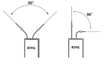 Big models may contain metal parts that influence signal emission. In this case, antennas should be positioned at both sides of the model to ensure the best signal status in all circumstances.
Antennas should be kept away from metal conductor and carbon fiber at least half inch away and no over bending.
Keep antennas away from motor, ESC or other possible interference sources.
Sponge or foam material is advised to use to prevent vibration when installing receiver.
Receiver contains some electronic components of high-precision. Be careful to avoid strong vibration and high temperature.
Special vibration-proof material for R/C like foam or rubber cloth is used to pack to protect receiver. Keeping the receiver in a well-sealed plastic bag can avoid humidity and dust, which would possibly make the receiver out of control.
When all the above steps are complete, please turn off the transmitter and re-power on to test if the receiver is correctly connected with it.
Telemetry of Model and Receiver Battery Voltage
Besides the return of receiver voltage, model battery voltage (maximum up to 8S lithium battery) can also be returned in real time. Users can personalize the warning value of low model battery voltage depending on the actual needs.
Press EXIT and ENTER simultaneously to enter MENU=>press Inc(+) to highlight “ ALARM => Press ENTER to set the model battery voltage warning value.
Normally we set the warning value with the single cell voltage as 3.7V. For example, if it is 3S lithium battery used in the model car, the warning value should be set as (3.7V*3S=)11.1V.Model battery voltage telemetry can be easily achieved by connecting the male end of the battery wire to ESC while the female end to the battery and the wire with a JST head connects TELEMETRY (+-) of R7FG as below picture shown. No extra module is needed.
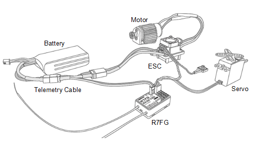 Note Battery connected to TELEMETRY port is only for 2S-8S battery voltage telemetry, R7FG should be powered supplied by connecting to the CH2 pins on right.
Gyro Setup
A. Gyro Enabled
Factory setting is gyro function OFF by default.
Short press ID SET three times with interval less than 1 second, the RED indicator flashes three times. Red LED on/off indicates the gyro function is on/off.
B. Gyro Phase
When the gyro forward is enabled, try to turn the model car to check if the gyro is correcting the wheels. Normally, the wheels should turn right to correct when the car is turned left while the wheels should turn left to correct when the car is turned right. If the gyro phase is reversed, short press the binding button (ID SET) twice in 1 second. The Red indicator flashes twice means the gyro phase setting is complete.
Gyro Sensitivity Adjustment
Gyro sensitivity setting is CH3 by default (factory setting) and can be adjusted by the VR rotary switch. Percentage is displayed when sensitivity is adjusted while the bigger percentage means higher sensitivity. If the VR rotary switch/CH3 is set with other function, MODE can be changed to STD in GYRO setting of the menu to adjust gyro sensitivity with buttons Dec(-) and Inc(-).
Working Mode
R7FG has four working modes:
Mode 1: PWM+PPM output (factory setting by default, NO gyro)
When the Green indicator is on, Channel 1 to Channel 6 output standard PWM whileChannel 7 outputs PPM. Short press ID SET once to change Mode 1 to Mode 2 and three times within 1 second to Mode 4.
Mode 2: PWM+SBUS output(NO gyro)
When theBlue indicator is on,Channel 1 to Channel 6 output standard PWM while Channel 7 outputs SBUS. Short press ID SET once to change Mode 2 to Mode 1 and three times within 1 second to Mode 3.
Mode 3: PWM+SBUS output+ Gyro
When both theRed and the Blue indicators are on (Purple), Channel 1 to Channel 6 output standard PWM while Channel 7 outputs SBUS. Meanwhile, the Gyro function is also on, stabilizing the direction, keeping car from slipping and ensuring safer turning to preventing drifting from fast speed. Short press ID SET once to change Mode 3 to Mode 4 and three times within 1 second to Mode 2.
Mode 4: PWM+PPM output+Gyro
When both the Red and the Green indicators are on (Orange), Channel 1 to Channel 6output standard PWM whileChannel 7 outputs PPM. Meanwhile, gyro function is also on, stabilizing the direction, keeping car from slipping and ensuring safer turning to preventing drifting from fast speed. Short press ID SET once to change Mode 4 to Mode 3 and three times within 1 second to Mode 1.
ALARM (Safety alarm for low voltage and Signal strength)
When the voltage of the transmitter, receiver, vehicle battery, and RSSI signal strength are lower than the set value, there will be a text displayed on the transmitter screen and a "DDD" sound dual alarm prompt to remind you.
You can set the value in the "ALARM" menu: Press “Exit” and “Enter” button at the same time to enter menu, select the "19. ALARM" option, press “Enter” button to access the “ALARM” function interface. The transmitter default alarm voltage It is 5.0V, the receiver default alarm voltage is 4.0V, and the vehicle battery default alarm voltage is 11.1V.The default alarm voltage of single-chip battery is 3.7V. For example, if you use a 3S lithium battery for your model, then the low voltage alarm value should be set to 11.1V (3.7V×3S). The setting method of transmitter and receiver is the same.The default alarm voltage of single-chip battery is 3.7V. For example, if you use a 3S lithium battery for your model, then the low voltage alarm value should be set to 11.1V (3.7V×3S). The setting method of transmitter and receiver is the same.
The RSSI alarm value is turned off by default. Users can set it as the RSSI value corresponding to the farthest safe distance of the actual control. For example, the farthest remote-control distance is 400m, the corresponding RSSI value is -85dBm, then you can set the RSSI alarm value as -85dBm. When the vehicle is running, if the transmitter battery or vehicle battery is exhausted, or the RSSI signal is week, the vehicle will lose control. Therefore, when the alarm sounds, please stop driving immediately and take the vehicle back, check the cause of the alarm, and deal with it properly.
RC6GS V2 Mix Control Setup
RC6GS V2 can be used to control dual-engine models liketracked vehicle has two motors and each track is driven by each motor.
Before setting the mix controls, check if the phases working correctly by pulling trigger and turning the wheel to test throttle and rudder.
Throttle Reverse:NOR/REV
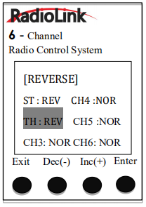 Normally, pull the throttle, the right track should be moving forward whilepush the throttle and the right track should be backward.
If pulling the throttle and the left track moves backward; Or pushing
thethrottle and the left track move forward, meaning the initial
throttle isreversed and needs to be set. Enter REVERSE in the
menu to modify.
Steering Reverse:NOR/REV
Normally, if turn the steering wheel right/clockwise, the left track should be moving forward while turn the wheel left/anticlockwise and the lefttrack should be backward.
If turning the steering wheel right and the right track moves backward;
Or turning the wheel left and the right track moves forward, meaning the
initial steering is reversed and needs to be set. Enter REVERSE in the menu
to modify.
After setting the throttle/ steering reverse, then mix control can be set.
Throttle mix steering:tracked vehicles moving forward/backward
As tracked vehicles moving forward/backward is controlled by throttle, throttle leads steering in the mix control. That is, Master-Throttle, Slave-Steering. Enter PMIX01 in the menu to modify.
* Percentage value varies the speed;
”+”means Master and Slave move to same direction at the same time
Steering mix Throttle:tracked vehicles turning left/right
As tracked vehicles turning left/right is controlled by steering, steering leads throttle in the mix control. That is, Master-Steering, Slave-Throttle. Enter PMIX02 in the menu to modify.
* Percentage value varies the turning angle;
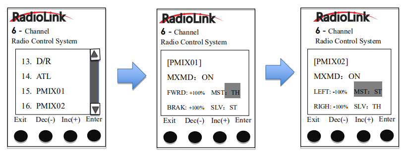 ”-” means Master and Slave move to different directions at the same time
* For more detailed information on function setting please refer to the product user manual on .
For more after-sales service:
Please start from to download the electronic detailed manual.
Or send mail to:
Thank you again for choosing our product.