SAFETY PRECAUTIONS
Never operate your model during adverse weather conditions. Poor visibility can cause disorientation and loss of control of your model.
Never use this product in a crowd and illegal area.
Always ensure the trim levers at 0 and battery properly charged before connecting the receiver.
Always check all servos and their connections prior to each run.
Always be sure about turning off the receiver before the transmitter.
WARNING
This product is not a toy and is NOT suitable for children under the age of 14. Adults should keep the product out of the reach of children and exercise caution when operating this product in the presence of children.
Water or moisture may enter the transmitter inside through gaps in the antenna or joystick and cause model instability, even out of control. If running in the wet weather(such as game) is inevitable, always use plastic bags or waterproof cloth to cover the transmitter.
FCC Statement
This equipment has been tested and found to comply with the limits for a Class B digital device, pursuant to Part 15 of the FCC Rules. These limits are designed to provide reasonable protection against harmful interference in a residential installation. This equipment generates uses and can radiate radio frequency energy and, if not installed and used in accordance with the instructions, may cause harmful interference to radio communications. However, there is no guarantee that interference will not occur in a particular installation. If this equipment does cause harmful interference to radio or television reception, which can be determined by turning the equipment off and on, the user is encouraged to try to correct the interference by one or more of the following measures:
-- Reorient or relocate the receiving antenna.
-- Increase the separation between the equipment and receiver.
-- Connect the equipment into an outlet on a circuit different from that to which the receiver is connected.
-- Consult the dealer or an experienced radio/TV technician for help.
This device complies with part 15 of the FCC Rules. Operation is subject to the following two conditions:
(1) This device may not cause harmful interference, and this device must accept any interference received, including interference that may cause undesired operation.
(2) Changes or modifications not expressly approved by the party responsible for compliance could void the user's authority to operate the equipment.
Packing list (Please refer to the sales interface for the actual packing list)
No. | Items | Quantity |
1 | RC4GS V3 Transmitter | 1 |
2 | R6FG Receiver | 1 |
3 | Lanyard | 1 |
4 | Instruction Manual | 1 |
5 | Packing Box | 1 |
RC4GS V3 Remote Control System
Transmitter RC4GS V3
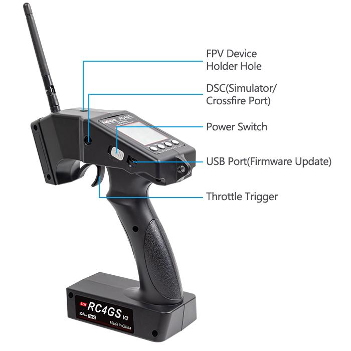
1.1.1 Transmitter Overview
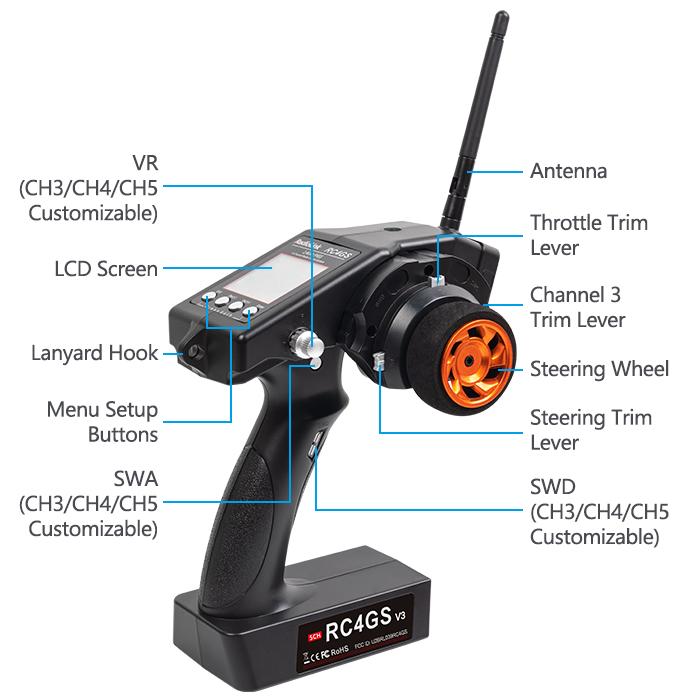
1.1.2 Switch/Button Introduction
Switch/Button | Introduction | Function |
ST | Steering wheel | Default control channel 1 steering. Customizable to control other channels |
TH | Throttle trigger | Default control channel 2 throttle. Customizable to control other channels |
VR | Knob switch | Default control channel 3. Customizable to control channel 3/4/5 |
SwA | Momentary switch | Default control channel 4. Customizable to control channel 3/4/5 |
SwD | Momentary switch | Default control channel 5. Customizable to control channel 3/4/5 |
LK-A | Two-way switch | Lock mode of SwA. Customizable to control channel 3/4/5 |
LK-D | Two-way switch | Lock mode of SwD. Customizable to control channel 3/4/5 |
Two-way switch: The servo value will reach the maximum (or the minimum) when pressing the button once, and back to the original value when pressing the button again. | ||
1.1.3 Specifications
Size: 174.8*116.4*224.2mm(6.88*4.58*8.83") Weight: 319g(11.28oz)
Channel: 5 channels Model Memory: 30
ID seed: 10Antenna Length: 106mm(4.17")
Control Range: 400 metersSpread Spectrum: FHSS
Modulation Mode: GFSK RF Power: <20dbm
LCD Screen: 128*64 Resolution, LCD Backlight Frequency: 2.4Ghz ISM Band(2400MHz--2483.5MHz)
Battery Tray Dimension: 89*59*25mm (3.5*2.32*0.98")Channel resolution: 4096 with regular jitter of 0.5us
Low Voltage Alarm: SupportOperating Current: 80-120mA
Operating Voltage: 4.8-16.8V, (6pcs of AA batteries or a 2S-4S LiPo battery)
Adaptable Models: Car (Incl. Crawlers/Tanks/Caterpillars etc.)/Boat/Robot
Compatible Receiver: R6FG(Standard)/R8FG/R8EF/R8F/R7FG/R6F/R4FGM/R4F
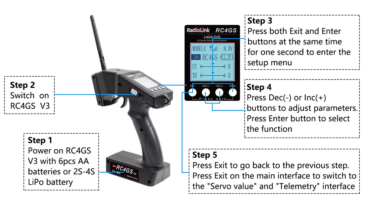
1.1.4 Basic Operations
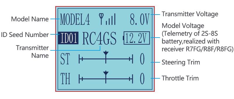
Display on LCD Screen
1.2 Receiver R6FG(Standard Pack)
1.2.1 R6FG Overview
Receiver packed with RC4GS V3 is R6FG, 2.4GHz 6 channels, gyro integrated and high voltage servo supported.
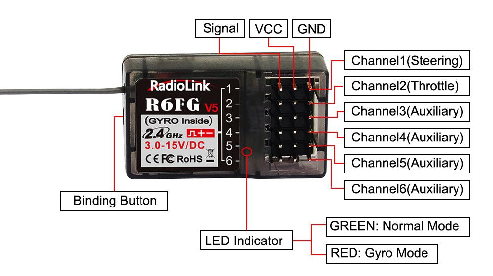
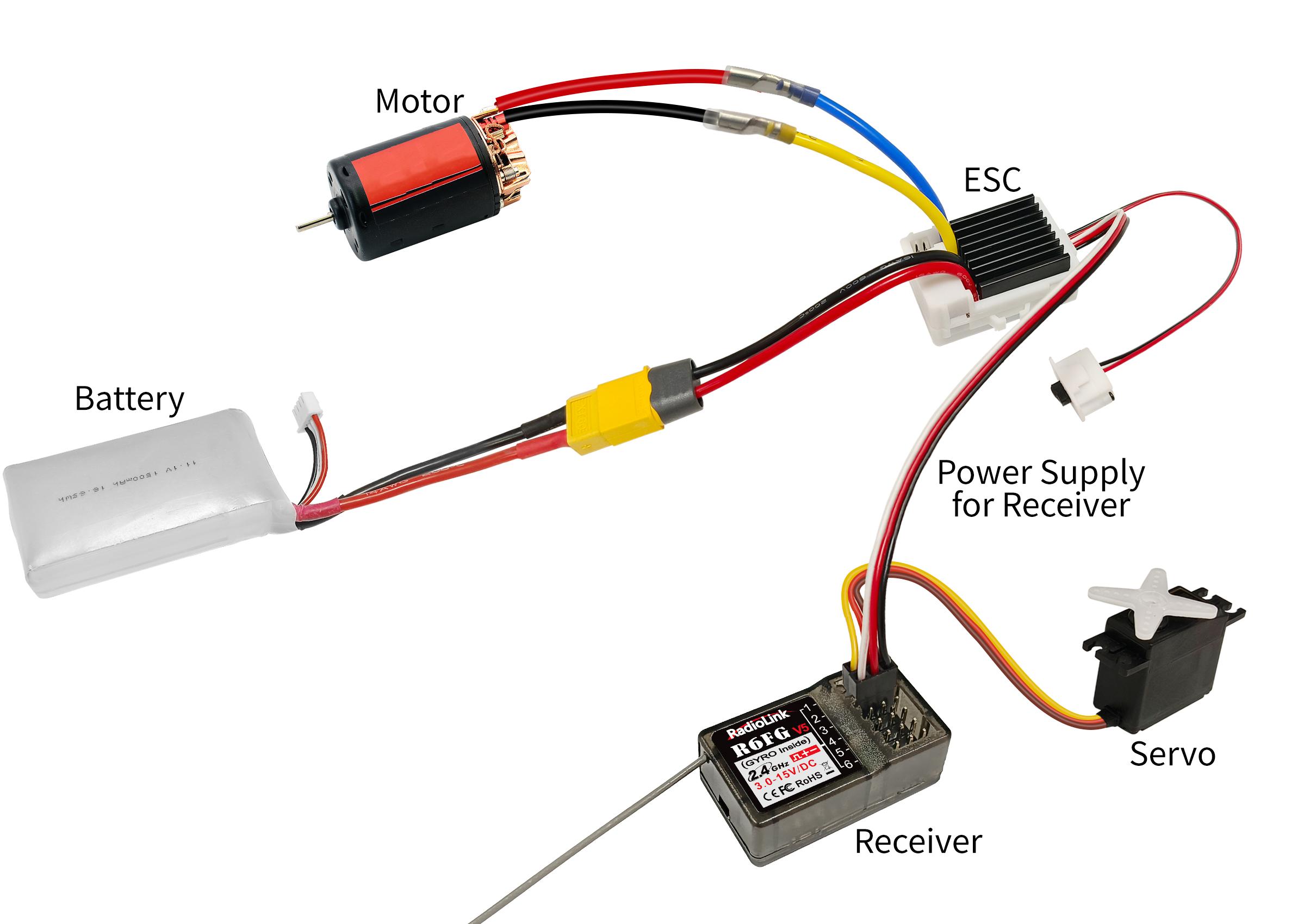
R6FG Connection
1.2.2 Specifications
Size: 35*20*13mm (1.38*0.79*0.51") Weight: 6g (0.21 oz)
Channel: 6 channels Antenna Length: 205mm(8.07")
Operating Current: 30mAOperating Voltage: 3-15V
Control Distance: 400 metersSignal: PWM
Gyro: With gyro-integrated, customizable gyro sensitivity
Applicable Model Types: Car (Including Crawlers/Tanks/Caterpillars)/Boat/Robot
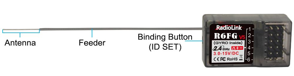
1.2.3 Binding
RC4GS V3 and R6FG have already finished binding by default. Turn on the RC4GS V3 and the R6FG, the signal tower will be displayed on the top of the screen as in the picture right, which means the transmitter and receiver have finished binding.
If you purchase a new R6FG receiver separately, you need to bind the receiver to the transmitter. Each receiver has an individual ID code. When the binding is done, the ID code will be stored in the transmitter and there's no need to rebind.
Binding Steps:
1.Put the transmitter and the receiver close to each other (about 50 centimeters) and power both on.
2.Switch on the transmitter and the LED on R6FG will start flashing slowly.
3. There is a black binding button(ID SET) on the side of receiver. Press the button for more than 1 second and release, the LED will flash quickly, meaning binding process is ongoing.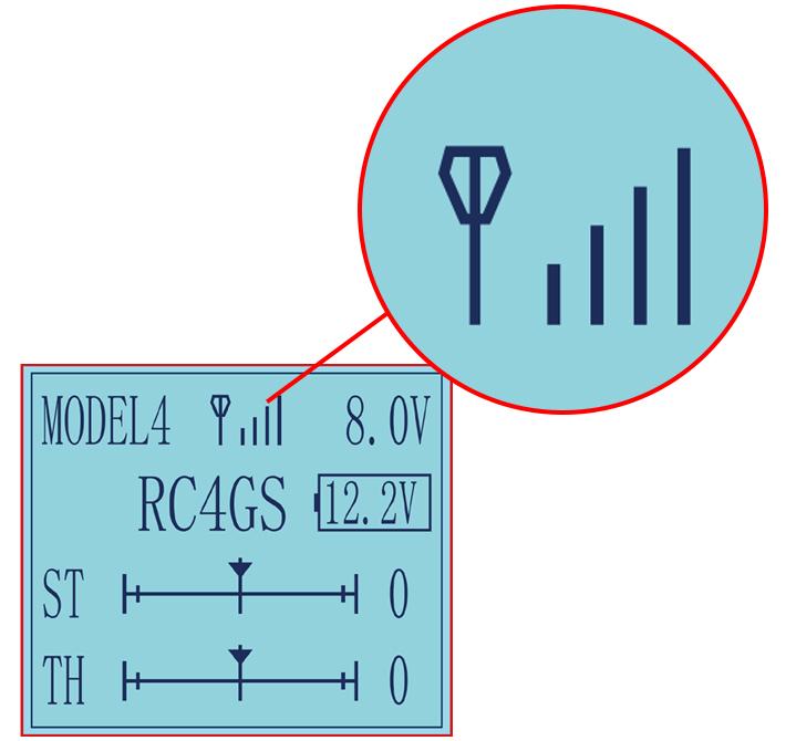
4. When the LED stops flashing and is always on, binding is complete and there will be a signal tower shown on top of the LCD screen of the transmitter. If not succeed, the LED will keep flashing slowly to notify, repeat the above steps.
Note
When binding is done, there’s signal tower on top middle of the screen. As there’s no amplifier module added on R6FG, the signal telemetry from receiver is about 80m(262.5ft). If the distance is longer than 80m, the signal tower may disappear but the control range of RC4GS V3 is as long as 400m(1312ft).
1.2.4 Precautions for Receiver Usage
- Please test RSSI(Received Signal Strength Indicator) before operating models. For methods on how to test it, please refer to Chapter 1.2.8.
- If the antenna of the receiver is damaged, replace it with a new antenna or receiver in time.
- Keep antennas as straight as possible, or the effective control range will reduce.
- Big models may contain metal parts that influence signal emission. In this case, antennas should be positioned at both sides of the model to ensure the best signal status in all circumstances.
- Antennas should be kept away from metal conductor and carbon fiber at least half inch away and no over bending.
- Keep antennas away from motor, ESC or other possible interference sources.
- Sponge or foam material is advised to use to prevent vibration when installing receiver.
- Receiver contains some electronic components of high-precision. Be careful to avoid strong vibration and high temperature.
- Special vibration-proof material for R/C like foam or rubber cloth is used to pack to protect receiver. Keeping the receiver in a well sealed plastic bag can avoid humidity and dust, which would possibly make the receiver out of control.
1.2.5 Working Modes
R6FG has two working modes:normal working mode and gyro working mode. Short press the binding button (ID SET) three times with interval less than 1 second to switch the working modes.
(1) Normal Working Mode
Green LED, gyro will NOT be working.
(2) Gyro Function Working Mode
Both GREEN and RED LED on.
1.2.6 Gyro Setup
The gyro function of receiver R6FG for professional car can be enabled and disabled. When it’s enabled, the turning stability can be maximized during competition. When there is false position, gyro function keeps the car straight forward and turn precisely.
A. Gyro Enabled
Factory setting is gyro function OFF by default. Short press the binding button (ID SET) three times with interval less than 1 second, the RED indicator flashes three times. Red LED on/off indicates the gyro function is on/off.
Attention:
- It's normal that the servo keeps shaking when connected to the receiver. Because the gyro is helping to correct the steering gear angle of the servo automatically if the gyro function has turned on, you can turn off the gyro function if you do not need this function.
- The servo shakes strongly means the gyro is too much sensitive. Please turn DL1 switch to reduce the gyro sensitivity.
- If the receiver has been switched to the gyro mode (with LED indicator ON), but the gyro does not work when turning the car, please enter the menu 20. GYRO to check if the RATE is close to 0%, and increase the RATE.
B. Gyro Phase
When the gyro forward is enabled, try to turn the model car to check if the gyro is correcting the wheels. Normally, the wheels should turn right to correct when the car is turned left while the wheels should turn left to correct when the car is turned right. If the gyro phase is reversed, short press the binding button (ID SET) twice with interval less than 1 second. The RED indicator flashes twice means the gyro phase is switched.
C.Gyro Sensitivity Adjustment
The gyro sensitivity can be adjusted in the BASIC MENU-- GYRO in the transmitter. VR and STD modes are optional. Gyro sensitivity setting is CH3 by default (factory setting) and can be adjusted by VR knob. If VR knob or channel 3 is used for other functions, select STD mode and adjust the gyro sensitivity by buttons Dec(-) or Inc(+) . Percentage is displayed when sensitivity is adjusted while the bigger percentage means higher sensitivity.
1.2.7 Telemetry of Model Battery Voltage
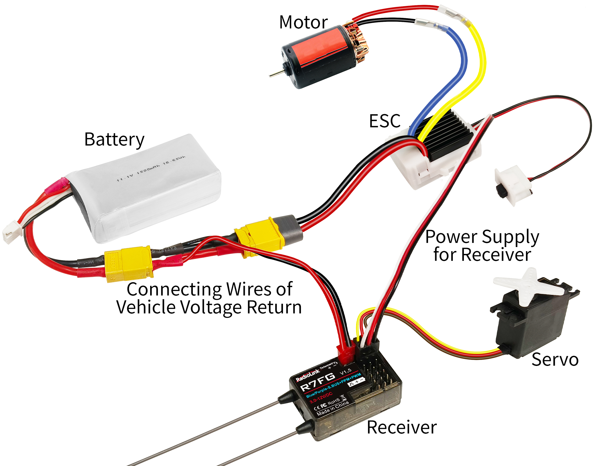
Model battery voltage can be returned in real time when R8FG, R7FG or R8F receiver is used with RC4GS V3 (Note: The standard R6FG receiver does not support the telemetry of model battery voltage.). It can be set in the menu “19. ALARM”. For example, if it is 3S lithium battery used in the model car, the warning value should be set as 11.1V (3.7V*3). The connection is as follows(R7FG is taken as an example):
Note
- Battery connected to TELEMETRY port is only for 2S-8S (7.4V-33.6V) battery voltage telemetry. The TELEMETRY port cannot be used to power the receiver.
- Make sure the polarity of the battery is not reversed. Otherwise reverse insertion will cause abnormal voltage display of telemetry.
1.2.8 RSSI Testing
RSSI stands for Received Signal Strength Indicator.
RSSI test method:
1. After successful binding between the receiver and the transmitter, the signal tower in Picture 1 appears on the screen.
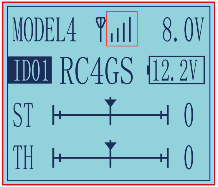
Picture 1
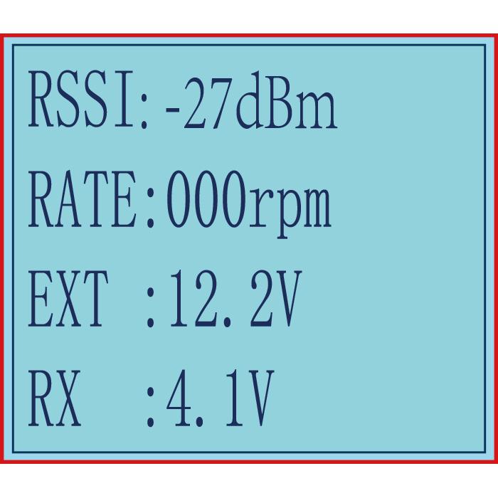
Picture 2
2. Short press the Exit button twice in the home page to enter the return information interface. RSSI is at the top of the interface in Picture 2.
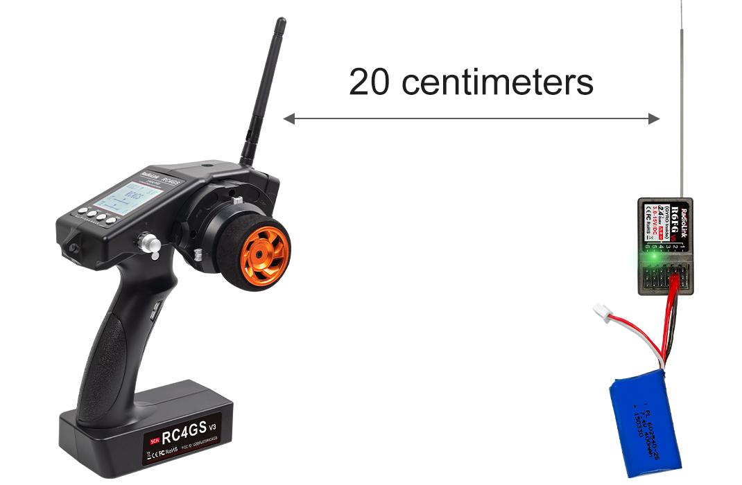
3. Make the receiver antenna and transmitter antenna parallel, and keep a distance of about 20 centimeters from the transmitter(as shown below) to observe the RSSI value. It is normal that RSSI value is within the range of 0 to -30dBm. The closer the value is to 0, the stronger the signal is. If RSSI is not within the range of 0 to -30dBm, the RSSI value is abnormal and there is some problem of signal transmission.
Abnormal Signal Strength Solution:
- Check whether the antenna of the receiver or the transmitter is damaged. If it is damaged, the antenna needs to be replaced.
- If there is no damage of the antenna, you can test the transmitter and receiver for malfunctions by replacing the receiver.
RC4GS V3 Functions
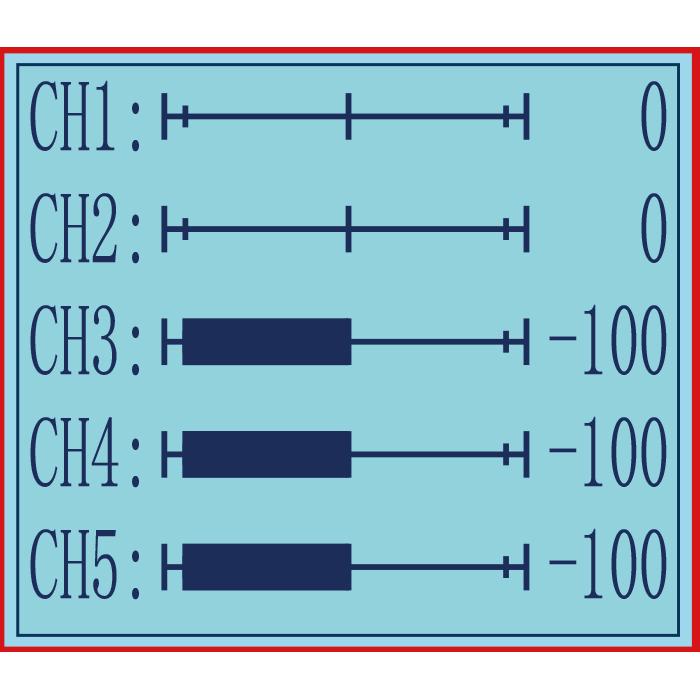
2.1 Servo Value
After powering on RC4GS V3, press the "Exit" button on the main interface to view the servo value (See Picture 1 below).
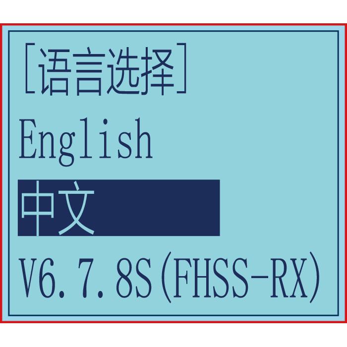
2.2 Language "LANGUAGE"(语言选择)
Both English and Chinese menus are available (See Picture 2 below).
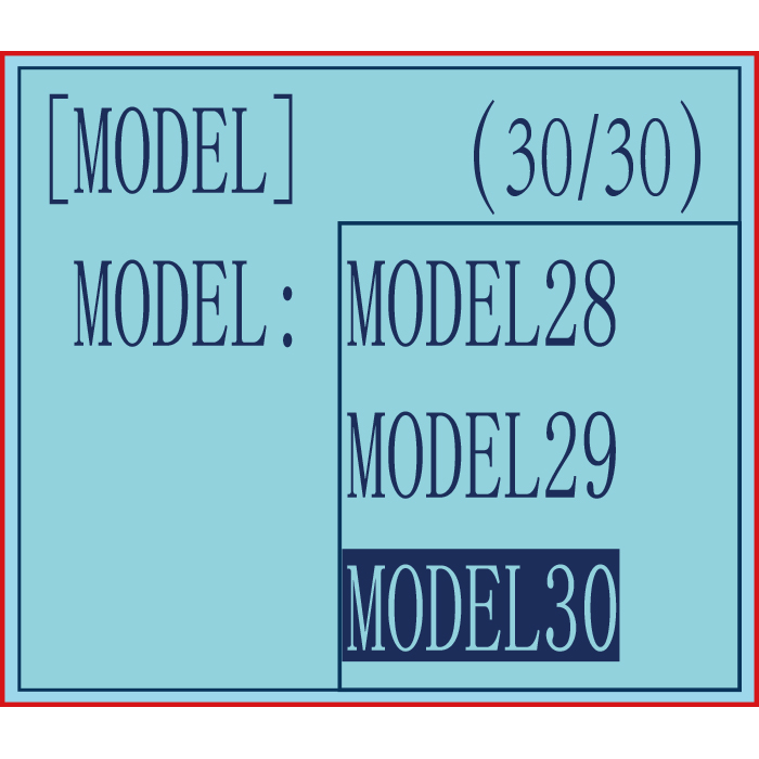
2.3 Model Select "MODEL"
RC4GS V3 can store model memories for 30 models. Use this function to call a new model. Each model can independently set the parameters of each function (See Picture 3 below).
Picture 1 Picture 2 Picture 3
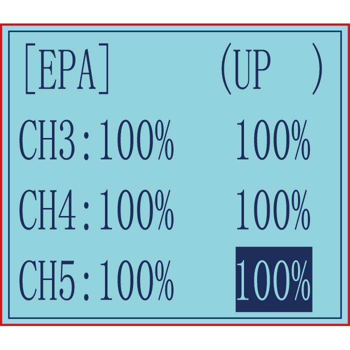
2.4 End Point Adjust "EPA"
Use EPA when performing left and right steering angle adjustments, throttle high side/brake side operation amount adjustment, and channel 3 servo up side/down side operation amount adjustment during linkage.
Correct the maximum steering angle and left and right steering angles when there is a difference in the turning radius due to the characteristics, etc. of the vehicle.
Setting item (channel and value range)
CH1 to CH5: 0%~120%
Initial value:100% 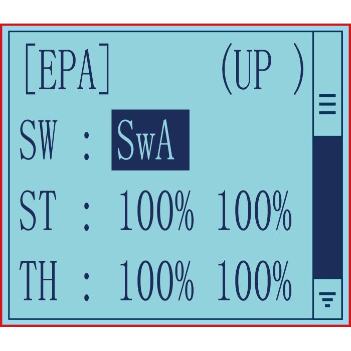
End point adjustment
Switch setting: Set a switch or button to switch in different end points.
A. You can set SWA, SWD, LK-A, LK-D.
B. "NULL" means no switch assigned. After setting the end point parameter of the corresponding channel, the transmitter will always execute the set end point, and it cannot be switched.
C. UP (up)/DOWN (down: It indicates the position of the selected switch. Push/Press the switch to different positions to set different EPA.
2.5 Steering Exponential "STEXP"
This function is used to change the sensitivity of the steering servo around the neutral and both ends position. It has no effect on the maximum servo travel.
RATE: Steering EXP rate
Adjustment range:-100%~0%~+100%
Initial value: 0%
0%~-100%: Sensitivity around neutral position is low, getting higher when approaching ends.
0%: Sensitivity around the neutral and ends position is equal
0%~+100%: Sensitivity around neutral position is high, getting lower when approaching ends
2.6 Steering Servo Speed Delay "STSPD"
Quick steering operation will cause momentary under steering, loss of speed, or spinning. This function is effective in such cases.
Setup item
TURN: turn direction
RETURN: return back to the original direction
Adjustment range
0%~100% (each direction)
At 100%, there is no delay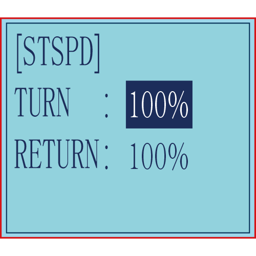
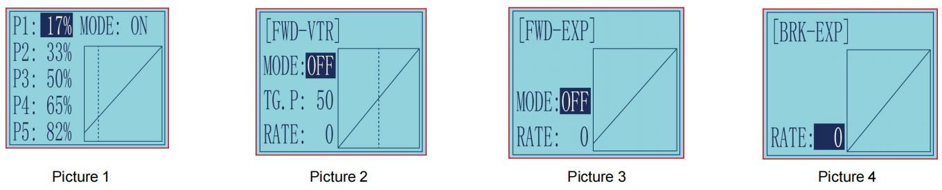
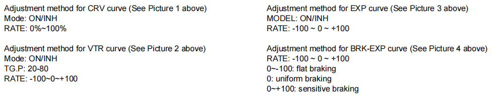
2.7 Throttle Exponential "THEXP"
This function makes the throttle high side and brake side direction servo operation quicker or milder. It has no effect on the servo maximum operation amount. For the high side, selection from among three kinds of curves (CRV/VTR/EXP) is also possible.
The curve can be divided into: Five dots throttle curve adjustment, Single point adjustment, Exponential curve adjustment, Braking index curve adjustment.
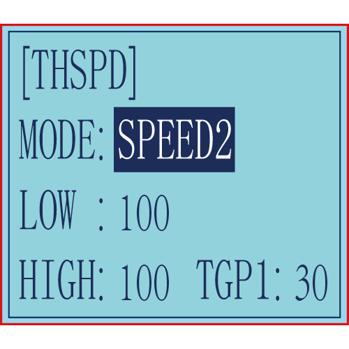
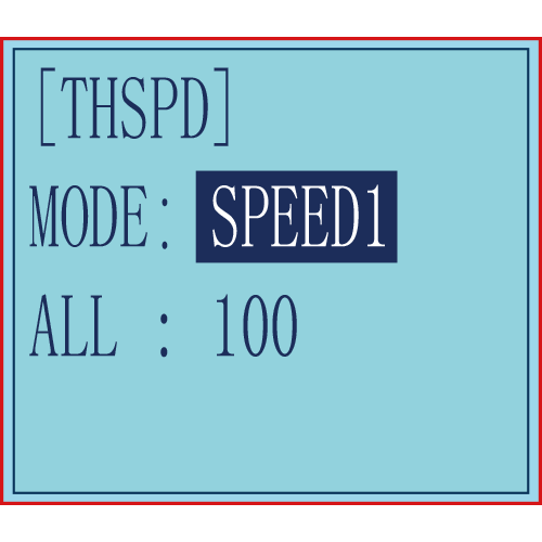
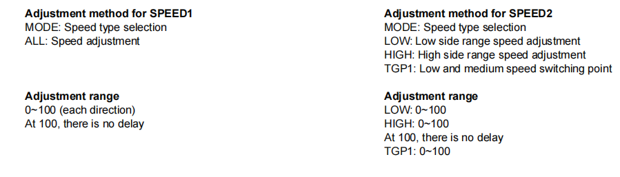
2.8 Throttle Speed Delay "THSPD"
Sudden trigger operation on a slippery road only causes the wheels to spin and the vehicle cannot accelerate smoothly. Setting the throttle speed function reduces wasteful battery consumption while at the same time permitting smooth, enjoyable operation.
Operation
Throttle servo(amp) operation is delayed so that the drive wheels will not spin even if the throttle trigger is operated more than necessary. This delay function is not performed when the throttle trigger is returned and at brake operation.
Speed1 or speed2 can be selected.OFF means shut down the throttle speed function
Picture 1 Picture 2
2.9 A.B.S. Function "A.B.S"
Pulse brake
When the brakes are applied while cornering with a 4 Wheel Drive or other type of vehicle, under-steer may occur. The generation of under-steer can be eliminated and corners can be smoothly cleared by using this function.
Operation
- When the brakes are applied, the throttle servo will pulse intermittently. This will have the same effect as pumping the brakes in a full size car.
- The brake return amount, pulse cycle, and brake duty can be adjusted.
- The region over which the ABS is effective can be set ac-cording to the steering operation. (Mixing function)
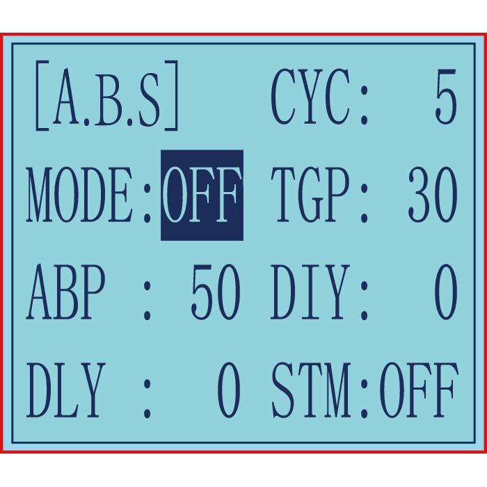
-ABP(Amount of brake return): Sets the rate at which the servo returns versus trigger operation for brake release. When set to 0, the ABS function is not performed. When set to 50, the servo returns 50% (1/2)of the trigger operation amount and when set to 100, the servo returns to the neutral position.
Brake return amount (ABP)
0 ~ 50 ~ 100
Initial value: 50
- Brake return amount (ABP) is influenced by the "EXP" rate on the brake side.
-DLY(Delay): Sets the delay from brake operation to ABS operation.
"0": A.B.S. function performed without any delay
"50": A.B.S function performed after an approximate 0.7 sec delay
"100": A.B.S. function performed after an approximate 1.7 secs delay
Delay amount (DLY): 0 ~ 100
Initial value; 0
-CYC(Cycle): The smaller the set value, the faster the pulse cycle.
Pulse speed adjustment
Cycle speed (CYC): 0 ~ 30
Initial value: 5
- TGP(Trigger point): Sets the trigger point at which the ABS function begins to operate at brake operation. The number is the 100 display with the full brake position made 100%.
Operation point (TGP): 0 ~ 100
Initial value: 30
-DTY(Cycle duty ratio): Sets the proportion of the time the brakes are applied and the time the brakes are released by pulse operation. The ratio can be set to +3 ~ 0~-3 in 7steps.
"-3": Brake application time becomes shortest. (Brakes lock with difficulty)
"+3": Brake application time becomes longest (Brakes lock easily)
(Remark) For low grip set at the - side and for high grip set at the + side.
Duty ratio (DTY): -3 ~ 0 ~ +3
Initial value: 0
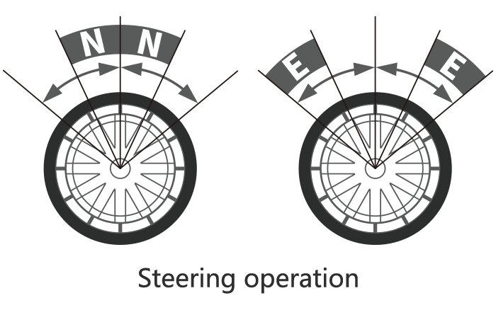
- STM(Steering mixing): Sets the range within which the A.B.S. function is performed relative to steering wheel operation.
Steering mixing (STM)
OFF, N10 ~ N100, E10 ~ E100
Initial value: OFF
When steering mixing is set and steering operation enters the set range, "*" is displayed in front of the number. When mixing is OFF, the A.B.S function can operate over the entire steering range.
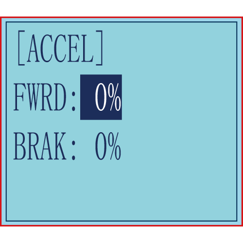
2.10 Throttle Acceleration "ACCEL"
Function which adjusts the movement characteristic from the throttle neutral position.
The servo will jump to the input position at its maximum possible speed. Unlike exponential, which adjusts the whole throttle movement into a curve, throttle acceleration simply "jumps" away from neutral and then leaves the remaining response linear.
FWRD: Forward side acceleration amount
BRAK: Brake side acceleration amount
(1) Forward side acceleration adjustment
"0%": No acceleration
"100%": Maximum acceleration(Approximately1/2of the forward side steering angle)
Forward acceleration amount(FWRD): 0%~100%
Initial value: 0%
(2) Brake side acceleration adjustment
"0%": No acceleration
"100%": Maximum acceleration (Brake side maximum steering angle)
Brake side acceleration amount(BRAK): 0%~100%
Initial value: 0%
2.11 Idle-up "IDLUP"
2.11.1 Idle-up at Engine Start
Use this function to improve the starting characteristics of the engine by raising the idling speed when starting the engine of a gas powered car.
Idle-Up rate (RATE): -50% ~ -1%, 0%, +1% ~ +50%
Initial value: 0%
"-": Brake side
"+": Forward side
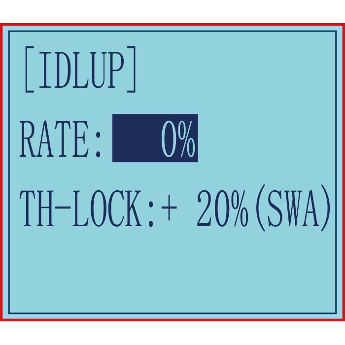
2.11.2 Cruise Control "TH-LOCK"
In addition to adjusting the throttle speed when the throttle trigger is in the neutral position, the Idle up at engine start function can also set the throttle lock, select the throttle value that needs to be locked, and the setting range is -100% to +100%. After the throttle is locked, no matter the current No matter where the throttle trigger is, the throttle output will jump to the set value.
This function is controlled by the trigger of the SWA, two-way switch, press to lock, press again to unlock, the control switch defaults to SWA and cannot be modified.
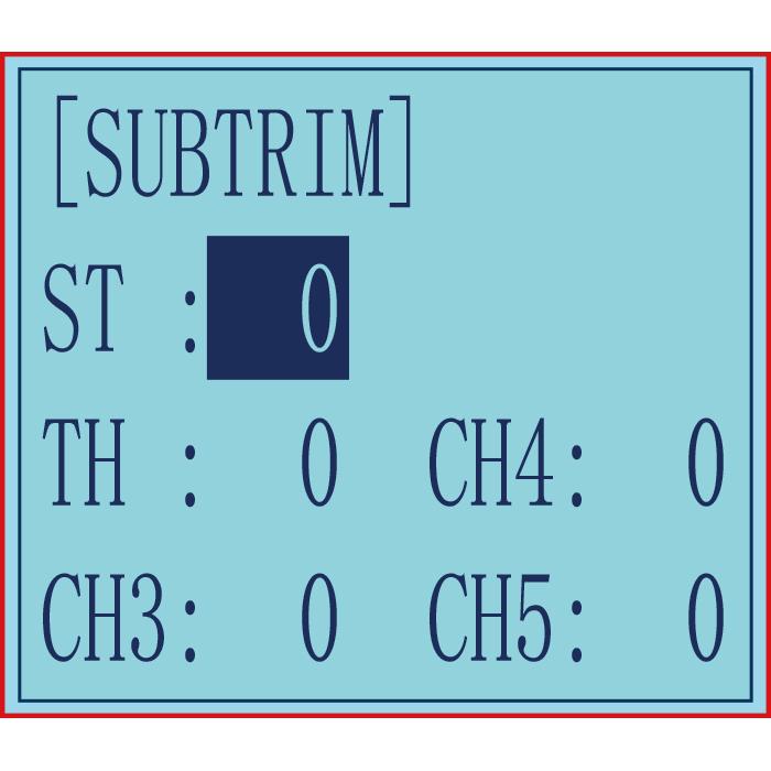
2.12 Sub-trim "SUBTRIM"
Servo center position adjustment
Use this function to adjust the neutral position of the steering, throttle and all other channel.
Sub-trim (channel and value range)
CH1-CH5: -100~0~+100
Initial value : 0
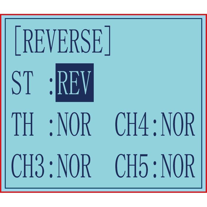
2.13 Channel Reverse "REVERSE"
Servo operation reversing
This function reverses the direction of operation of the servos related to transmitter steering, throttle, channel 3, channel 4, and channel 5 operation.
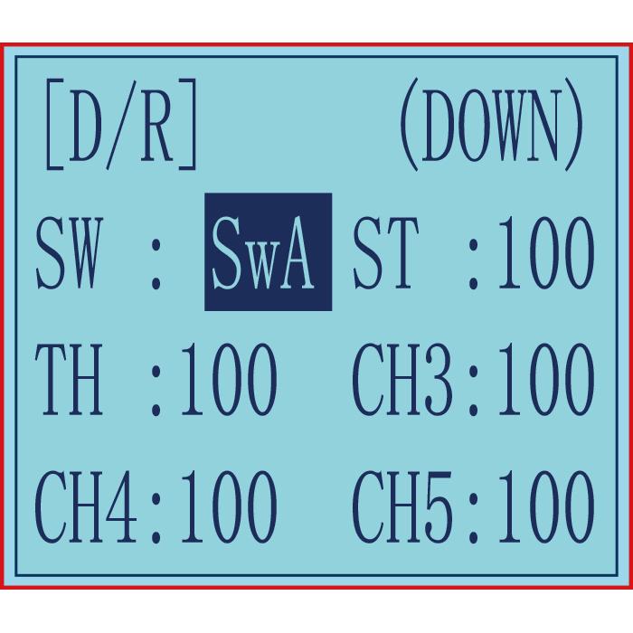
2.14 Steering/Throttle Dual Rate "D/R"
The servo travel amount of all channels can be reduced by Dual Rate setting. Dual rate function is different from EPA, which requires the travel amount on both sides of the channel to be set separately.
Setting the rate of D/R will affect the left and right travel amount at the same time. For example, after setting a smaller throttle value, the travel amount of the model forward and brake will be reduced at the same time, the setting range is 0-100, the default is 100. The steering left and right servo travels are adjusted simultaneously.
Switch setting: Set a switch or button to switch in different travel amount of each channel.
You can set SWA, SWD, or the lock modes of these two switch buttons LK-A, LK-D.
B. "NULL" means no switch assigned. After setting the travel amount of the corresponding channel, the transmitter will always execute the set value by default.
C. UP (up)/DOWN (down): It indicates the position of the selected switch. Push/Press the switch to different positions to set different travel amount.
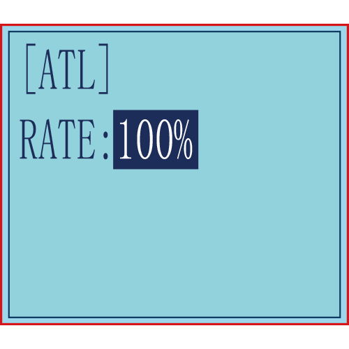
2.15 Brake Side Adjustment "ATL"
This function decreases the set value when the braking effect is strong and increases the set value when the braking effect is weak.
RATE: Brake amount
Brake amount (RATE): 0%~100%
Initial value: 100%
2.16 Programmable Mixes "PMIX01/02"
Programmable mixes between arbitrary channels
These functions allow you to apply mixing between the steering, throttle, CH3, CH4 and CH5. PMIX01 setting is the same with PMIX02.
PMIX:Programmable Mixes
MOD: Mixing mode.
INH: means the mixing function is disabled. Regardless of whether there is a set control switch or value under this function, it is not enabled.
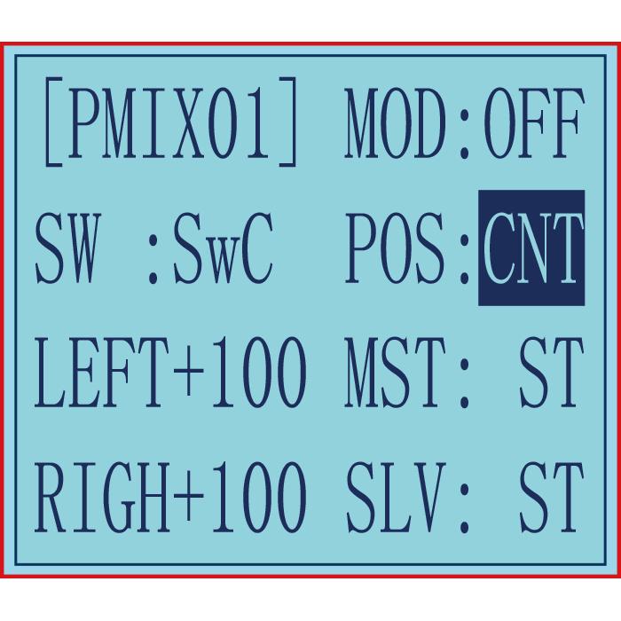
ON/OFF: means turning the function on and off. Set the mode to ON, the current mixing control can take effect.
SW: Switch to control the mix function. You can set SWA, SWD, or the lock modes of these four switch buttons LK-A, LK-D. "NULL" means no switch assigned. After setting the travel amount of the corresponding channel, the transmitter will always execute the set value by default.
POS: means the position of the switch used to control this function. UP (up)/DOWN (down): It indicates the position of the selected switch. Push/Press the switch to different positions to set different travel amount.
LEFT: Mixing rate (Left side)
Mixing amount: -100~0~+100
Select the setting item "LEFT", "FWRD", or "UP"(These setup items are different depend on the master channel. ST: "LEFT"; TH: "FWRD"; CH3:"UP") by pressing “Dec(-)” or “Inc(+)” button.
RIGN: Mixing rate (Right side)
Mixing amount: -100~0~+100
Select the setting item "RGHT", "BRAK", or "DOWN"(These setup items are different depend on the master channel.ST:"RGHT"; TH:"BRAK";CH3:"DOWN") by pressing “Dec(-)” or “Inc(+)” button.
MST: Master channel
Channel selection (MST): ST, TH, CH3, CH4, CH5
Initial value: ST
SLV: Slave channel
Channel selection (SLV): ST, TH, CH3, CH4, CH5
Initial value: ST
2.16.1 Mix Control Setup
The details on how to set the mix control for dual-engine model, please view the link:
https://www.radiolink.com/newsinfo/477940.html
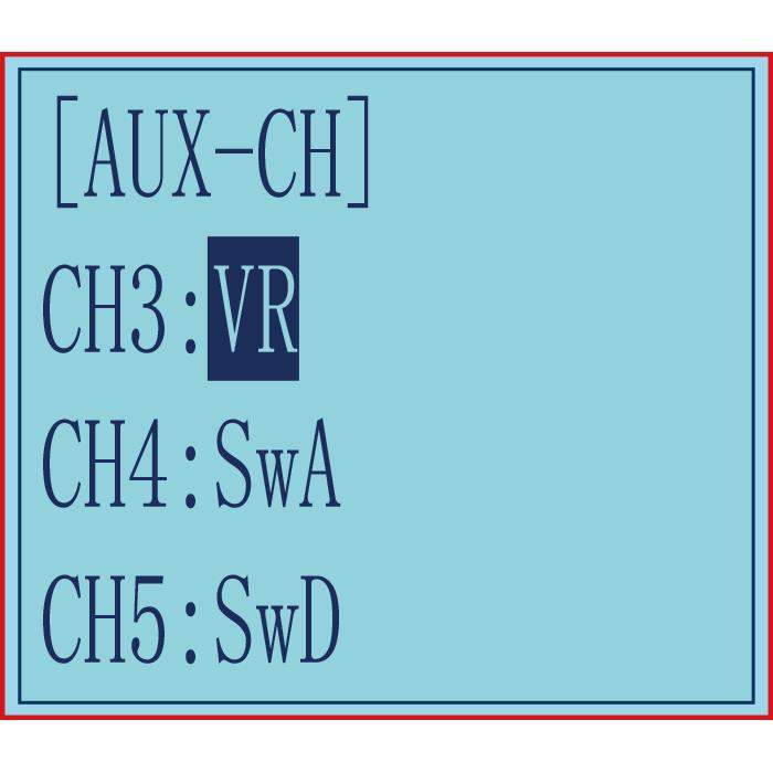
2.17 Auxiliary Channel "AUX-CH"
In addition to the two basic channels of the steering channel (channel 1) and the throttle channel (channel 2), RC4GS V3 also has three auxiliary channels, all of which can be customized to assign control switches.
The control switch of the auxiliary channel can be selected as ST(steering), TH(throttle), VR, SwA, SwD, LK-A, LK-D, NULL.(For more details of all switches, please refer to Chapter 1.1.4 Switch/Button Introduction)
Note: When it is set to NULL, the channel will not be controlled by any switch.
2.18 Model Name "NAME"
RC4GS V3 stores model memories for 30 models. Each model memory can be named separately according to user’s requirement. Factory default name is MODEL1.

2.19 ALARM(Safety Alarm for Low Voltage and Signal Strength)
Each model can independently set low voltage and RSSI value alarms, but the alarm functions of RATE and temperature are not yet available. RPM telemetry functions are still under development. If there are new developments, we will announce them to the RadioLink official website as soon as possible.
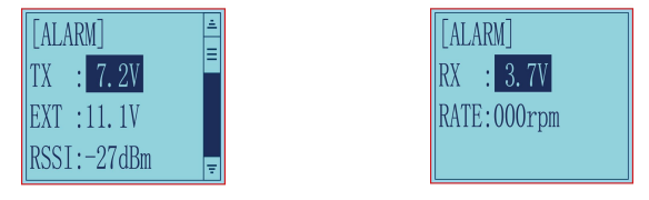
The transmitter default alarm voltage is 7.2V, and it can be customized on 2-4S battery .The receiver default alarm voltage is 4.0V, and the vehicle battery default alarm voltage is 11.1V. The RSSI alarm value is turned off by default. Users can set it as the RSSI value corresponding to the farthest safe distance of the actual control. For example, the farthest remote control distance is 400m, the corresponding RSSI value is -85dBm, then you can set the RSSI alarm value as -85dBm.
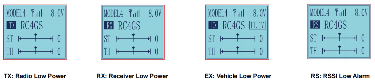
When the voltage of the transmitter, receiver, vehicle battery, and RSSI signal strength are lower than the set value, there will be a text displayed on the transmitter screen(See Pictures below) and a "didi" sound dual alarm prompt to remind you.
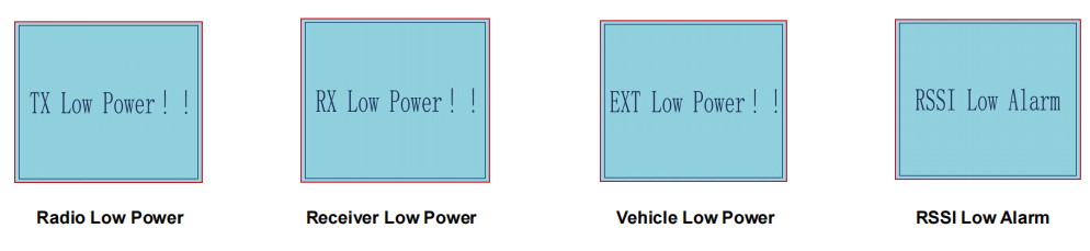
When the above alarm interface appears, press Enter button, the TX, RX, EX, or RS will appears respectively on the home page for reminding the alarm of the transmitter, receiver, vehicle battery, and RSSI (See Pictures below). When the alarm sounds or the warning words of TX, RX, EX, or RSSI appears on the screen, please stop driving immediately and take the vehicle back, check the cause of the alarm, and deal with it properly.
Note:
- RC4GS V3 can set different low voltage alarm values for each model, but the transmitter low voltage alarm is the same for all models.
- Due to the different voltage ranges available for lithium battery, nickel metal hydride and nickel cadmium, please set the corresponding voltage value according to the type of battery you use.
- Model battery voltage telemetry function and model battery low voltage alarm are only valid when using the R8FG/R7FG/R8F receiver.
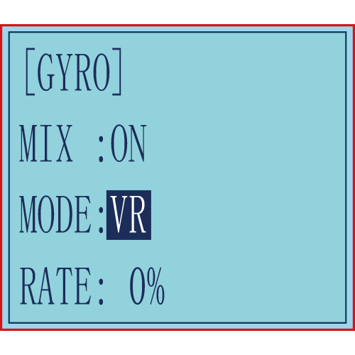
2.20 Gyro Sensitivity “GYRO”
This function is available to set gyro sensitivity and VR mixing ON or OFF.
When MIX set OFF, gyro is disabled while when MIX set ON, you can adjust gyro sensitivity STD or VR. STD is adjusted on screen and VR is default CH3.
In normal mode (STD), range of sensitivity is 0%-100%.
0% means the minimum gyro sensitivity, or even no gyro function; 100% means the maximum sensitivity. If the gyro sensitivity is too high, it may cause the body to vibrate, please adjust the sensitivity according to the vehicle model.
2.21 Fail Safe”F/S”
This function can set the output value of each channel when the receiver loses control. It is set by servo, throttle, CH3, CH4, and CH5.
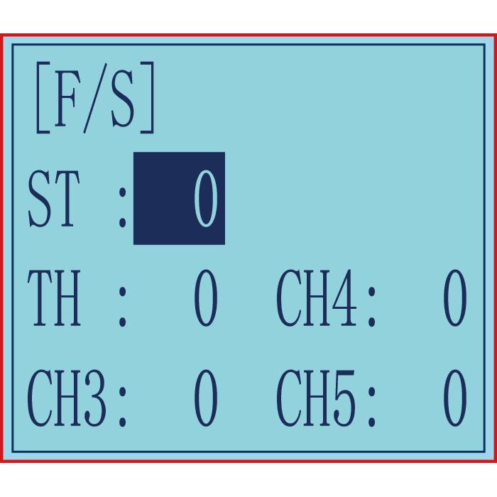
RANGE:
CH1 to CH5: -100~+100
Initial value: 0
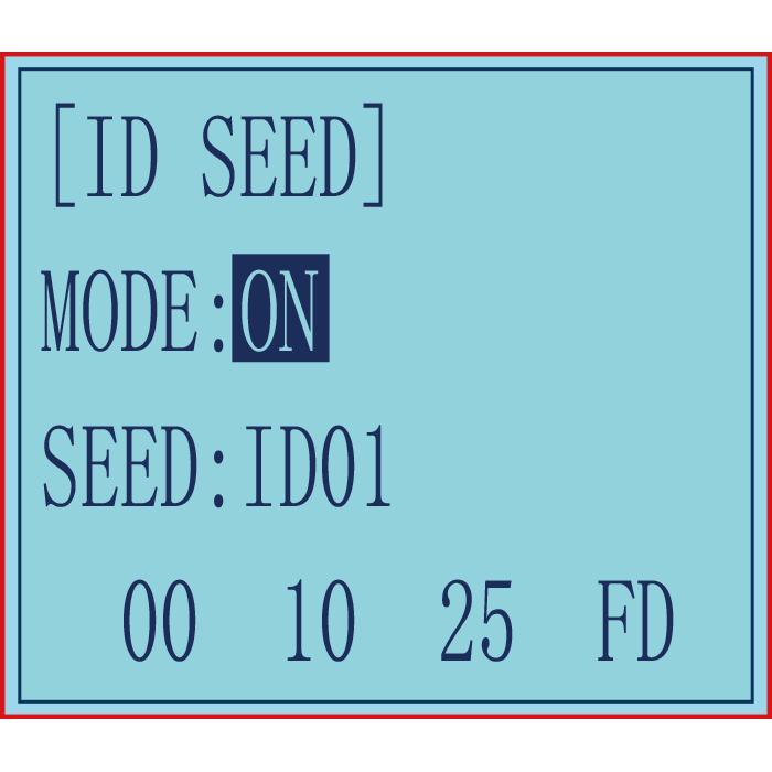
2.22 ID SEED
When the transmitter and multiple receivers that have been successfully paired are powered on at the same time, one of the receivers can be selected to be controlled through the ID SEED function, while the other receivers are in a standby state and cannot be controlled.
The transmitter and receiver have the following two control methods:
1. When ID SEED function is turned off, RC4GS V3 can control multiple devices at the same time.
2. When ID SEED function is turned on, RC4GS V3 can select a receiver from multiple receivers and control this model, while other receivers are on standby.
Setting method:
Turn on the mode, set the corresponding ID SEED number according to the number of your car/boat and complete the binding and other settings. After setting the ID SEED number, the number (such as ID01) will appear on the main interface of the transmitter.
For example: Bind RC4GS V3 with a truck and a car and turn all them on. First, use RC4GS V3 to control the car to run to the bucket of the truck, and then switch the receiver ID on the truck to drag the car back to the destination.
2.23 Timer Setting “TIMER”
TIMER function is mainly used for game timing and daily training.
Mode: Timer mode, you can choose "UP TIMER" or "DOWN TIMER".
UP TIMER: After triggering the timing function, the timing number will count upwards.
DOWN TIMER: After triggering the timing function, the timing numbers will count down.
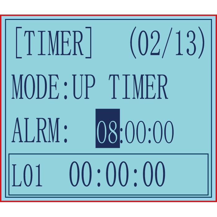
ALRM(Alarm): The timer starts. When it reaches the set time, the transmitter starts to alarm. In the countdown 20S, it starts to alarm every 1S. In the countdown 10S, it starts to alarm twice every 1S. When the alarm time is reached, the transmitter will give a alarm. If the switch is not toggled now, the timing will continue. The default alarm time is 8 minutes. The alarm time can be set according to actual needs
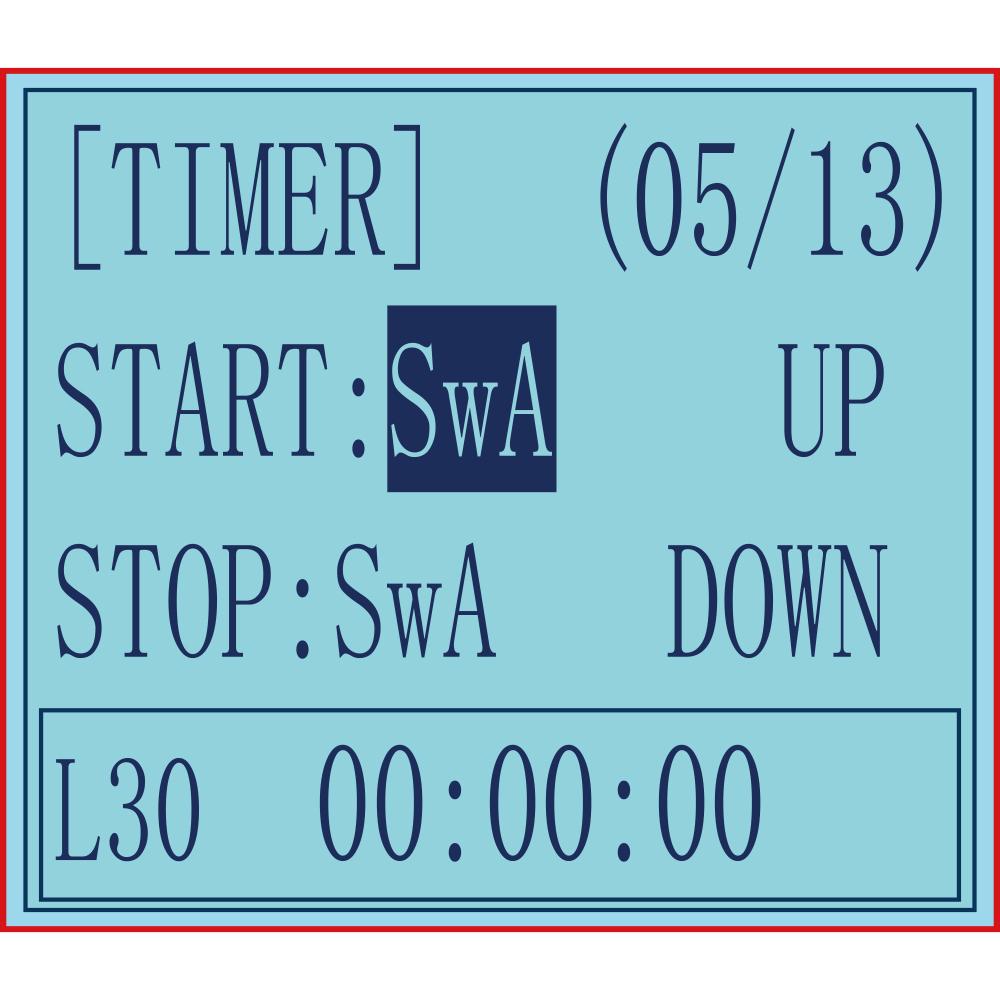
START: Select a switch or button used to trigger the timing function. You can choose SWA, SWD, TH (throttle trigger), and the lock mode of the two switch buttons.
NULL means that the timing function is not enabled. If the switch is set to SWA, SWD or their lock modes, you can select UP (up), or DOWN (down) for the position of the switch to trigger the timing function. If the start switch is TH (throttle trigger), you can set the throttle rate to 0%-100%, and the timing function will be triggered when the throttle trigger is pushed to the set rate.
STOP: It is used to stop the timing function. The setting method is the same as the above "START" setting. When the number of laps set is greater than 1, the number of laps will automatically increase by 1 lap each time it stops.
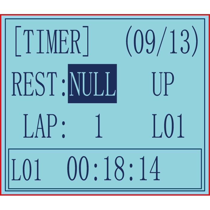
RESET: By toggling the switch set here, all the previously generated timing values will be cleared.Alarm values and laps are retained. The switch setting method is the same as the above "START" setting.
Note:
1. When triggering the timing function, please do not put the switch in the stop or reset position, otherwise the timing function cannot be activated.
2. When the switch is not enough, there are 2 ways to reset all timings: a. By setting the "alarm" value, all timings can be reset. b. All timings can be reset by setting the "mode" value.
LAP: used to set the number of laps required for timing, 1-30 lap numbers can be set;
Display laps: used to display the lap corresponding to the current timing.
L01-L30 can be selected. For example, when it is L02, the timing below correspond to Lap 2. When the number of laps set is greater than 1, the number of laps will automatically increase by 1 lap each time it stops.
Check the timing of each lap: move the cursor to: L01-L30, press the "Enter" button, the cursor starts to blink, and then press the "Dec(-)" or "Inc(+)" buttons at the bottom of the screen to select the laps to check the timing time. The corresponding timing lap and timing will be displayed in the box below.
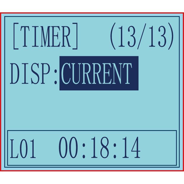
Display: CURRENT, the ON or OFF status of the timing function is only displayed in the function menu of "Timer".
HOME PAGE, the ON or OFF status of the timer function is displayed both in the "Home Page" and "Timer" menu at the same time.
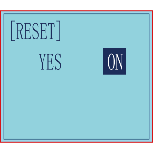
2.24 Factory Reset “RESET”
RESET- Data reset function: All the data for any model memory can be reset to original factory defaults. Often this function is done to get a “fresh start” and clear the memory before inputting new model settings.
Note: Resetting the current model memory will permanently erase ALL programming information for that model. The data cannot be recovered. Do not reset the model unless you are certain you want to clear-out that memory and start from scratch.
III. Tutorials
Please search Radiolink_official on YouTube to access RadioLink official channel and check all the below video tutorials of RC4GS V3. View the playlist of RC4GS V3 or search key words on our channel for the function you want.
3.1 Firmware Update of RC4GS V3
3.2 Throttle and Steering Calibration
3.3 Connect RC4GS V3 to Simulator
3.4 THSPD Throttle Delay Function on RC4GS V3
3.5 TIMER Function on RC4GS V3
3.6 Dual Rate Function on RC4GS V3
3.7 EPA Function on RC4GS V3
3.8 Set Different ALARM for 30 Different Models on RC4GS V3
3.9 ID Seed Function on RC4GS V3
3.10 Cruise Control Function on RC4GS V3
3.11 Connect RC4GS V3 to TBS Crossfire
3.12 LK-A/LK-D Button Setup on RC4GS V3
Technical Support Here