R8F
(FHSS)
INSTRUCTION MANUAL
8-channel receiver
Two-way Transmission Telemetry
PWM&PPM&SBUS Signal Supported
RadioLink Electronic Ltd
Thanks for purchasing RadioLink 8-channel dual antenna receiver R8F.
To fully enjoy the benefits of this product and ensure safety, please read the introduction carefully and set up the device as instructed steps.
If any problems found during the operation process, please kindly refer to the manual first. Then you could contact our distributors to find solution or follow our Facebook homepage to search related key words. Also you can send your questions to or and we will answer your question at the earliest.
Due to unforeseen changes in production procedures, the information contained in this manual is subject to change without notice.
For more information please check our website and follow our Facebook and Youtube homepage.

SAFETY PRECAUTIONS
Never operate your model during adverse weather conditions. Poor visibility can cause disorientation and loss of control of your model.
Never use this product in a crowd and illegal area.
Always ensure the trim levers at 0 and battery properly charged before connecting the receiver.
Always check all servos and their connections prior to each run.
Always be sure about turning off the receiver before the transmitter.
WARNING
This product is not a toy and is NOT suitable for children under the age of 18. Adults should keep the product out of the reach of children and exercise caution when operating this product in the presence of children.
Water or moisture may enter the transmitter inside through gaps in the antenna or joystick and cause model instability, even out of control. If running in the wet weather(such as game) is inevitable, always use plastic bags or waterproof cloth to cover the transmitter.
Content
R8F Introduction
1. R8F Basic Introduction
1.1 Compatible transmitters
RadioLink R8F 2.4G 8-channel receiver can return the real-time informationsuch as RSSI, receiver voltage and model battery voltage and support high voltage, compatible with RadioLink 6CH radio RC6GS, 4CH radio RC4GS, RC3S,RC4G and 8CH radio T8FB and T8S.
Note
To realize the functions of two-way transmission telemetry, the corresponding latest firmware needs to be flashed.
RC6GS - V6.0.0 (Compatible with RC6GS 3-position switch version ONLY)
RC4GS - V6.0.1 (Compatible with RC4GS produced AFTER Jan.1, 2018 ONLY)
The other models RC6GS with 2-position switch, RC4GS produced before 20180101, T8FB, T8S, RC3S and RC4G can bind to R8F though the functions of 2-way transmission can’t be realized.
1.2 Binding
Each receiver has an individual ID code and must bind with transmitter before using. When the binding is done, the ID code will be stored in the transmitter and there’s no need to rebind. Therefore, when a new R8F is purchased, binding needs to be done in order to work with transmitter.
Binding steps:
Put the receiver and the transmitter together within 30-50cm.
Power on the transmitter and R8F will bind to the closest transmitter automatically.
Press the ID SET on the receiver’s side for more than 1s and the LED will flash, meaning the binding process has begun.
When the LED stops flashing, binding is complete.
Test the model servo to make sure it can be operated by the transmitter.
Note:
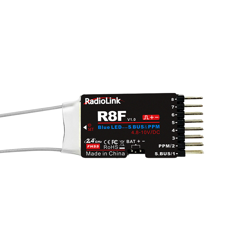
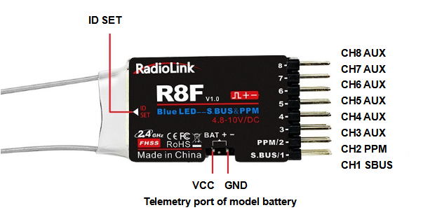
PWM signal output mode by default as factory setting. There are two LED indicators on R8F. RED LED (always on) indicates normal working mode while RED+BLUE LED (always on) indicate SBUS/PPM signal output mode.
When R8F is powered on, the FLASHING RED LED means no signal or binding WITHOUT success. Please bind the receiver to the transmitter.
Telemetry
R8F can return the real-time informationsuch as RSSI, receiver voltage and model battery voltage.
In order to enjoy this function, please upgrade RC6GS(3-position switch version) with the firmware RC6GS_RadioLink_bin_1d15_V_6_0_0 downloaded via
Or upgrade RC4GS(produced after 2018-01-01) with the firmware RC4GS_RX_RadioLink_bin_2f50_V_6_0_1 downloaded via
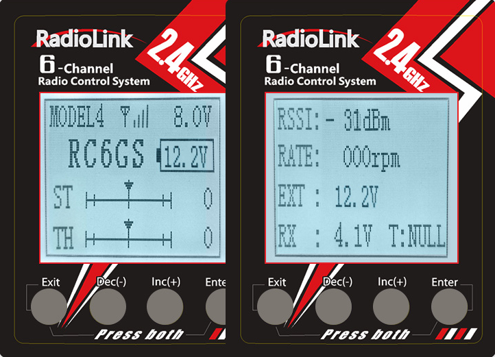
2.1 Telemetry of Signal and RSSI
Power on the transmitter and the receiver and complete the binding, signal will be displayed on the homepage of transmitter. Short press EXIT twice and enter the interface with returned information including RSSI value.
Warning can be set with a certain low RSSI value after testing by changing distance:
Press EXIT and ENTER simultaneously to enter MENU=>press Inc(+) to highlight “19. ALARM =>Press ENTER to (dis)activate the warning and set the RSSI warning value.
2.2 Telemetry of model battery and receiver voltage
Besides the return of receiver voltage, model battery voltage (maximum up to 8S lithium battery) can also be returned in real time. Users can personalize the warning value of low model battery voltage depending on the actual needs.
Press EXIT and ENTER simultaneously to enter MENU=>press Inc(+) to highlight “19. ALARM =>Press ENTER to set the model battery voltage warning value.
Normally we set the warning value with the single cell voltage as 3.7V. For example, if it is 3S lithium battery used in the model car, the warning value should be set as (3.7V*3S=)11.1V.
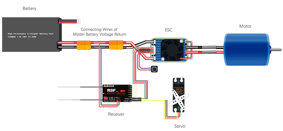
Model battery voltage return can be easily achieved by connecting the male end of the battery wire to ESC while the female end to the battery and the wire with a JST head connects BAT (+-) of R7FG/R8F as below pic shown. No extra module is needed.
3. Working Modes
R8F has two working modes:Standard working mode and S.BUS/PPWM signal output working mode.
3.1 Standard working mode
When the RED indicator is on,CH1 to CH8 with PWM signal output , Besides CH1 for steering and CH2 for throttle , CH3 to CH8 are auxiliary channels to connect extended functions such as light modules and buzzer and so on
Short press ID SET two times with interval less than 1s, the indicator from RED to BLUE ,meaning the working mode from PWM working mode to SBUS/PPM signal output working mode.
3.2 PWM+SBUS/PPM signal output working mode
When the BLUE indicator is on , flight controller can be connected and works with GPS to make true the RTL function of shipping boat or setup of mecanum wheel models
Short press ID SET two times with interval less than 1s, the indicator from BLUE to RED ,meaning the working mode from SBUS/PPM signal output working mode to PWM working mode .
4. R8F Specifications
Frequency:2.4GHz ISM band(2400MHz~2483.5MHz)
Dimension: 34*21*11.5mm
Weight: 6.5g
Channel Qty::8 channels
Signal Output:PWM/PWM&SBUS/PWM&PPM
Model Application: Car/Boat/Fixed Wing/Glider/Multirotor
Encode: FHSS 67-channel pseudo random frequency hopping
Antenna Length:200mm(dual antennas)
Voltage Range:4.6-10V DC
Channel Resolution: 4096
Operating Current: 30mA ( Depending on power supply)
Telemetry: Signal/RSSI/Model Battery Voltage
Control Distance: 1900 meters on the ground
5. Note of Antenna Installation
In order to maximize the signal transmission, it’s greatly advised that
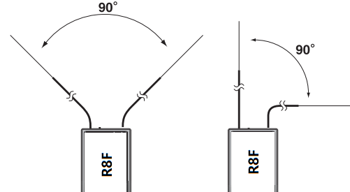
Keep antennas as straight as possible, or the effective control range will reduce.
Keep the two antenna in 90° angle as shown below
Big models may contain metal parts that influence signal emission. In this case. antennas should be positioned at both sides of the model to ensure the best signal status in all circumstances.
Antennas should be kept away from metal conductor and carbon fiber at least half inch away and no over bending.
Keep antennas away from motor, ESC or other possible interference sources.
Sponge or foam material is advised to use to prevent vibration when installing receiver.
Receiver contains some electronic components of high-precision. Be careful to avoid strong vibration and high temperature.
Special vibration-proof material for R/C like foam or rubber cloth is used to pack to protect receiver. Keeping the receiver in a well sealed plastic bag can avoid humidity and dust, which would possibly make the receiver out of control.
When all the above steps are complete, please turn off the transmitter and repower on to test if the receiver is correctly bind with it.