
1 CrossRace Introduction
1.1 Spare Parts
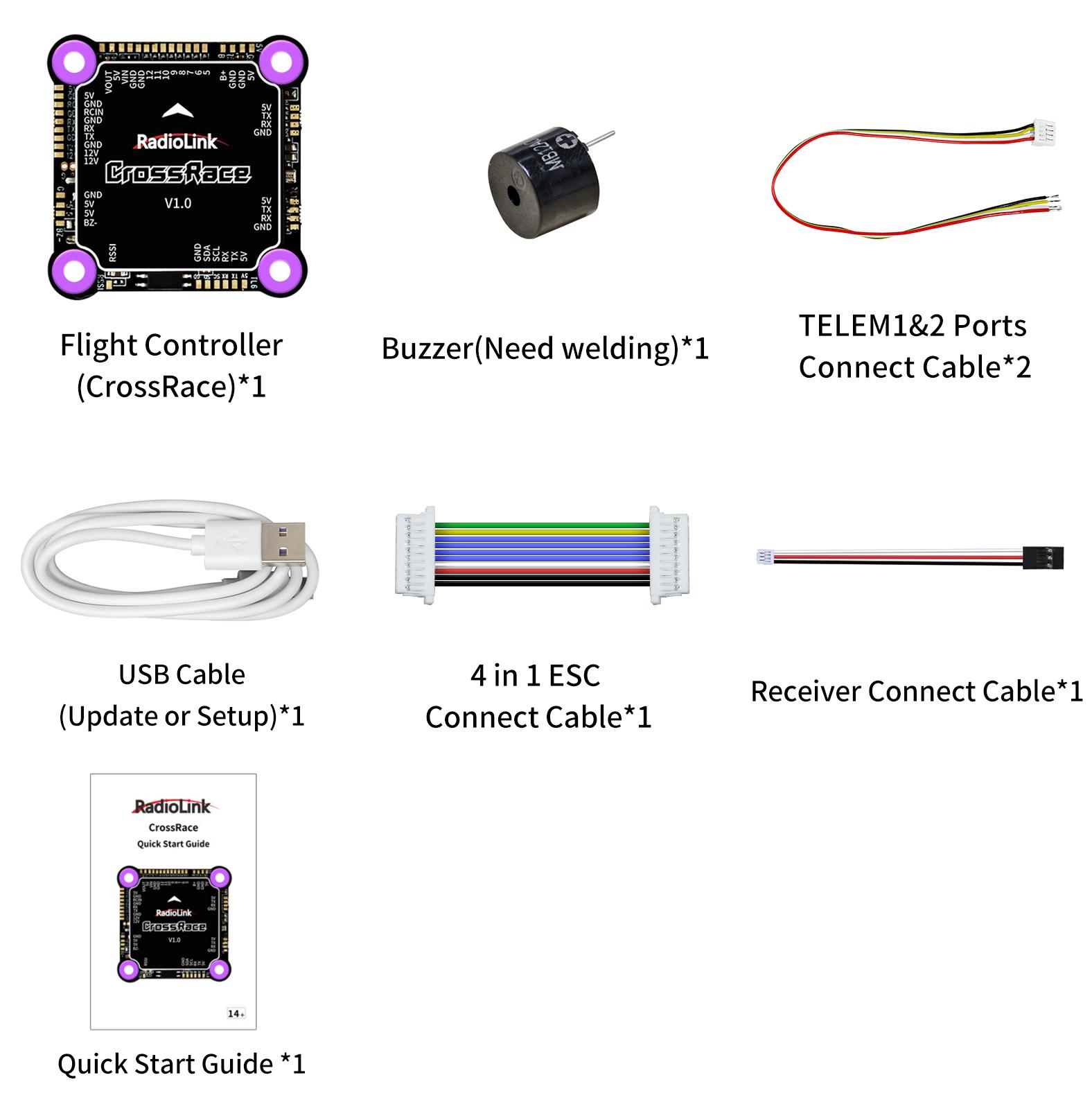
1.2 Connectors
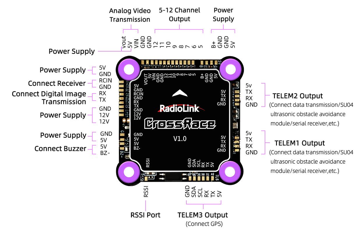
Definition of Each Port of the Soldering Plate
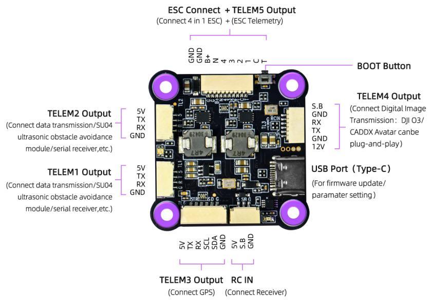
Definition of Each Port of the Socket
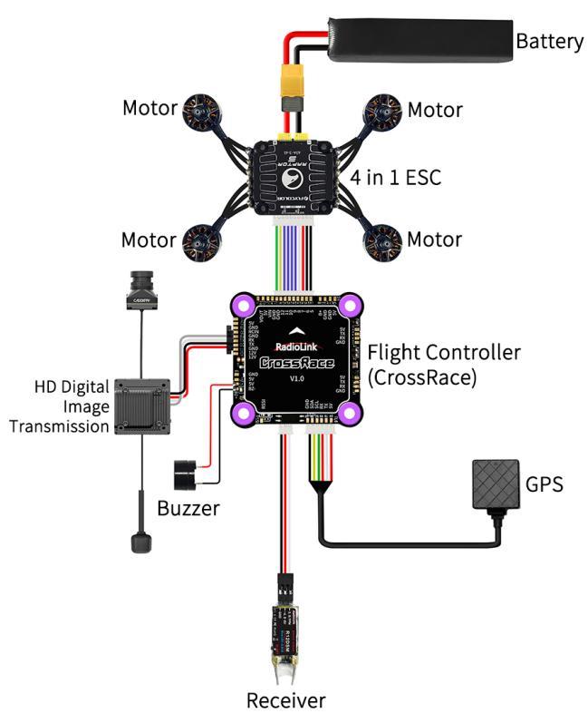
Connection Diagram of CrossRace to Multi-rotor
CrossRace serial ports:
CrossRace has a total of five serial ports: TELEM1, TELEM2, TELEM3, TELEM4, and TELEM5.
Serial Port | Function |
TELEM1 | Custom serial port |
TELEM2 | Custom serial port |
TELEM3 | GPS |
TELEM4 | Digital image transmission |
TELEM5 | ESC telemetry |
Among them, serial ports 1 and 2 are custom serial ports. Serial port 3 defaults to the GPS interface. Serial port 4 defaults to the digital image transmission interface, and serial port 5 defaults to the ESC telemetry interface.
External power supply for CrossRace:
CrossRace supports a total of 3 voltage ranges to power external devices, namely 5V, 12V, and B+.
B+: The battery voltage that powers the ESC and flight controller is the voltage output by the B+ pin of the CrossRace flight controller. Therefore, when an external device needs to be powered through the B+ pin of the CrossRace flight controller, please make sure the battery voltage does not exceed the working voltage range of your external device to avoid damaging the external device due to high-voltage input.
5V: Regardless of the voltage of the battery that powers the ESC and flight controller, the 5V pin on the CrossRace flight controller always outputs 5V voltage to external devices.
12V: If the battery voltage that powers the ESC and flight controller is higher than 12V, the 12V pin on the CrossRace flight controller will only output 12V to external devices. If the battery voltage is lower than 12V, the 12V pin will output the actual battery voltage to the external device.
1.3 Specifications
Weight & Dimension | Mounting Hole Distance | 30.5*30.5mm |
Weight | the connect wires included) | |
Hardware | Processor | HC32F4A0PITB |
Sensor | Gyro | BMI323 |
Compass | None | |
Barometer | SPL06 | |
FRAM | for multi-copters | |
Buzzer | 1 | |
Safety Switch | None | |
Connector | Type | and soldering pads |
ESC Connector | and current monitor and ESC telemetry | |
Channel Output | 12 Channels Output | |
Mavlink UART | 2 (Without CTSRTS) | |
USB Port | 1 (Type-C) | |
GPS UART / I2C Port | 1 | |
RC In Signal Input | PPM/SBUS | |
Transmission Plug-and-play | Video Transmission Plug-and-play | |
RSSI Output | Support | |
OSD Module | Support, OSD Module integrated | |
ESC Protocol | PWM, DShot, and OneShot | |
RTK | Support | |
Redevelopment | Support | |
Input Voltage | 2-6S | |
Input Current | 5A | |
Adaptable Models | 2-8 Copters | |
Operating Parameters | USB Voltage | 5V±0.3V |
Operating Temperature | -30~85° | |
1.4 Advice
For the users who first use CrossRace, we suggest that you use CrossRace following below steps:
1. You have to install the mission planner and driver from here and familiar with the menu. To establish a connection, you must first choose the communication method/channel you want to use, and then set up the physical hardware and Windows device drivers. You can connect the PC and autopilot using USB cables, Telemetry Radios, Bluetooth, IP connections etc.
Download the update firmware by USB cable if you need.
Connect flight controller to Mission Planner, and connect receiver to finish the calibration of transmitter, Accelerometer and compass.
Setup RC transmitter flight mode.
Assemble aircraft and finish the pre-flight checklist.
PID usage.
Advanced configuration.
Note: When the aircraft switches from auto-throttle mode (such as AltHold mode, PosHold mode etc.) to manual mode (ACRO), please check whether the throttle stick is in the lowest position when switching flight modes, If the stick is in the middle position, the aircraft will rush upwards, which may cause dangerous consequences such as loss of control, crash, and casualties.
2 Mission Planner
2.1 Install Mission Planner
Net Framework 4.6.2 needs to be installed first before Mission Planner; you can download Net Framework 4.6.2 here:
After installing Net Framework 4.6.2, you can download the Mission Planner of CrossRace from the link here:
https://www.radiolink.com.cn/crossrace_missionplanner
Open the Microsoft installer file and select Run to run the installation utility.
2.2 Mission Planner Introduction
Once installation is complete, open Mission Planner by clicking on its system icon.
Once the installation of Mission Planner and driver is done, there will several pop-ups when you open the MP at the first time. The first pop-up clicks Yes and the others click NO.
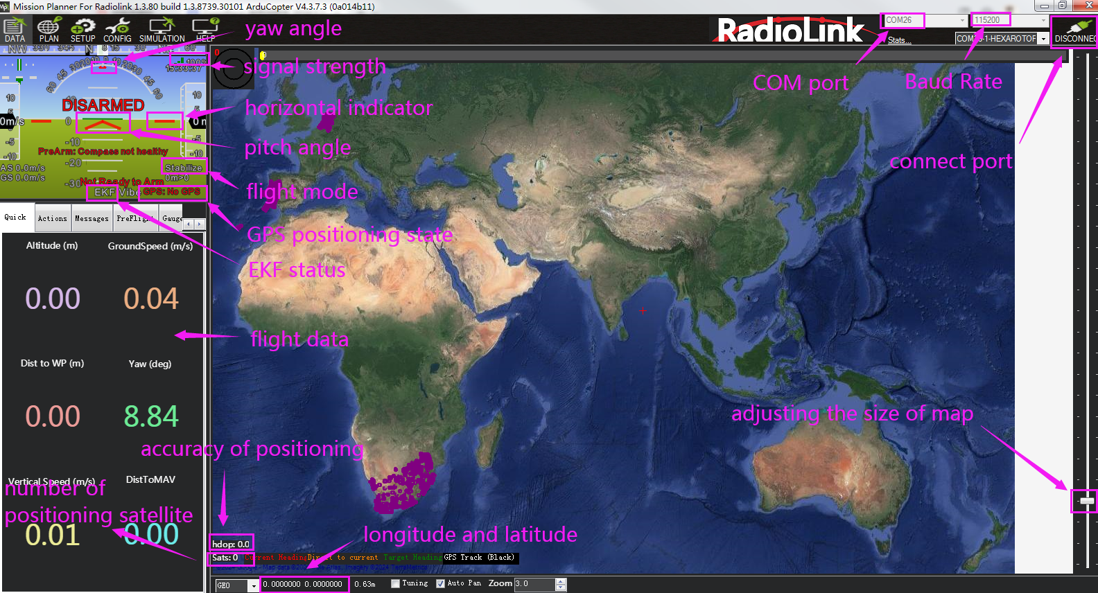
There are six Menu Button in main menu.
FLIGHTDATA: flight attitude and data will show in real time on MP
FLIGHTPLAN: planning the flight mission
INTIAL SETUP: for firmware installation and update, Mandatory Hardware and Optional Hardware setup
CONFIG/TUNING: including detailed PID setup and parameters change
SIMULATION: make CrossRace work as a simulator after upgrade a special simulation firmware
HELP: you can get help when you have questions about MP
3 Initial Setup
* CrossRace can set parameters or update firmware by RadioLink Mission Planner, ArduPilot Mission Planner, and QGC Mission Planner.
* CrossRace can only update firmware from RadioLink, and cannot update the open-source firmware. CrossRace only supports the firmware for multi-rotor, and it has loaded the parameters of the 5-inch drone by default.
CrossRace Firmware download link:
https://www.radiolink.com.cn/crossrace_firmware
3.1 Download and Install Firmware
Please connect your CrossRace and computer via USB cable. Open the Mission Planner to loading the firmware you need to your CrossRace.
Attention:
(1) Do not click CONNECT before you upload the new firmware, please click DISCONNECT if you have connected successful before. Upload new firmware will be not success if you have connected already.
(2) Please do not upload new firmware by wireless data transmission because it has missed the reset signal.
(3) If there’s without firmware version number, it means failed upload new firmware. It may cause of network problem, please re-upgrade firmware until shows the version.
There are two ways to install firmware online.
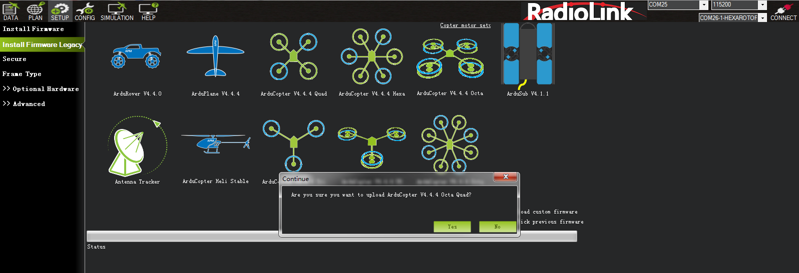
Click Install Firmware”, and connect the flight controller and the computer with a USB cable. When Mission Planner displays the following picture ① (If there is no such prompt, please unplug the USB cable and plug it again until the prompt appears), click the firmware of the model you want, and then click Yes to install the firmware. If the following picture ② appears, select your flight controller, and click Upload Firmware and wait for the firmware to be installed.
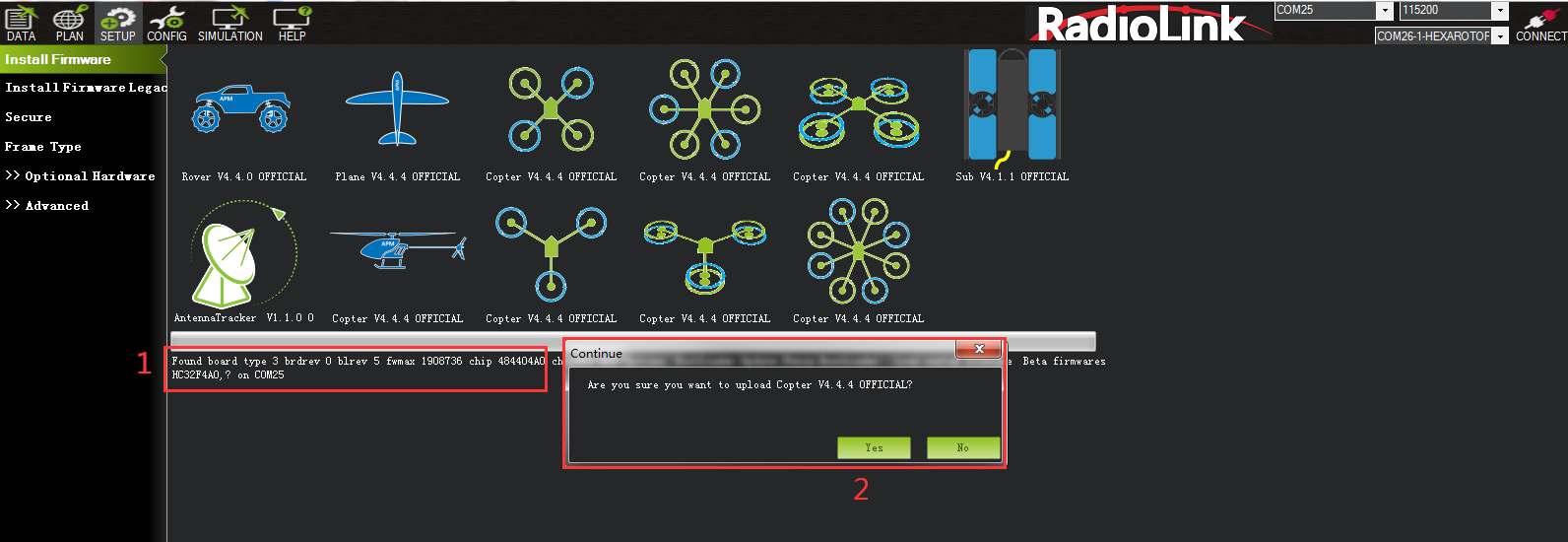
picture ①
picture ②
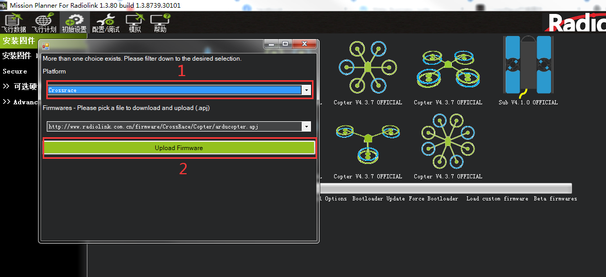
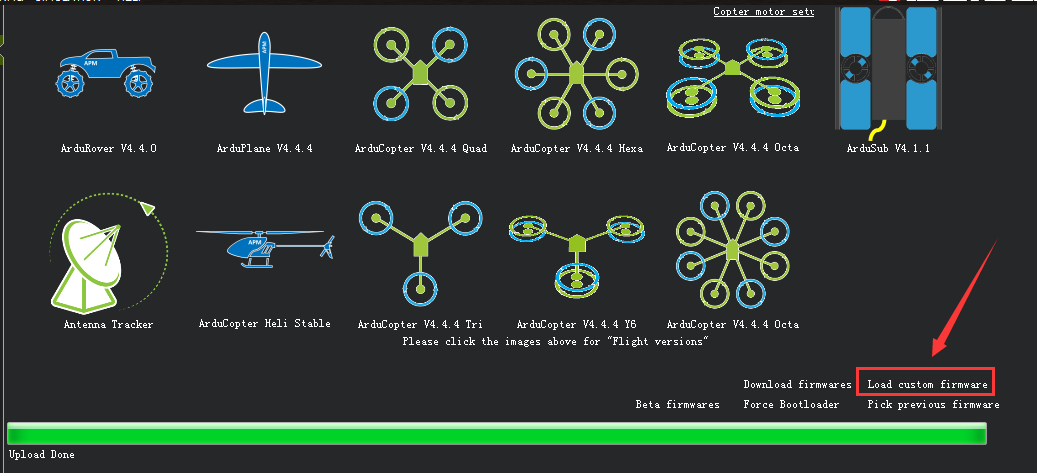
Click Install Firmware Legacy, the right side of the window will automatically download the latest firmware from the network and graphically display the firmware name and the aircraft mode corresponding to the firmware. You only need to click on the picture corresponding to your aircraft mode, Mission Planner will automatically download the firmware from the network. When there is below prompt, click Yes and wait for the firmware to be installed.
The below notice indicates that the flight controller is not recognized. Please unplug the USB cable and plug it back to make sure it is recognized and then click the picture corresponding to your aircraft mode and wait for the firmware to be installed.

After the firmware is installed, select the right COM port and baud rate(Select 115200 for USB wiring baud rate; For telemetry module, select baud rate 57600) and then click “CONNECT” to connect to Mission Planner.
Pay attention:
(1) It needs to take a long time to read the parameters.
(2) There is no option of “Load custom firmware” in Mission Planner.
There’s no Full Parameter List in INITIAL SETUP.
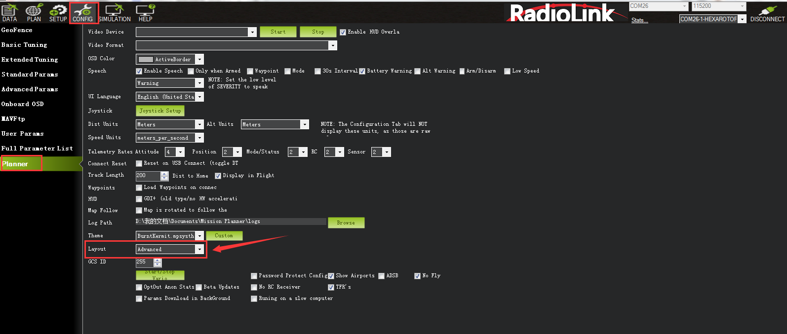
Please set Layout from “Basic” to “Advanced” in CONFIG/TUNING menu if any of the three questions as below encountered when you installing the Mission Planner.
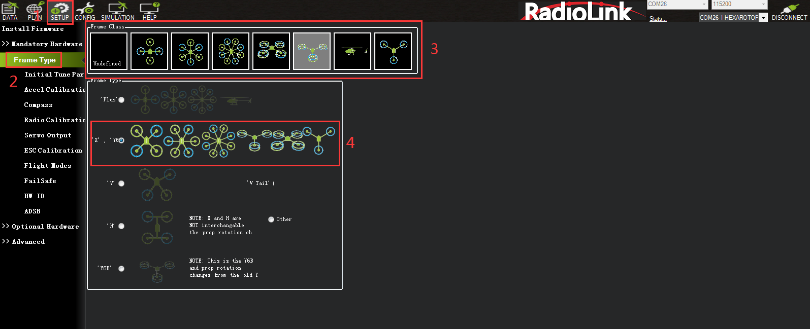
3.2 Frame Type
Please setup as below:
INITIAL SETUP
Mandatory Hardware->Frame Type
Choose Quad or Hexa or other frame types as you need
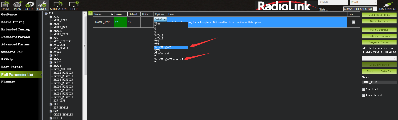
Note: When using a 4-in-1 ESC, you only need to complete the above 3 steps, then search for FRAME_TYPE in Full Parameter List, and select the appropriate value according to your motor installation. If the motor is front mounted (the propellers are on the top), modify the value to 12 (BetaFlightX). If the motor is mounted on the reverse side (the propellers are on the bottom), modify the value to 18 (BetaFlightXReversed) to be compatible with betaflight's motor sequence.
3.3 Accelerometer Calibration
Make sure the CrossRace is keeping horizontal when do the accel calibration.
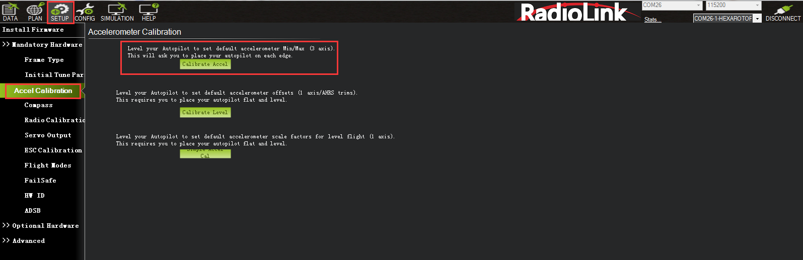
1. Place vehicle level and press any key to save setting.
2. Place vehicle on its LEFT side and press any key to save setting.

3. Place vehicle on its RIGHT side and press any key to save setting.
4. Place vehicle DOWN and press any key to save setting.
5. Place vehicle UP and press any key to save setting.
6. Place vehicle on its BACK and press any key to save setting.
3.4 Compass Calibration
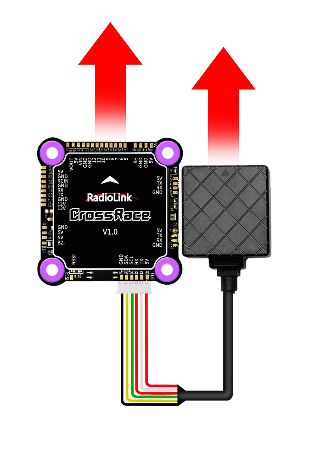
CrossRace does not have a built-in compass. The compass calibration only needs to be done when CrossRace is connected to a GPS.
Calibrate interface will shows as picture below when use with a GPS. Check Use Compass 1.
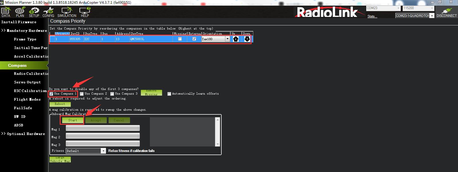
If the GPS mounted with the same direction with flight controller, then it need not to setup the direction of GPS in MP but if you mounted the GPS with the different direction of CrossRace, you have to setup in the MP. Please refer to Chapter 5.1
Please fixed CrossRace and TS100, then click “Start” and turn CrossRace and TS100 till the progress bar of Mag 1 to the end and there will be a prompt: Please reboot the autopilot. Click OK and then reconnect CrossRace to computer, compass calibrate success after restart the CrossRace.
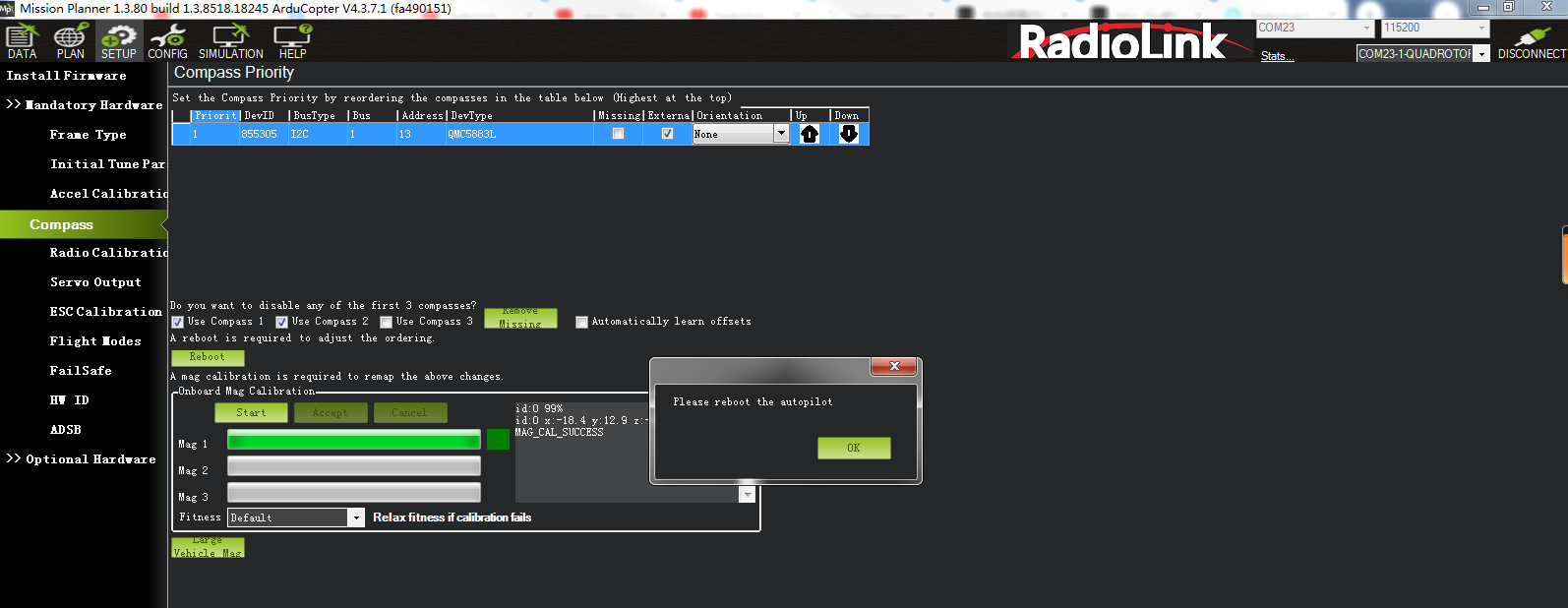
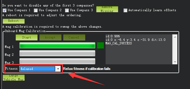
Attention:
When the progress bar moves to 100 and then restart from 0, it may because of the wrong calibrate action or interference. You can have a try to calibrate again till compass calibrate success, or setup the Fitness is Relaxed and recalibrate.
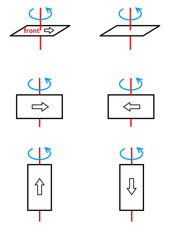
Calibrate the compass as these steps below:
Hold the vehicle in the air and rotate it slowly so that each side (front, back, left, right, top and bottom) points down towards the earth for a few seconds in turn.
3.5 Radio Calibration
You need to connect the receiver first and then you can calibrate the radio. For details on receiver connection, please refer to Chapter 5.2.3.
There are two common stick modes for the transmitter.
Mode 1: left stick controls pitch and yaw, the right stick will control throttle and roll.
Mode 2: left stick controls throttle and yaw; the right stick will control pitch and roll.
Copter default channel mappings are:
Channel 1: Roll
Channel 2: Pitch
Channel 3: Throttle
Channel 4: Yaw
Channel 5: Flight modes
Channel 6: (Optional) In flight tuning or camera mount (mapped to transmitter tuning knob)
Unused channels can be mapped to control additional peripherals.
For safety, you should disconnect the battery and/or remove propellers before preforming radio calibration.
Bind your transmitter and receiver before calibrate radio, connect CrossRace to computer via USB cable and then turn on transmitter. The RC receiver ask to connect to the RC port of CrossRace.
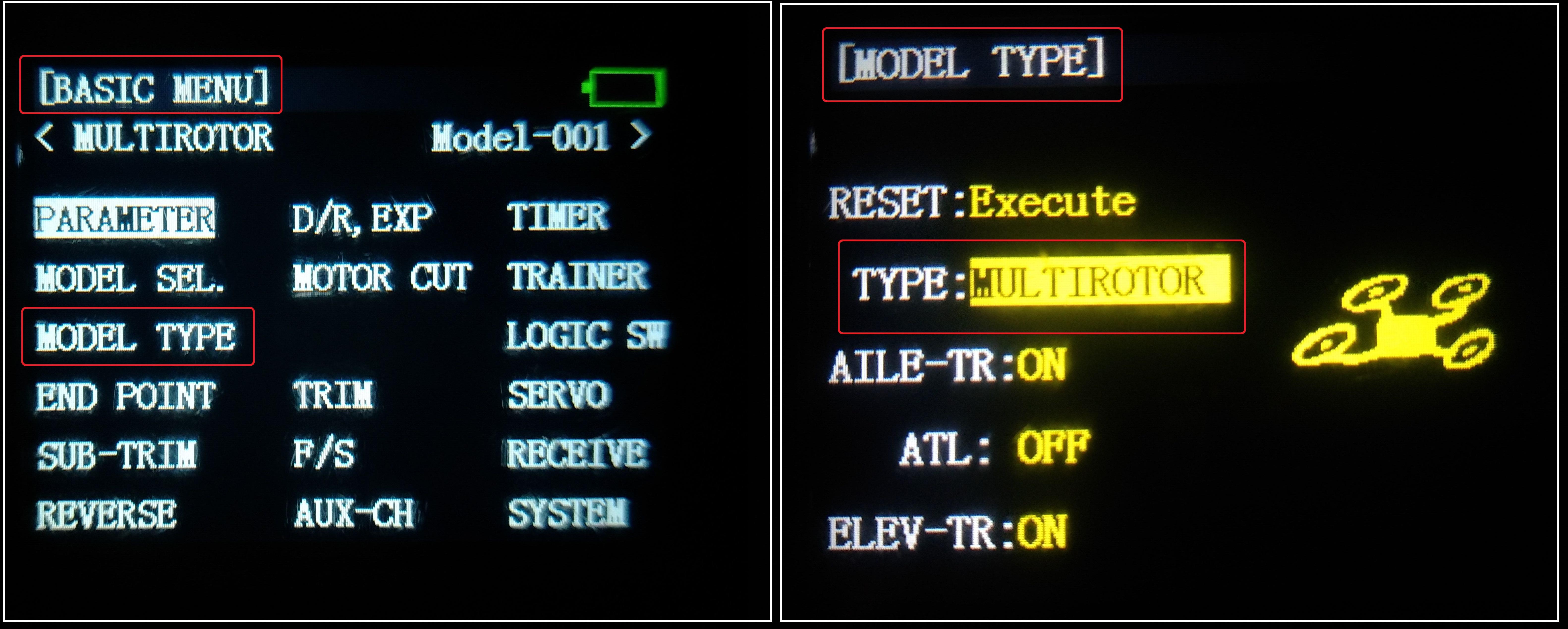
The transmitter will make AT9S as an example in this manual.
1. Press Mode button about one second to into BASIC MENU, and then turn the dial to set MODE TYPE as MULTIROTOR (press Push button 1 second—press Push button again when the display pop-ups “Are you sure?”— you will find out DDD sounds come out with “Please wait…”), the mode type MULTIROTOR have setup success after the DDD sounds have finished.
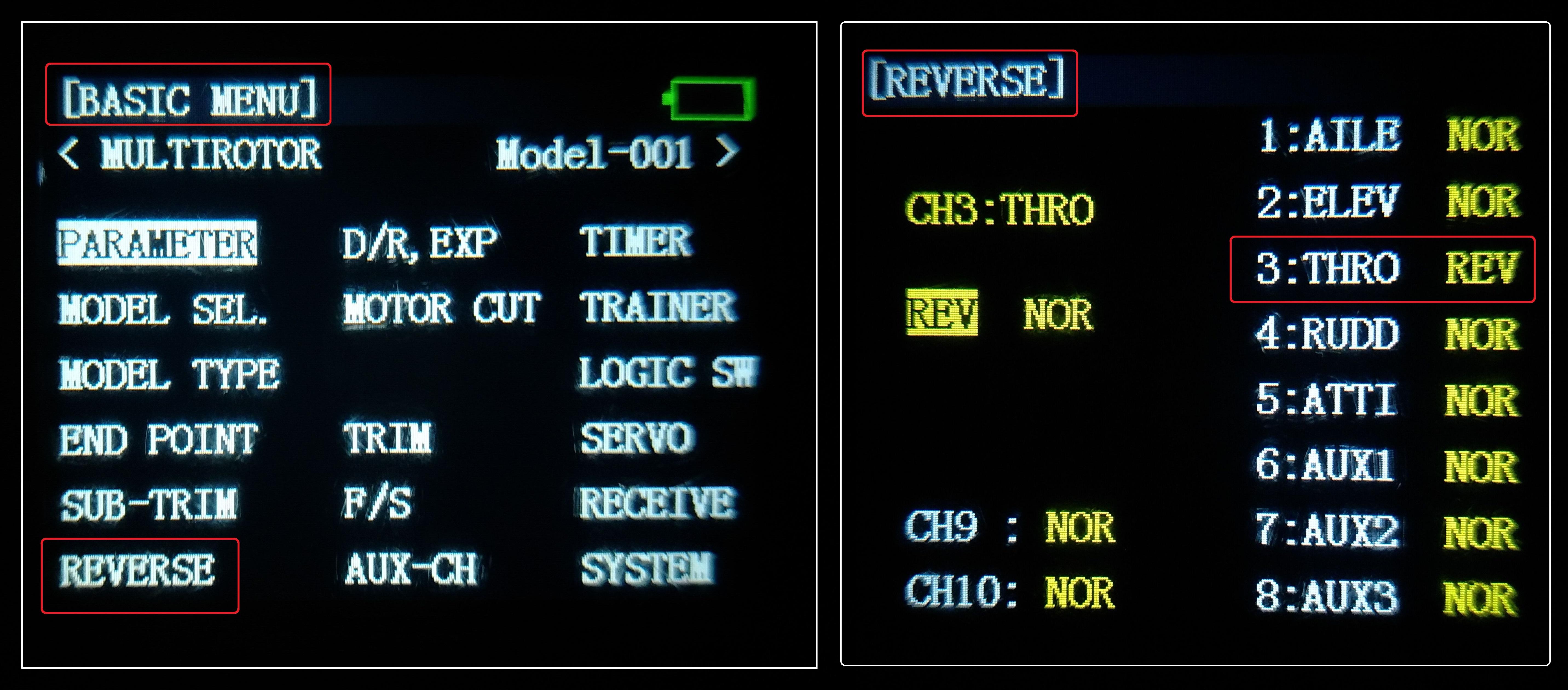
Setup CH3: THRO REV in REVERSE menu (setting steps: Press Mode button about one second to into BASIC MENU, and then turn the dial to choose REVERSE, press Push button to into the REVERSE menu, turn the dial to setup 3: THRO REV, press End to back to Basic menu.
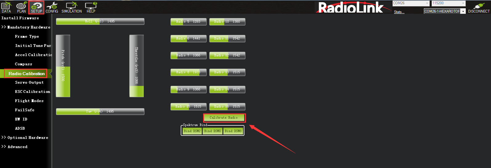
Radio Calibration Steps:
1. Open Mission Planner
2. Choose the right COM and Baud rate
3. Click the CONNECT
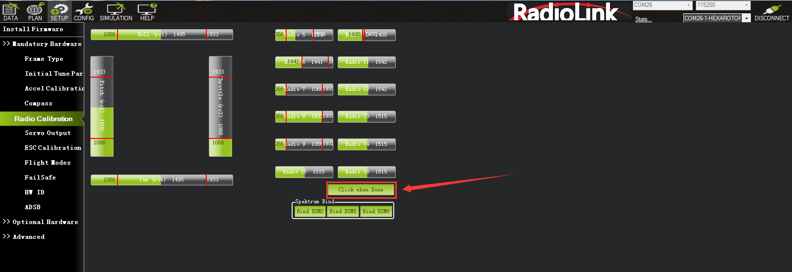
4. Choose INITAIL SETUP—Mandatory Hardware—Radio Calibration
5. Click “Calibrate Radio”
There are two tool pop-ups after you click “OK”, one for make sure both your transmitter and receiver are powered on and connected, and the motor of your drone does not have power and without propellers.
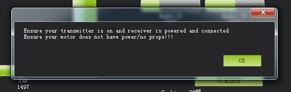
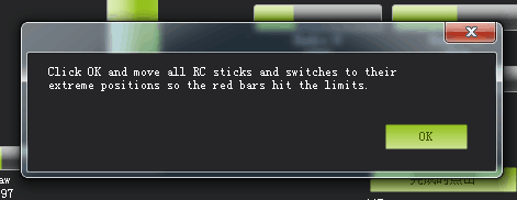
And then click “OK” and move all RC sticks and switches to their extreme positions so the red bars hit the limits.
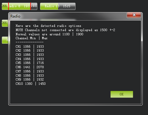
If the red bars have not any change when you move the sticks, please check the receiver have connect success or not, make sure the receiver (maybe R9DS) is output SBUS signal (the blue LED of R9DS means work as SBUS signal). You can check if every corresponding red bar for every channel is work as below:
CH1: low position = roll (towards the left), up position= roll (towards the right).
CH2: low position =pitch(forward), up position =pitch(backwards).
CH3: low position =reduced speed, up position =speed up.
CH4: low position = yaw (towards the left), up position = yaw (towards the right).
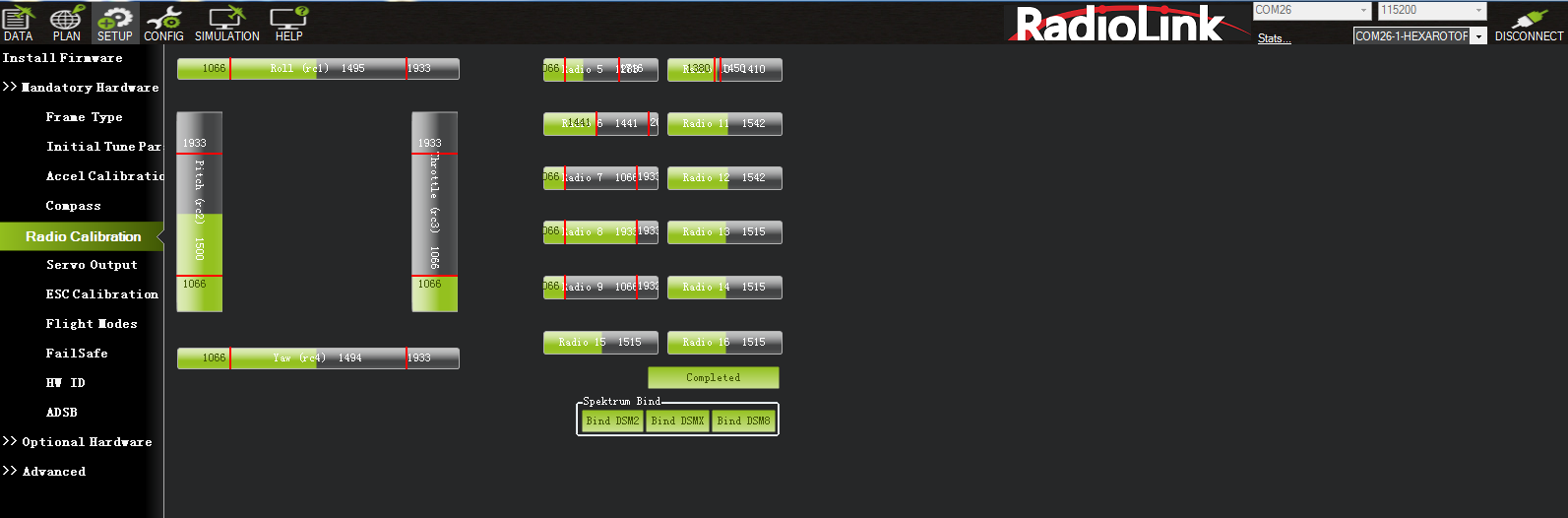
Click OK to save the radio calibration data.
3.6 Flight Modes Setup
CrossRace has many flight modes, and you usually choose six. If the six are not enough, you can also add the assistance of CH7 and CH8, up to eight flight modes.
Flight modes setting steps(Take AT9S Pro as an example):
1. Connect CrossRace and receiver (connect the RC port of CrossRace, and make sure receiver work as SBUS signal).
2. Make sure transmitter bind to receiver success.
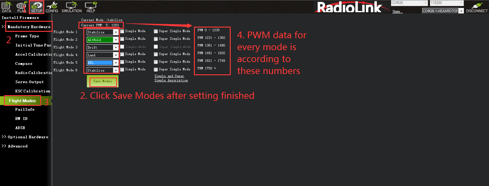
3. Make sure CrossRace connect to Mission Planner success and click INITIAL SETUP—Mandatory Hardware—Flight modes, you can setup the flight modes you want in this menu.
In flight modes menu, it’s very clear that the flight modes, the PWM numerical interval of six flight modes you have set and choose Simple Mode/Super Simple Mode or not.
Most of the RC fans setup the Flight Mode 1 is Stabilize, the other five flight mode will be setup according to users’ flight habit.
First, you have to setup flight mode in transmitter. The setting steps as below:
1. Power on and turn on your transmitter.
2. Press Mode button twice to into ADVANCE MENU, press Push button into ATTITUDE setting menu, CH5 is default to the attitude control channel and please choose a 3 Posi-SW and a 2 Posi-SW to control the attitude. (For the flight mode settings of CH7 and CH8, open Mission Planner---configuration/debugging---extended parameters---Channel 7 opt/Channel 8 opt, and then assign 2 control switches for the two channels in the transmitter. )
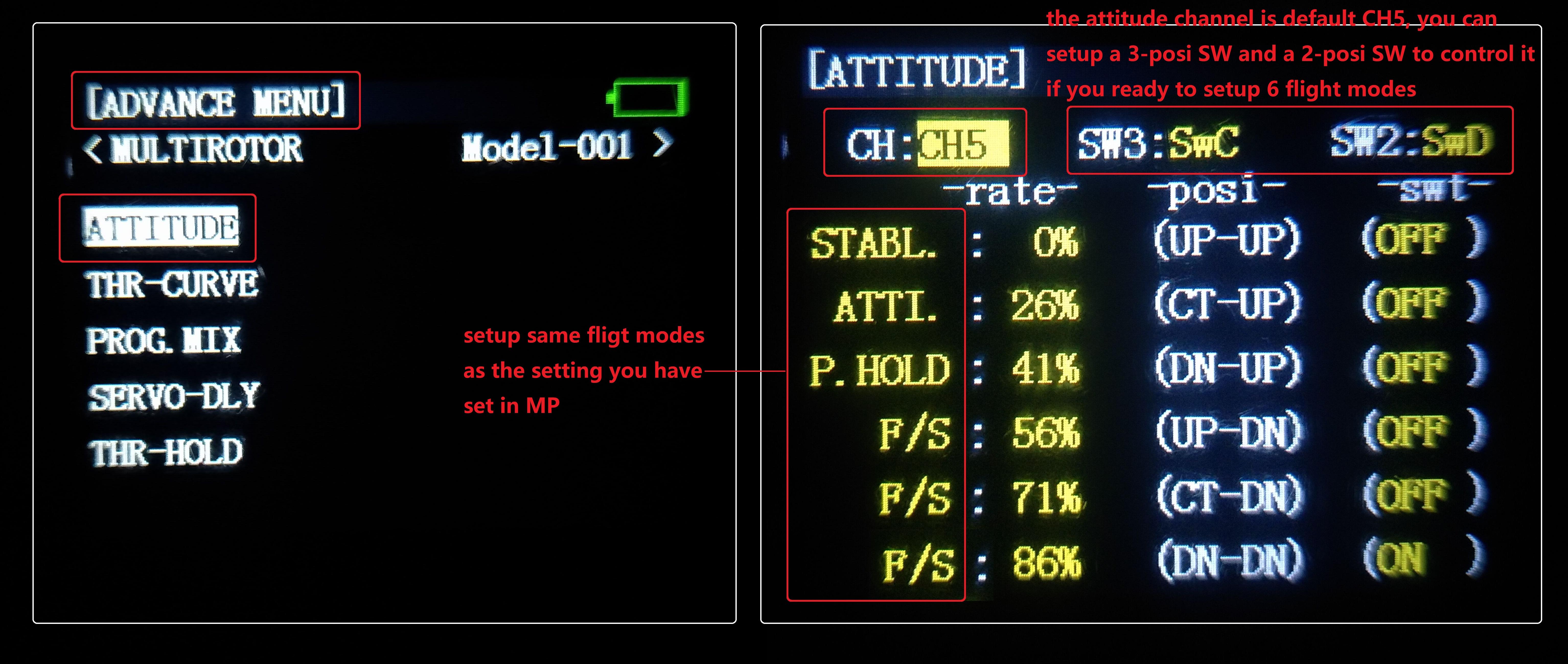
3.Setup Flight Mode 1 is Stabilize both in Mission Planner and transmitter.
Make sure the -swt- is ON (by press the 3 Posi-SW or 2 Posi-SW to make it ON or OFF) and then you can setup the PWM data.
Setup the PWM value according to the default numerical interval (change the value by turn the dial, press the Push button when you choose the right value.)
4. Mode 4 needs a two-way switch. Turn the switch to the corresponding mode. Set it in the same way as step 3.
5. Please check the introduction of simple mode and super simple mode, and then you can choose whether to start simple mode or super simple mode in the mode.
3.7 Flight Modes Introduction
3.7.1 Stabilize Mode
Stabilize mode allows you to fly your vehicle manually, but self-levels the roll and pitch axis.
If you’re learning to fly, try Alt Hold or Loiter instead of Stabilize. You’ll have fewer crashes if you don’t need to concentrate on too many controls at once.
Pilot’s roll and pitch input control the lean angle of the copter. When the pilot releases the roll and pitch sticks the vehicle automatically levels itself.
Pilot will need to regularly input roll and pitch commands to keep the vehicle in place as it is pushed around by the wind.
Pilot’s yaw input controls the rate of change of the heading. When the pilot releases the yaw stick the vehicle will maintain its current heading.
Pilot’s throttle input controls the average motor speed meaning that constant adjustment of the throttle is required to maintain altitude. If the pilot puts the throttle completely down the motors will go to their minimum rate (MOT_SPIN_ARMED) and if the vehicle is flying it will lose attitude control and tumble.
The throttle sent to the motors is automatically adjusted based on the tilt angle of the vehicle (i.e. increased as the vehicle tilts over more) to reduce the compensation the pilot must do as the vehicle’s attitude changes.
Always switch into a manual mode such as stabilize if the autopilot fails to control the vehicle. Maintaining control of your copter is your responsibility.
3.7.2 Acro Mode (FPV)
Acro mode (Rate mode) uses the RC sticks to control the angular velocity of the copter. Release the sticks and the vehicle will maintain its current attitude and will not return to level. Acro mode is useful for aerobatics such as flips or rolls, or FPV when smooth and fast control is desired.
ACRO mode trainer
ACRO_TRAINER setting
0 is disabled. This means the pilot operates in full Rate control with no automatic leveling nor angle-limiting performed by the autopilot.
1 is automatic leveling. The vehicle will automatically return to the level when the pilot releases the sticks. The aggressiveness with which it returns to level can be controlled with the ACRO_BAL_ROLL and ACRO_BAL_PITCH parameters. The default of 1.0 will cause it to return to level at up to 30deg/sec. Higher values will make it return more quickly.
2 is Default to automatic leveling and lean angle limited. Includes the automatic leveling as option #1 but in addition the vehicle will not lean more than 45 degrees (this angle can be configured with the ANGLE_MAX parameter).
The trainer can be enabled/disabled using the Ch7/Ch8 switches. With a 3 position switch the off position (i.e. PWM < 1200) will disable the trainer, middle position will enable option #1 (automatic leveling) and the top position (i.e. PWM > 1800) will enable option #2 (leveling and lean angle limited). With a 2-position switch only options #0 (disabled) and option #2 (leveling & limited) are possible.
Parameters Setting:
ACRO_RP_RATE controls the rotation rate of the roll and pitch axes, by default 360, which represents a rotation rate of 360 degrees/second. Higher values result in higher spin rates, lower values result in lower spin rates.
ACRO_Y_RATE controls the rotation speed of the yaw axis. By default 202.5, like roll and pitch, represents a rotation rate of 202.5 degrees/second.
ACRO_RP_EXPO Acro roll/pitch Expo to allow faster rotation when stick at edges
ACRO_Y_EXPO Acro yaw expo to allow faster rotation when stick at edges
ACRO_EXPO is an amount of Exponential to apply to the pilots stick inputs that only applies to ACRO mode. By default, ACRO mode is much more responsive, even in the center-sticks positions, than the other modes, so this parameter allows the pilot to fine-tune stick response in the control to match what they feel when they are in other modes such as Stabilize, AltHold, PosHold, etc. The default value of 0 applies 30% expo to Roll and Pitch demands from the pilot.
ACRO_OPTION Turn on/off AIR MODE, 0 means turning off AIR MODE, 1 means turning on AIR MODE
ATC_THR_G_BOOST This option can effectively suppress the aircraft's head-up problem caused by pushing the throttle hard. The value ranges from 0-1, and the suppression of the head-up increases from weak to strong. Excessive value will cause the aircraft to oscillate during rapid acceleration. Please adjust according to your own aircraft.
ACRO_THR_MID modifies the ACRO mode throttle center. 0 means turning off the ACRO throttle center, and 1 means turning the ACRO throttle center on.
Warning! If ACRO_THR_MID is set to 1, ACRO mode throttle will be changed into linear throttle. When the aircraft switches from auto-throttle mode (such as AltHold mode, PosHold mode etc.) to ACRO mode, please check whether the throttle stick is in the low position when switching flight modes, If the stick is in the middle position, the aircraft will rush upwards, which may cause dangerous consequences such as loss of control, crash, and casualties.
ATC_THR_MIX_MAN Modifies the priority of throttle and attitude. The larger the value, the higher the attitude priority. The value is usually adjusted to the maximum value of 4 when flying manually.
3.7.3 Altitude Hold Mode
In altitude hold mode, Copter maintains a consistent altitude while allowing roll, pitch, and yaw to be controlled normally. This page contains important information about using and tuning AltHold.
Automatic altitude hold is a feature of many other flight modes (Loiter, Sport, etc.) so the information here pertains to those modes as well.
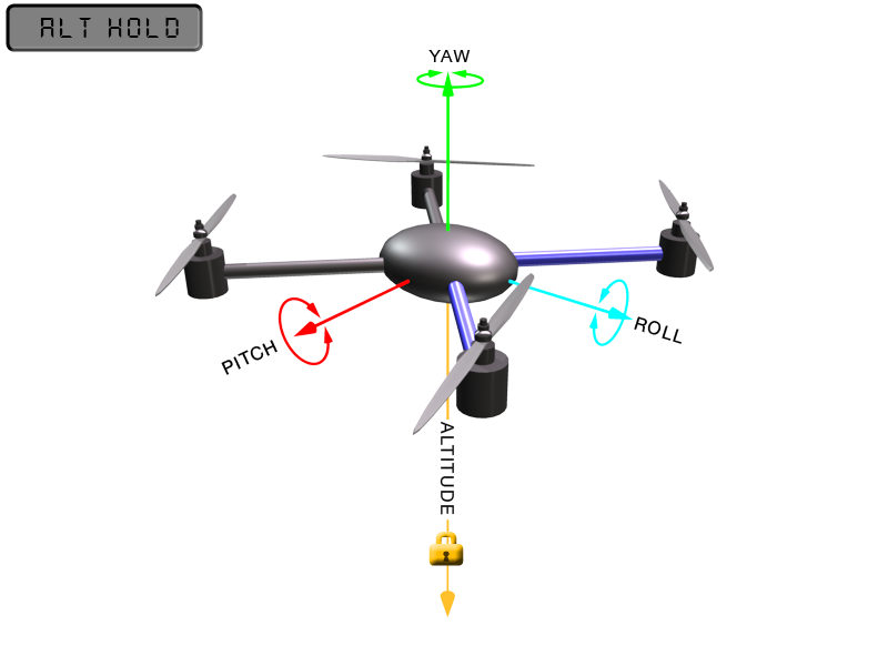
Note: The flight controller uses a barometer which measures air pressure as the primary means for determining altitude (“Pressure Altitude”) and if the air pressure is changing in your flight area due to extreme weather, the copter will follow the air pressure change rather than actual altitude. When fitted and enabled, a downward facing rangefinder such as LiDAR or SONAR will automatically provide even more accurate altitude maintenance, up to the limit of the sensor.
How to control
The pilot can control the climb or descent rate of the vehicle with the throttle stick. If the throttle stick is in the middle (40% ~ 60%) the vehicle will maintain the current altitude. Outside of the mid-throttle dead zone (i.e. below 40% or above 60%) the vehicle will descend or climb depending upon the deflection of the stick. When the stick is completely down the copter will descend at 2.5m/s and if at the very top it will climb by 2.5m/s. The maximum vertical ascending velocity and descending velocity are set by the parameters PILOT_SPEED_UP and PILOT_SPEED_DN respectively.
The size of the deadband can be adjusted with the THR_DZ parameter (AC3.2 and higher only). This params value should be between “0” and “400” with “0” meaning no deadband. “100” would produce a deadband 10% above and below mid throttle (i.e. deadband extends from 40% to 60% throttle stick position).
AC3.1 and later allow arming and disarming in altitude hold mode. When disarming, the copter may need to rest in the landing position for a few seconds to allow the “landing checker” to verify that the copter has landed before you are able to disarm.
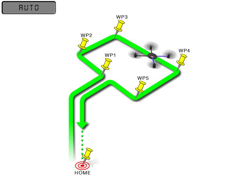
3.7.4 Auto Mode
In Auto mode the copter will follow a pre-programmed mission script stored in the autopilot which is made up of navigation commands (i.e. way points) and “do” commands (i.e. commands that do not affect the location of the copter including triggering a camera shutter). CrossRace multi-rotor firmware can store up to 2617 waypoints, commands and events at one time.
AUTO mode incorporates the altitude control from AltHold mode and position control from Loiter mode and should not be attempted before these modes are flying well. All the same requirements apply including ensuring that vibration levels and compass interference levels are acceptable and that the GPS is functioning well including returning an HDOP of under 2.0.
AUTO should be set-up as one of the Flight Modes on the flight mode switch.
Make sure that the GPS is positioning first:
The LED of CrossRace is green.
The LED of GPS and compass module is blinking.
If starting the mission while the copter is on the ground the pilot should ensure the throttle is down, then switch to the Auto flight mode, then raise the throttle. The moment that the throttle is raised above zero, the copter will begin the mission.
If starting the mission from the air the mission will begin from the first command the moment that the flight mode switch is moved to Auto. If the first command in the mission is a take-off command but the vehicle is already above the take-off command’s altitude the take-off command will be considered completed and the vehicle will move onto the next waypoint.
At any time, the pilot can retake control from the autopilot by returning the flight mode switch to another flight mode such as Stabilize or Loiter. If the pilot then switches to AUTO again, the mission will restart from the first command.
During the mission the pilot’s roll, pitch and throttle inputs are ignored but the yaw can be overridden with the yaw stick. This allows the pilot to for example aim the nose of the copter (which might have a hard-mounted
camera on it) as the copter flies the mission. The autopilot will attempt to retake yaw control as the vehicle passes the next waypoint.
Ending a mission
Missions should normally have an RTL as their final command to ensure the copter will return after the mission completes. Alternatively, the final command could be a LAND with a different location. Without a final RTL or LAND command the copter will simply stop at the final waypoint and the pilot will need to retake control with the transmitter.
Remember that when using RTL, the copter will return to the “home” position which is the location where the copter was armed.
As the copter touches down at the end of the mission the pilot should move the throttle to zero at which point the autopilot will disarm the motors if it also believes that it has landed.
3.7.5 PosHold Mode
The PosHold flight mode (previously known as “Hybrid”) is a new mode for AC3.2. It is similar to Loiter in that the vehicle maintains a constant location, heading, and altitude but is generally more popular because the pilot stick inputs directly control the vehicle’s lean angle providing a more “natural” feel.
When switched on, PosHold mode will automatically attempts to maintain the current location, heading and altitude. Good GPS position, low magnetic interference on the compassand low vibrations are all important in achieving good loiter performance.
How to control
The pilot can control the copter’s location horizontally and vertically with the control sticks.
Horizontal location can be adjusted with the Roll and Pitch control sticks with the default maximum lean angle being 45 degrees (angle can be adjusted with the ANGLE_MAX parameter). When the pilot releases the sticks, the copter will lean back to bring the vehicle to a stop.
Altitude can be controlled with the Throttle control stick just as in AltHold mode
The heading can be set with the Yaw control stick
You may arm in PosHold mode but only once the GPS has 3D lock and the HDOP has dropped to 2.0 or lower.
The HDOP value can be made clearly visible through the mission planner’s Quick screen by double clicking and then selecting “gpshdop” from the large grid of checkboxes.
The maximum brake-angle can be set with the PHLD_BRAKE_ANGLE parameter (i.e. 3000 = the vehicle will lean back up to 30degrees).
The speed the vehicle rotates back to the maximum angle can be set with the PHLD_BRAKE_RATE parameter (i.e. 8 = rotates back at 8 degrees per second)).
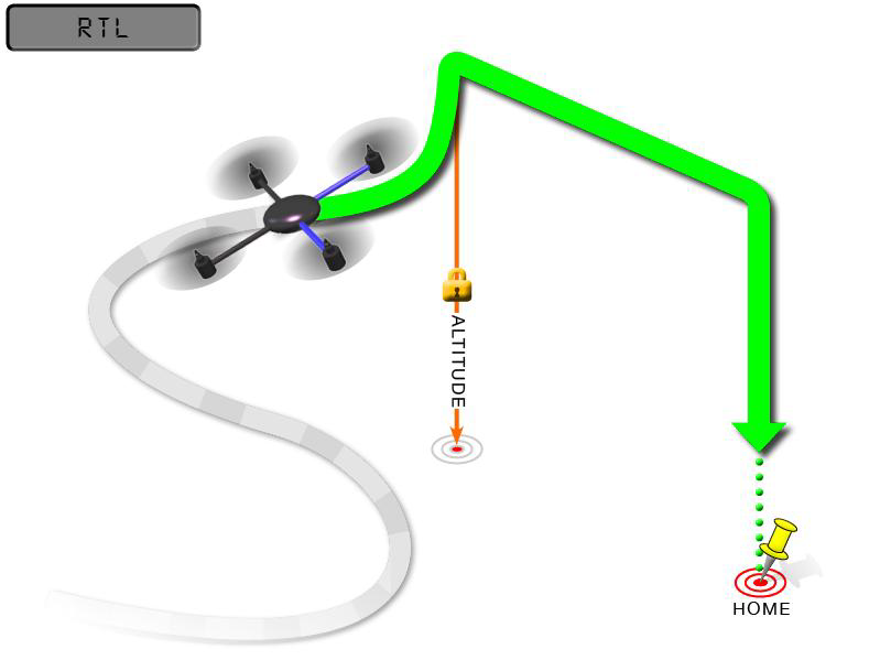
3.7.6 RTL Mode
This very simple flight mode simply stops the vehicle as soon as possible using the Loiter controller. Once invoked, this mode does not accept any input from the pilot. This mode requires GPS.
RTL mode (Return to Launch mode) navigates Copter from its current position to hover above the home position. The behavior of RTL mode can be controlled by several adjustable parameters.
When RTL mode is selected, the copter will return to the home location. The copter will first rise to RTL_ALT before returning home or maintain the current altitude if the current altitude is higher than RTL_ALT. The default value for RTL_ALT is 15m.
RTL is a GPS-dependent move, so it is essential that GPS lock is acquired before attempting to use this mode. Before arming, ensure that the APM’s blue LED is solid and not blinking. For a GPS without compass, the LED will be solid blue when GPS lock is acquired. For the GPS+Compass module, the LED will be blinking blue when GPS is locked.
RTL will command the copter to return to the home position, meaning that it will return to the location where it was armed. Therefore, the home position is always supposed to be your copter’s actual GPS takeoff location, unobstructed and away from people. For Copter if you get GPS lock and then ARM your copter, the home position is the location the copter was in when it was armed. This means if you execute an RTL in Copter, it will return to the location where it was armed.
In RTL mode the flight controller uses a barometer which measures air pressure as the primary means for determining altitude (“Pressure Altitude”) and if the air pressure is changing in your flight area, the copter will follow the air pressure change rather than actual altitude (unless you are within 20 feet of the ground and have SONAR installed and enabled).
Options (User Adjustable Parameters)
1. RTL_ALT: The minimum altitude the copter will move to before returning to launch.
(1) Set to zero to return at the current altitude.
(2) The return altitude can be set from 1 to 8000 centimeters.
(3) The default return altitude Default is 15 meters (1500)
2. RTL_ALT_FINAL: The altitude the copter will move to at the final stage of “Returning to Launch” or after completing a Mission.
(1) Set to zero to automatically land the copter.
(2) The final return altitude may be adjusted from 0 to 1000 centimeters.
3. RTL_LOIT_TIME: Time in milliseconds to hover/pause above the “Home” position before beginning final descent.
The “Loiter” time may be adjusted from 0 to 60,000 milliseconds.
4. WP_YAW_BEHAVIOR: Sets how the autopilot controls the “Yaw” during Missions and RTL.
(1) 0 = Never change Yaw.
(2) 1 = Face Next Waypoint including facing home during RTL.
(3) 2 = Face Next Waypoint except for RTL (i.e. during RTL vehicle will remain pointed at its last heading)
5. LAND_SPEED: The descent speed for the final stage of landing in centimeters per second.
The landing speed is adjustable from 20 to 200 centimeters per second.
6. RTL_CLIMB_MIN: The vehicle will climb at least these many meters at the first stage of the RTL. By default, this value is zero. (only Copter-3.3 and above)
7. RTL_SPEED: The horizontal speed (in cm/s) at which the vehicle will return to home. By default, this value is zero meaning it will use WPNAV_SPEED. (Only Copter-3.4 and higher)
8. RTL_CONE_SLOPE: Defines the slope of an inverted cone above home which is used to limit the amount the vehicle climbs when RTL-ing from close to home. Low values lead to a wide cone meaning the vehicle will climb less, High values will lead to the vehicle climbing more. (Supported in Copter-3.4 and higher)
Notes:
1. Other navigation settings also have an influence over RTL mode:
(1) WPNAV_ACCEL
(2) WPNAV_SPEED_DN
(3) WPNAV_SPEED_UP
2. To use RTL, GPS lock needs to be achieved (Blue GPS LED and Blue APM LED on solid not blinking) before arming and takeoff to establish the home or launch position.
3. Landing and re-arming the copter will reset home, which is a great feature for flying at airfields.
4. If you get lock for the first time while flying, your home will be set at the location of lock.
5. If you set the RTL_ALT to a number at other than 0 it will go to and maintain that altitude while returning.
6. RTL uses WPNAV_SPEED to determine how fast it travels.
7. Once the copter arrives at the home location the copter will pause for RTL_LOIT_TIME milliseconds, timeout (AUTO_LAND), then land.
3.7.7 Simple and Super Simple Modes
“Simple” and “Super Simple” modes can be used in combination with nearly all flight modes except the Acro and Drift (in these flight modes the setting is ignored).
“Simple” and “Super Simple” modes allow the pilot to control the movement of the copter from the pilot’s point of view regardless of which way the copter is facing.
This is useful for new pilots who have not mastered adjusting their roll and pitch inputs depending upon which way the vehicle is facing and for cases when the copter is far enough away that its heading is not apparent.
Simple Mode allows you to control the copter relative to the copters heading at takeoff and relies only on a good compass heading.
Super Simple Mode allows you to control the copter relative to its direction from home (i.e. where it was armed) but requires a good GPS position.
Either mode can be assigned to a particular flight mode switch position or can be enabled/disabled from the Ch7/Ch8 switches.
Normal Mode
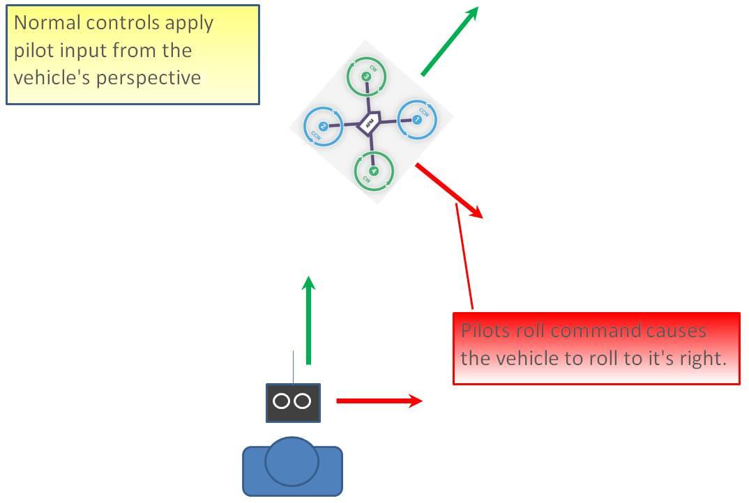
Without Simple or Super Simple enabled, the pilot’s transmitter stick inputs are applied in the orientation of the copter. For example, in the diagram above when the pilot applies roll input right (red) the vehicle rolls to its right.
With the copter is facing in the same direction as the pilot, it is relatively easy to control the vehicle but when the vehicle is facing towards the pilot an inexperienced pilot will feel that the controls are all reversed. I.e. if the pilot inputs right roll, the vehicle will move to the left from the pilot’s point of view.
Simple Modes
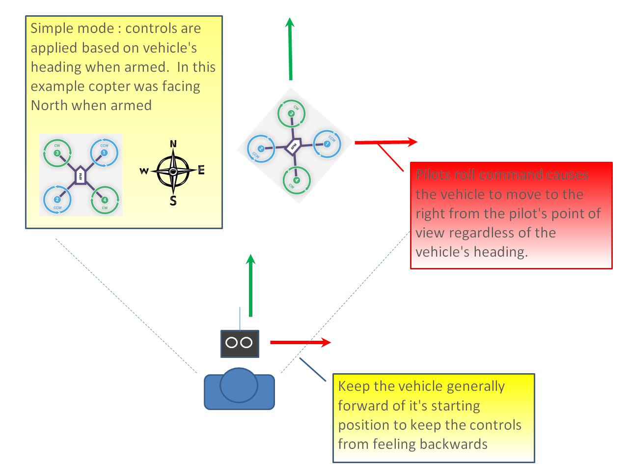
Similar to the “care free” mode on other systems, this mode allows you to fly your copter as though it were pointed in the direction it was pointed when it was armed regardless of its current heading orientation. So, if you hold the pitch stick forward the copter will fly away from you, pull the pitch stick back and it will come back towards home. You can even apply yaw to spin the copter in any direction but the movement of the copter’s position relative to the stick inputs will behave exactly as it did at takeoff.
Generally, when arming you should stand behind the vehicle with its nose pointing directly away from you. While flying you should try to keep the vehicle flying in front of its starting position because if it flies behind you all the controls will feel reversed.
As mentioned above simple mode is also very useful in emergency situations where the copter is far enough away that it is very difficult to determine its heading.
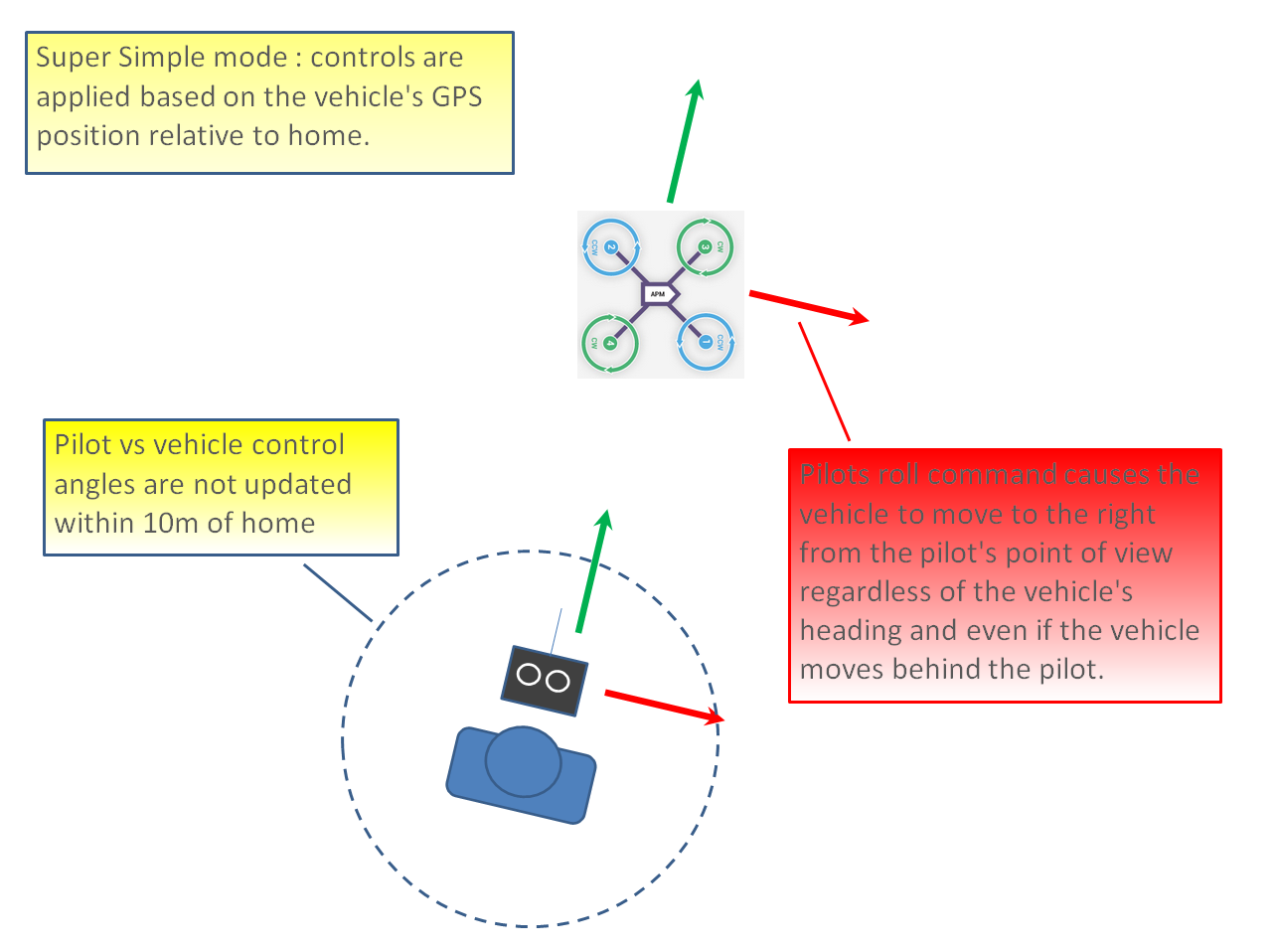
Super Simple Modes
Super Simple mode is the same as simple mode except that it uses the vehicle’s position relative to home instead of the vehicle’s initial heading when it was armed. This means that no matter where the vehicle is, pulling the pitch back will cause it to return towards home regardless of the vehicle’s actual heading.
The advantage over simple mode is that the controls are applied from the pilot’s point of view even when the copter flies behind the pilot/home location.
If the pilot holds full right roll the vehicle will fly a circle clockwise around the pilot (although the circle’s radius may tend to grow slightly with each orbit due to “lag”).
The disadvantage is that mode require a GPS lock because so you should ensure you have GPS lock before take-off.
The orientation is not updated when the vehicle is within 10m of home meaning close fly-bys of the home location should be avoided.
To ensure the controls are correct right at take-off, as with simple mode, you should arm with the pilot standing behind the vehicle and with both pilot and vehicle pointing in the same direction.
3.7.8 More Flight Modes
Guided Mode: Guided mode is a capability of Copter to dynamically guide the copter to a target location wirelessly using a telemetry radio module and Mission Planner application. This page provides instructions for using guided mode.
Loiter Mode: Loiter Mode automatically attempts to maintain the current location, heading and altitude. The pilot may fly the copter in Loiter mode as if it were in a more manual flight mode but when the sticks are released, the vehicle will slow to a stop and hold position.
Circle Mode: Circle will orbit a point located CIRCLE_RADIUS centimeters in front of the vehicle with the nose of the vehicle pointed at the center.
Drift Mode: This page provides tips for flying in Drift Mode and methods for tuning your copter to fly optimally in Drift Mode.
Sport Mode: Sport Mode is also known as “rate controlled stabilize” plus Altitude Hold.
Flip Mode: Vehicle will flip on its roll or pitch axis depending upon the pilot’s roll and pitch stick position. Vehicle will rise for 1 second and then rapidly flip. The vehicle will not flip again until the switch is brought low and back to high. Give yourself at least 10m of altitude before trying flip for the first time!
AutoTune: AutoTune attempts to automatically tune the Stabilize P, Rate P and D, and maximum rotational accelerations to provide the highest response without significant overshoot. Copter needs to be “basically” flyable in AltHold mode before attempting to use AutoTune as the feature needs to be able to “twitch” the copter in the roll and pitch axis.
Land Mode: LAND Mode attempts to bring the copter straight down
Break Mode: This very simple flight mode simply stops the vehicle as soon as possible using the Loiter controller. Once invoked, this mode does not accept any input from the pilot. This mode requires GPS.
Throw Mode: This slightly dangerous flight mode allows the pilot to throw the vehicle into the air (or drop the vehicle) in order to start the motors. Once in the air, this mode does not accept any input from the pilot. This mode requires GPS.
Avoid_ADSB: for ADS-B based avoidance of manned aircraft. Should not be set-up as a pilot selectable flight mode.
Guided_NoGPS: which is meant for developer use only.
The details introduction about flight modes can check on website here:
http://ardupilot.org/copter/docs/flight-modes.html
4. F/S(Fail Safe) Setting
4.1 Radio Fail Safe Setup
CrossRace supports Return-To-Launch in cases where contact between the Pilot’s RC transmitter and the flight controller’s receiver is lost. This page explains this failsafe’s setup and testing. Note the “Radio failsafe” was previously called “Throttle failsafe” because of the way in which some receivers use the throttle channel to signal the loss of contact.
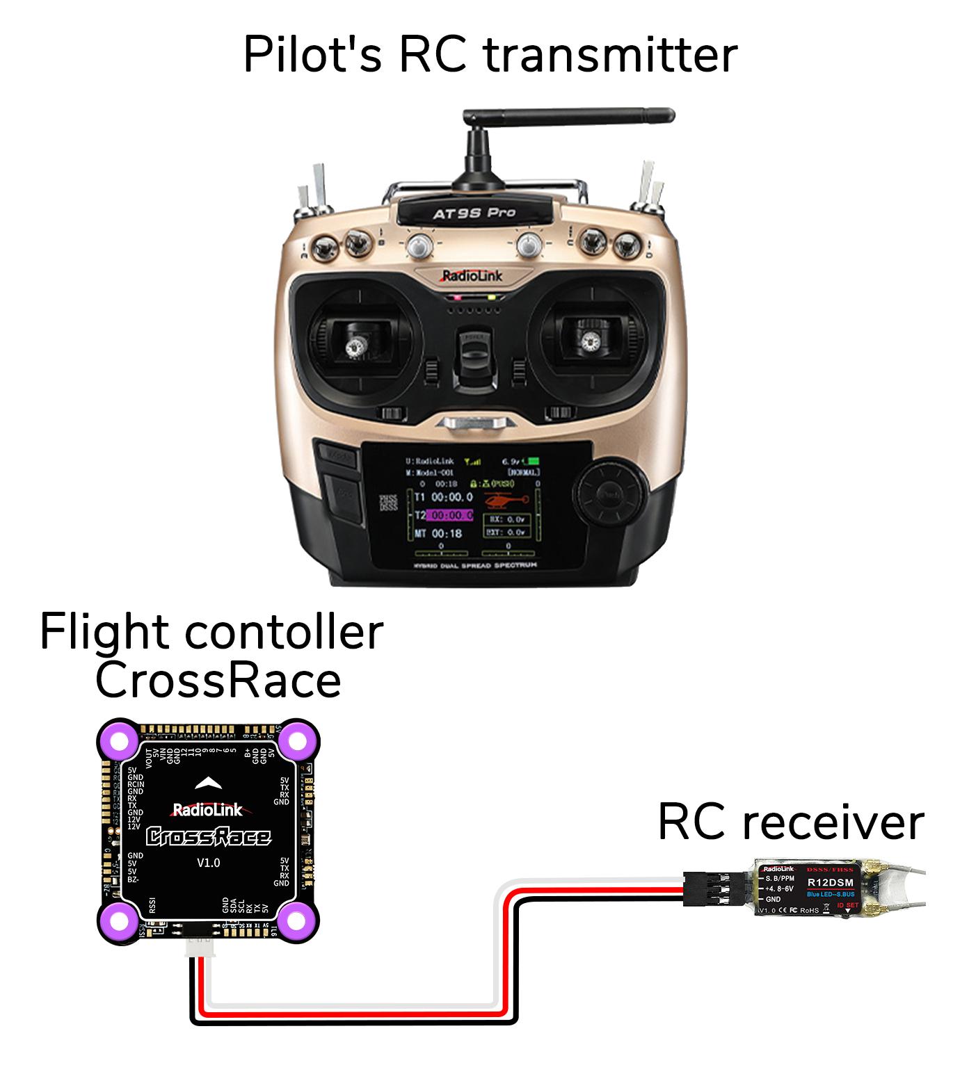
Make sure transmitter and receiver connect success and work with SBUS signal.
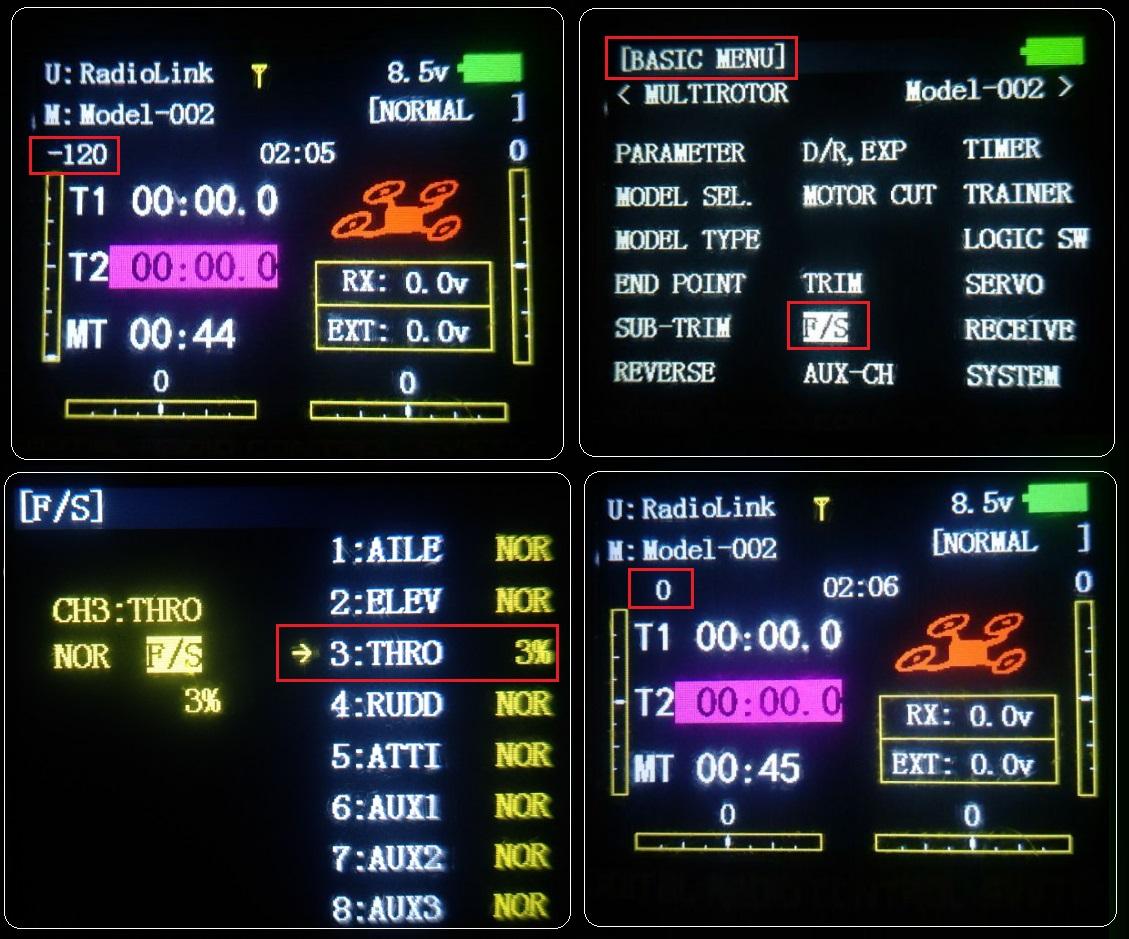
F/S setting steps:
Setup in transmitter: setup the throttle trim to -120 by trim switch and then press Mode button one second into BASIC MENU, choose and into F/S menu, put the throttle stick to the bottom to setup 3: THRO 3%. Please setup the throttle trim back to 0 after setup the THRO 3% success.
Receiver and flight controller CrossRace setup:
By default, a newly purchased receiver will be set-up to simply hold all channels at their last known position when the receiver and transmitter lose contact. This is not good because the flight controller has no way to know that the Pilot has lost control of the vehicle. Instead the receiver must be set-up to signal to the flight controller it has lost contact and there are two ways that it can do this (the method depends upon the receiver):
“Low-Throttle” method - the receiver pulls the throttle channel (normally channel 3) to a value below the bottom of its normal range (normally below 975).
With the LiPo battery disconnected:
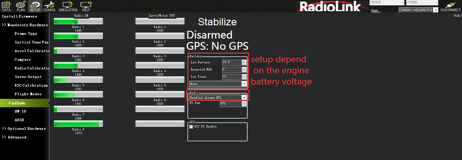
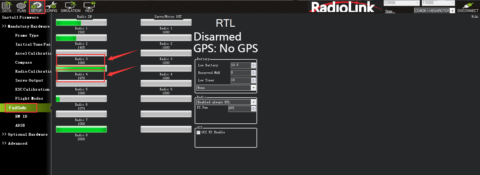
1. Connect your flight controller to the mission planner and select Initial Setup >> Mandatory Hardware >> Failsafe.
2. Set the Failsafe Options to one of the three options:
(1) “Enabled always RTL” to force the vehicle to always RTL even if flying a mission in AUTO mode.
(2) “Enabled Continue with Mission in AUTO” to allow the vehicle to continue with missions even if it takes the vehicle outside of RC range (not recommended). In all other cases the vehicle will RTL.
(3) “Enable always LAND” to force the vehicle to Land immediately if it loses RC contact.
Set the “FS PWM” value to be:
(1) at least 10 PWM higher than your Channel 3’s PWM value when the throttle stick is fully down and the transmitter is off.
(2) at least 10 lower than your channel 3’s PWM value when the throttle stick is fully down and the transmitter is on.
(3) above 910.

Click OK to into the failsafe setting menu.
You can turn off transmitter to check if the Failsafe function setup success(the PWM of CH3 is smaller than 975)
If enabled and set-up correctly the radio Failsafe will trigger if:
(1) The pilot turns off the RC transmitter.
(2) The vehicle travels outside of RC range.
(3) The receiver loses power (unlikely).
(4) The wires connecting the receiver to the flight controller are broken (unlikely).
1. Set battery fail safe
Set battery fail safe according to the aircraft power consumption, battery voltage, and flight distance. When the battery voltage is lower than this value, there will be enough battery voltage to return the aircraft. Set the low battery value (This value is set according to the battery voltage. When you fly long distances, Please set the single cell to 3.8V, the voltage value is 3.8V*S, the 3S battery is 3.8*3=11.4V; when at a close distance, you can set 3.6V for each cell), and set the action to RTL (return to home).
2. Set the radio fail safe( throttle fail safe). Set the action to RTL , and set the fail safe PWM (generally no need to change). Set the fail-safe setting in the transmitter, because we set the fail safe to start after the throttle is lower than 975, so we need to set the throttle fail safe value. Push the throttle trim button in the transmitter and check the input value of channel 3 in the transmitter in fail safe, so that the value is less than 10 or more than 975. Take RadioLink AT9S Pro as an example. Press the Mode button to enter the basic menu and select FAIL SAFE. Press Push to select Channel 3: Throttle. Turn the dial to select F/S and press Push button. When a value appears, the setting is successful. Remember to turn trim button to restore.
When a radio Failsafe is triggered one of the following will happen:
Nothing if the vehicle is already disarmed.
Motors will be immediately disarmed if the vehicle is landed OR in stabilize or acro mode and the pilot’s throttle is at zero.
Return-to-Launch (RTL) if the vehicle has a GPS lock and is more than 2 meters from the home position.
LAND if the vehicle has no GPS lock OR is within 2 meters of home OR the FS_THR_ENABLE parameter is set to “Enabled Always Land”
Continue the task if in automatic mode and the failsafe option is Enabled_continue_in_auto_mode.
If the failsafe is cleared (the throttle is above 975), the aircraft will continue to fly in the flight mode corresponding to the previously set failsafe, and will not automatically return to the previous flight mode of normal flight.
For example: the RTL mode is set for the fail safe, and the aircraft is flying normally in stabilize mode. Suddenly the fail safe is triggered due to signal loss, causing the aircraft's flight mode to automatically change from the stabilize mode to the previously set RTL mode. Even if the transmitter and receiver signals are reconnected during the return journey and the fail safe is released, the aircraft will still fly in the RTL mode. If you need to fly in stabilize mode again, you need to move the flight mode switch to another position and then back to the position of stabilize mode.
Set attitude fail safe in the transmitter. The prerequisite for setting attitude fail safe is that there is a fail safe mode in the flight mode settings. Taking RadioLink AT9S Pro as an example. Turn on the transmitter, flip the setting switch to RTL mode or the fail-safe mode you want to set, press Mode to enter the basic menu, select fail-safe, press Push to select 5: Attitude, Toggle to select F/S, hold Push, and the numbers below will change. Open Mission Planner to verify it. Turn off the transmitter and check that it is RTL in Mission Planner.
4.2 EKF Fail Safe
FS_EKF_ACTION
Note: This parameter is for advanced users.
Controls the action that will be taken when an EKF failsafe is invoked.
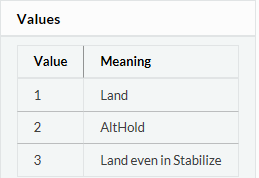
It defaults the value 1, that is the drone will land if lose signal, but you can change the setting from value 1 to value 2, which means the drone will AltHold if lose signal.
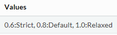
FS_EKF_THRESH
Note: This parameter is for advanced users
Allows setting the maximum acceptable compass and velocity variance
5. Hardware Setup
Prepare a drone first, a X frame quadcopter as a sample, please mount a CrossRace as below steps after you have assembled the drone.
1. Mount a CrossRace on the center position of the drone, and make sure that the CrossRace is horizontal on the drone.
2. Connect the Mission Planner after download the firmware, calibrate and setup parameters as the steps above.
3. Arm it. If the arm can be done, fly the aircraft after installing the propellers; if arm can be done, find the problem of setting or calibration and solve it.
Note: When calibrating the ESC (first flight), please remove the propellers.
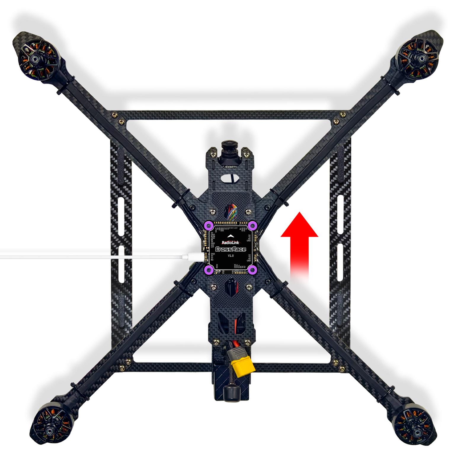
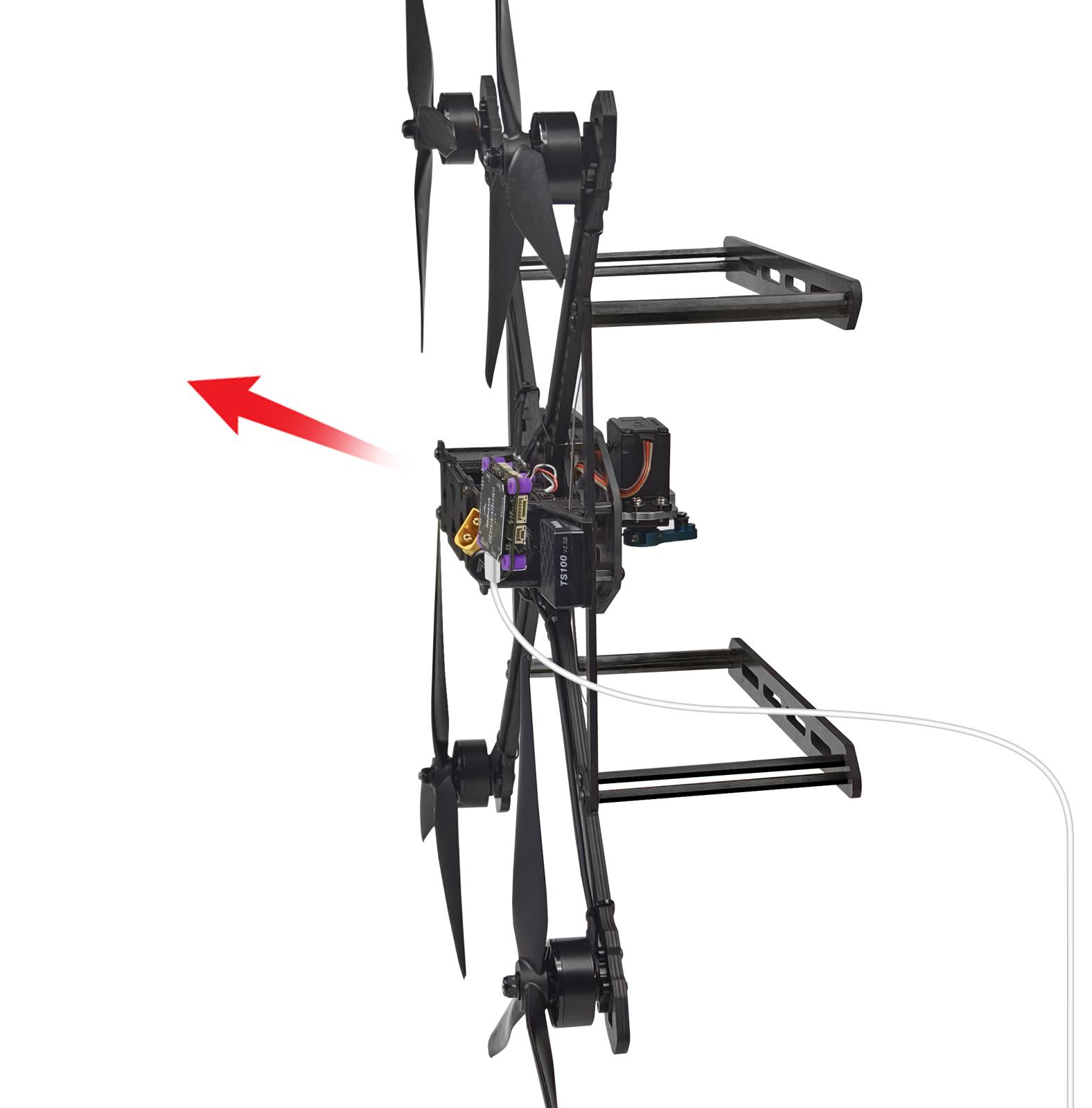
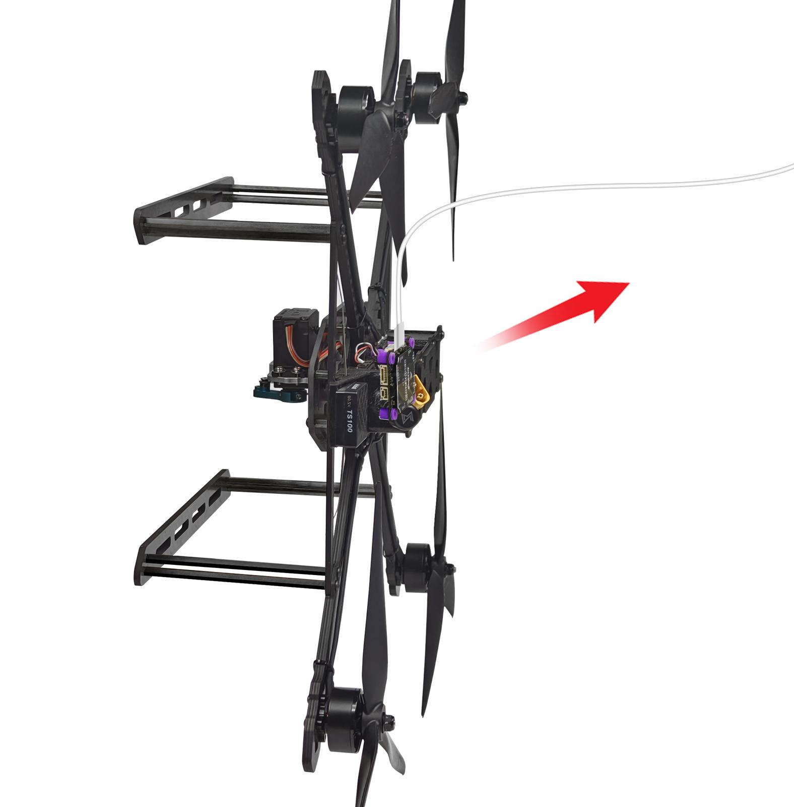
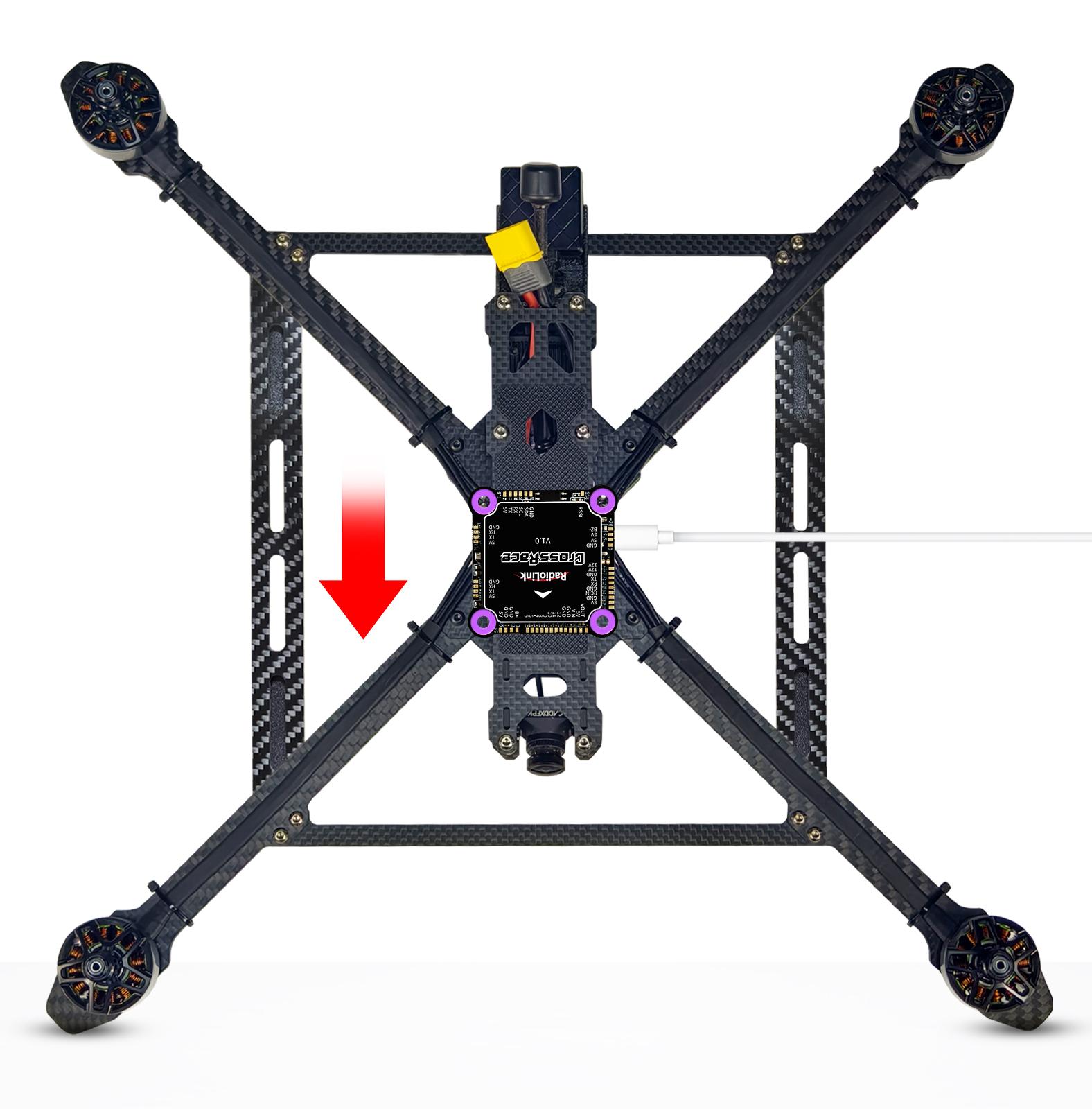
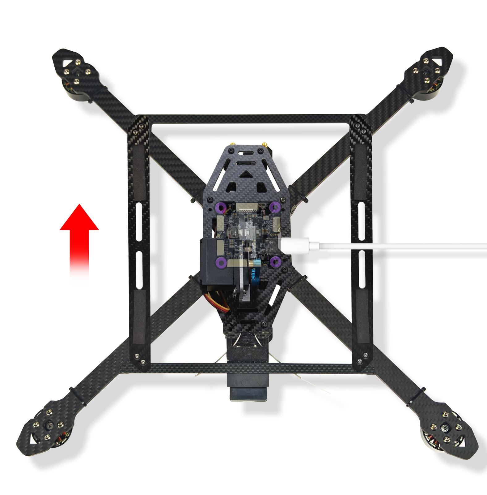
5.1 Install CrossRace on the Aircraft
CrossRace is mounted with with fly tower installation method. Install a shock-absorbing rubber sleeve on the mounting hole and insert CrossRace into the fly tower mounting position. Make sure the arrow of the CrossRace is point to the front.
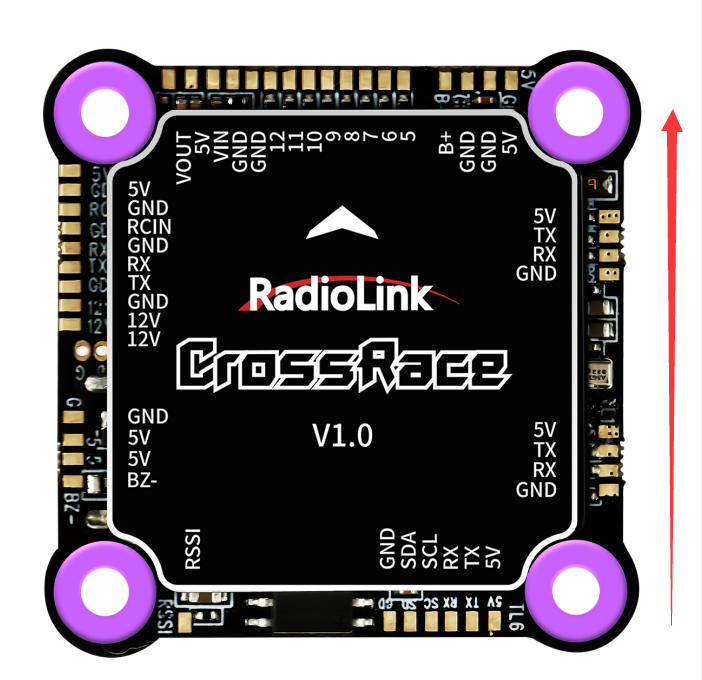
Keep the GPS with the same direction of CrossRace if you need to use CrossRace with GPS.
If the installation can’t be done with the default direction, parameters need to be setup according to the installation direction.
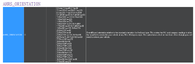
Set the rotation direction and degree and the corresponding values basing on the variation of the flight controller and the aircraft vehicle and input to save. Restart and test if the movements of the flight controller are correct at the homepage of Mission Planner.
5.2 Connect CrossRace to the Aircraft
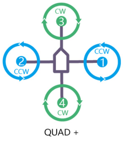
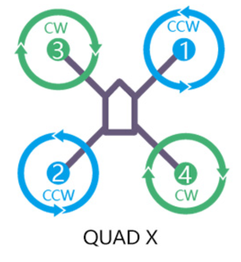
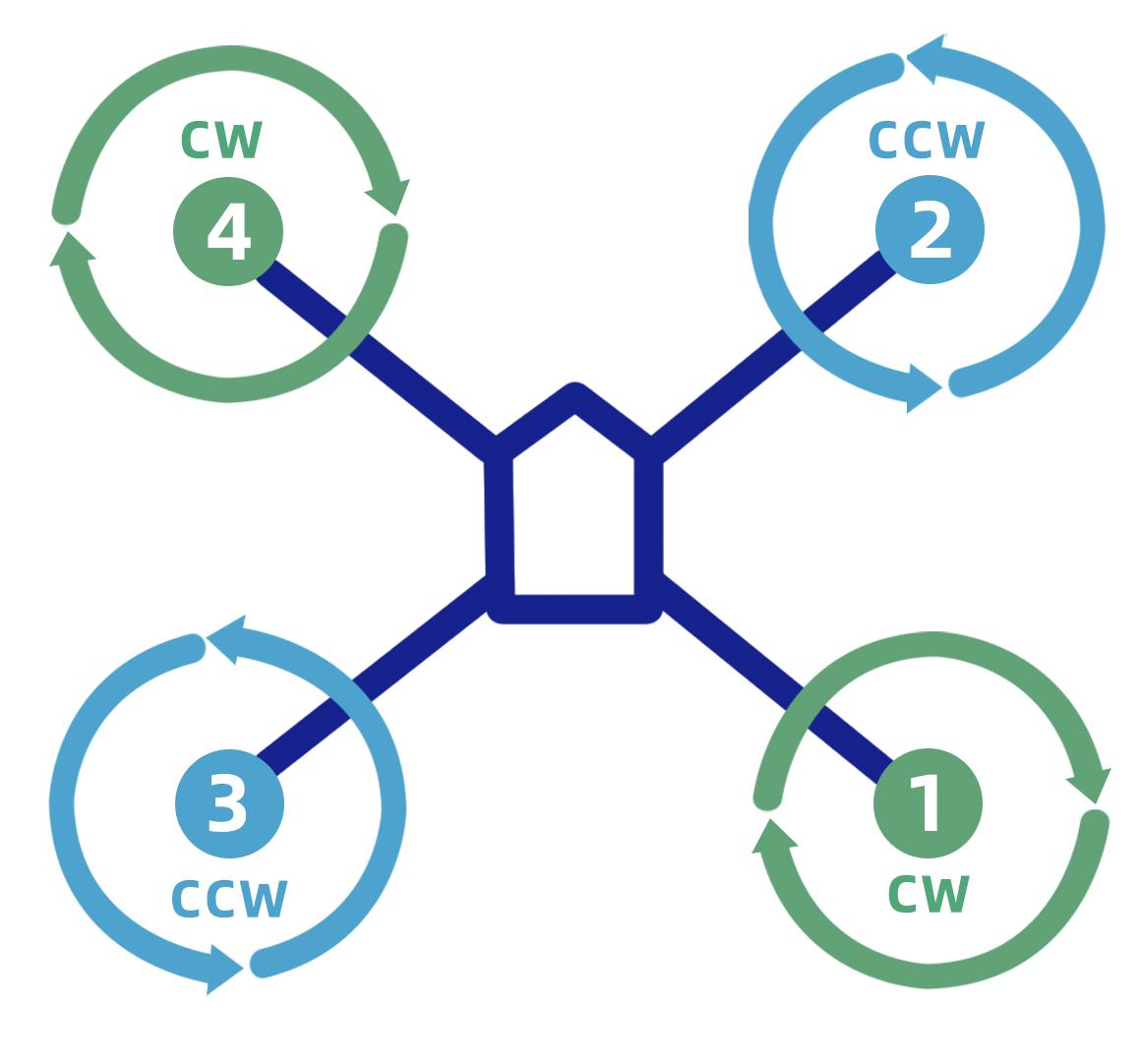
5.2.1 Motor Order Rotation Select
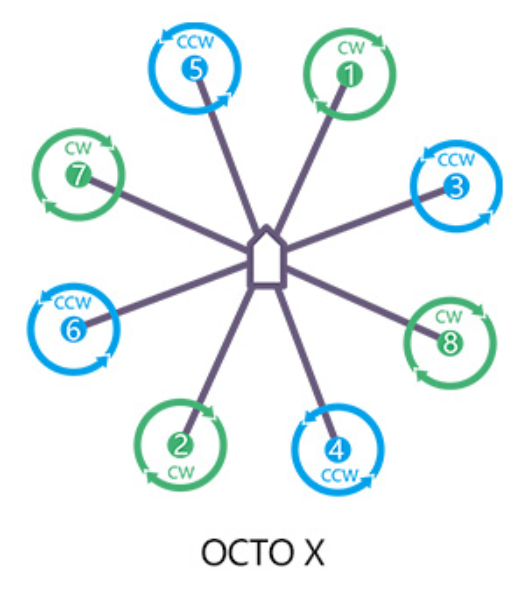
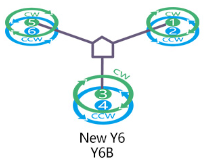
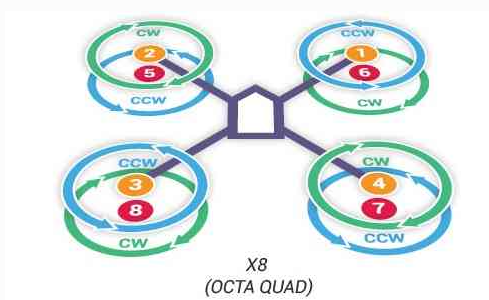
Green means CW
Blue means CCW
Legend for motor-order diagrams
Quadcopters
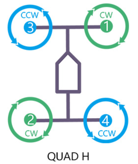
Note: When the rack type is BetaFLightX/BetaFlightXReversed, the motor sequence is as follows:
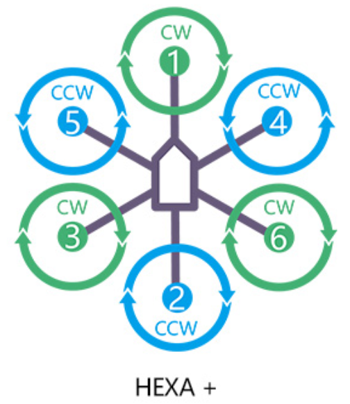
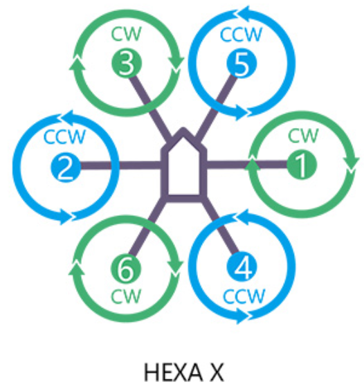
Hexacopter
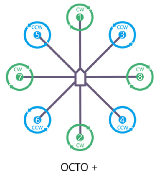
Octocopter
Y6

X8
Tricopter
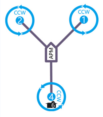
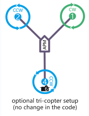
Note Since there’s no voltage output from the flight controller, an extra BEC module needs to be connected to power supply servo for this model frame .
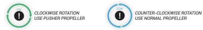
5.2.2 How to Recognize Clockwise and Counterclockwise Propellers
There are clockwise propellers and counterclockwise propellers. The high side of the propeller points in the direction of rotation. The propeller that rotate clockwise are CW propellers, and the propeller that rotate counterclockwise are CCW propellers.

CCW propellers (counterclockwise rotation)
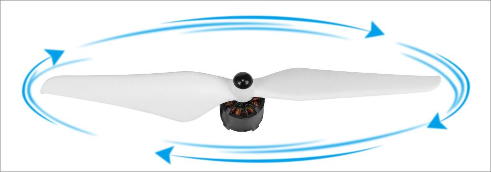
CW propellers (clockwise rotation)
5.2.3 Connect the Spare Parts
Receiver installation:
CrossRace supports receivers with SBUS/PPM signal and serial port receivers.
Using receivers with SBUS/PPM signal.
There are two ways to connect the receiver.
Use the included 3pin cable to connect to the RCIN interface of the flight controller, and plug the other end into the receiver.
You can also choose to weld the SBUS/PPM signal line of the receiver to the RCIN pad of the flight controller.
Using serial port receiver (ERLS, Black Sheep 915 receiver, etc.).
There are also two ways to connect the serial port receiver.
Use the included 4-pin cable to connect to the telem1 or telem2 interface of the flight controller, and connect the other end to the receiver. Note that the RX port on the flight controller is connected to the TX port of the receiver, and the RX on the flight control section is connected to the TX port of the receiver. The TX port on the flight controller is connected to the RX port of the receiver.
You can also weld the receiver to the flight controller. The corresponding pads are drawn from the back of the interfaces of telem1 and telem2, and you can just solder them directly.
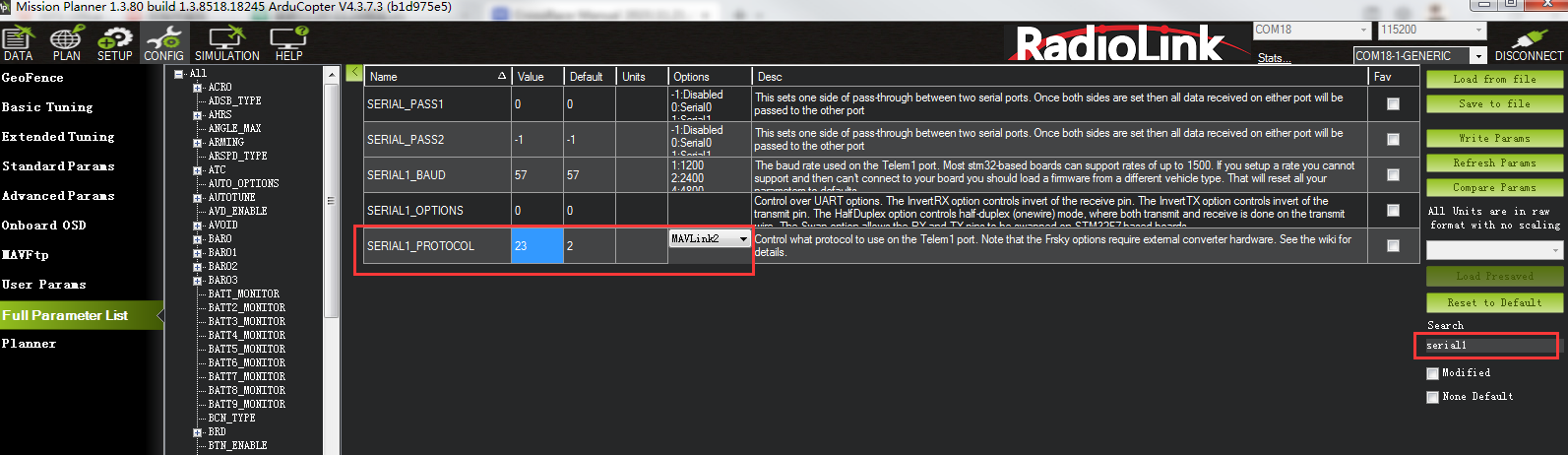
After the connection, enter Mission Planner. Search for SERIALx_PROTOCOL in Full parameter List (x depends on the selected serial port number. If serial port 1 is selected, search for SERIAL1_PROTOCOL), change the value to 23 (RCIN). Save the parameter and restart the flight controller.
Buzzer installation:
Directly solder the negative electrode of the buzzer to the BZ- pad and the positive electrode to the 5V pad.
Image transmission installation:
Use analog image transmission:
When using analog image transmission, you only need to connect the video output of the camera to the VIN port of the flight controller, and VOUT to the image transmission. No need to set the parameters.
Use digital image transmission:
CrossRace supports many digital image transmission such as DJI O3 air unit, DJI VISTA air unit, Walksnail AVATAR air unit, etc.
When using the DJI VISTA air unit, connect it directly to the digital image transmission interface, and modify the following configuration in Mission Planner:
1: Search for OSD_TYPE in Full Parameter List and change the parameter to 3 (MSP).
2: Save and restart flight controller.
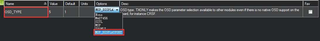
When using the DJI O3 air unit, connect it directly to the digital image transmission port, and modify the following configuration in Mission Planner:
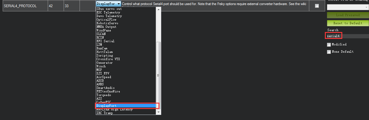
1: Search for SERIAL4_PROTOCOL in Full Parameter List and change the parameter to 42(DISPLAYPORT).
2: Search for OSD_TYPE in Full Parameter List and change the parameter to 5 (MPS_DISPLAYPORT).
3: Save and restart flight controller.
When using the Walksnail AVATAR air unit, connect the interface to the last 4 pins of the digital image serial port (12v G TX RX), and modify the following configuration on the Mission Planner:
1: Search for SERIAL4_PROTOCOL in Full Parameter List and change the parameter to 42(DISPLAYPORT).
2: Search for OSD_TYPE in Full Parameter List and change the parameter to 5 (MPS_DISPLAYPORT).
3: Save and restart flight controller.
Battery Monitor Setup
Mission Planner Setup
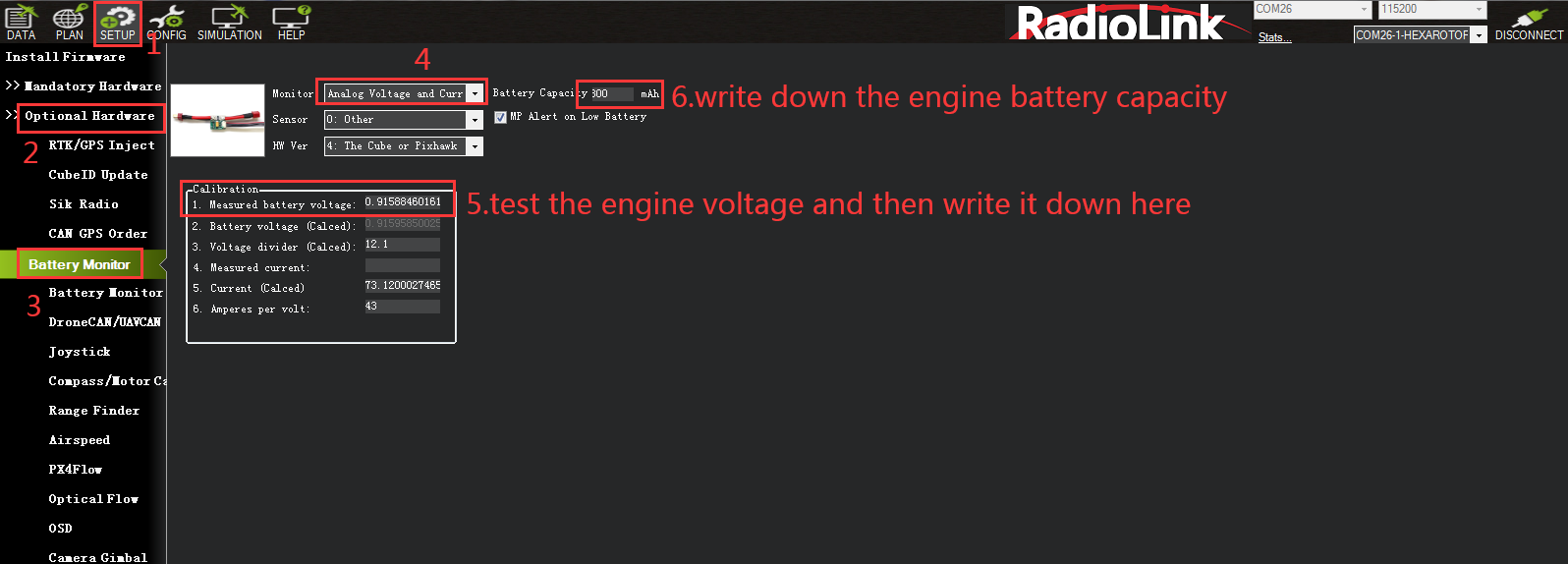
Battery measurement is primarily set up in the Mission Planner ‘s INITIAL SETUP -- Optional Hardware -- Battery Monitor screen.
Enter the properties your module can measure, the type of module, the type of flight controller, and the battery capacity:
Monitor: Voltage and Current or Battery Volts.
Sensor: Supported power module, or “Other”.
APM ver: Flight controller (e.g. Pixhawk ).
Battery Capacity: Battery capacity in mAh.
When the setting is turned on, please disconnect the flight controller, power on the flight controller again, then open this interface and enter the measured battery voltage. When the voltage that appears in the 2 battery voltage (calculated) box is the same as the entered measurement value and no longer jumps, it means the setting is normal.
Note: When the setting is inaccurate, it may be impossible to arm, or the buzzer may beep quickly after arming. This means that the power supply is not set incorrectly. Please set it correctly again. If there is a continuous fail safe situation, it is possible that the battery low-voltage fail safe is turned on and the battery monitoring is inaccurate.
5.3 LED Indicator, Arming and Troubleshooting
5.3.1 LED Indicator
Blue and red flashing: Initializing
Yellow flashing twice: Error, Arming rejected
Blue flashing: Stabilize, can be armed. Faile to RTL or PosHold
Green flashing: GPS locked, can be armed and take off, RTL
Green always on + a long D sound: Armed and ready to take off
Yellow flashing: Transmitter failsafe activated
Yellow flashing+repeated sounds: Battery failsafe activated
Yellow flashing+High/High/Low sounds: GPS data error or GPS failsafe activated
5.3.2 Arming and Disarming
When your the LED of the flight controller is blue or green, you can arm it. When the LED is yellow, you can also perform arming and check the cause of the fault.
Arm action:
Use the left joystick to perform the arm action shown below (The stick mode is mode 2):
 Hold it for 5 seconds;
3. When you hear the buzzer beeping for a long time and the flight controller indicator light is always on, the arming is successful.
Note:
When the stick mode of the transmitter is not mode 2, please make sure Channel 3 is at the lowest and channel 4 is at the highest to perform arming. You can check the action in Mission Planner.
In the above picture, Channel 3 is at the lowest and channel 4 is at the highest.
2. If the buzzer beeps when the arming action is performed, the arming fails. Please connect the flight controller to Mission Planner to check the disarm prompt, and solve the fault according to the fault instructions in Chapter 5.3.4 .
 Disarm action: Hold the left joystick to perform the arm action shown below for 5 seconds. (The stick mode is mode 2). When the LED of flight controller flashes and propellers stop rotating, the disarming is successful.
Note:
1. When the stick mode of the transmitter is not mode 2, please make sure Channel 3 is at the lowest and channel 4 is at the lowest to perform disarming.
2. In GPS-assisted mode such as Alt-Hold mode, PosHold mode and Loiter mode, please wait for the propeller to stop before performing the disarming action, otherwise the aircraft may flip over.
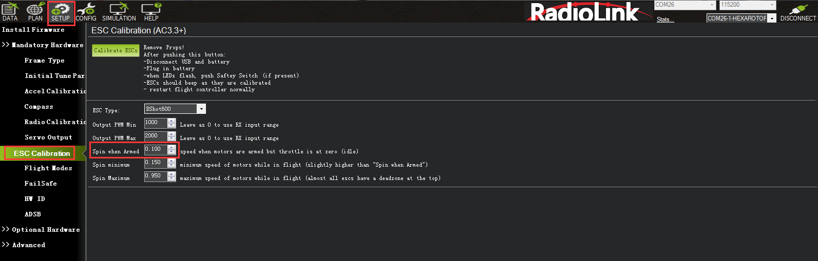
5.3.3 Turn off Spinning when Armed
If you connect the battery and armed, the motors begin to have speed even though the throttle is at zero. It reminds you that CrossRace is in service and please take care of the safety. This function is very importance for the safety but if you do not want use this function, you can turn off it.
How to turn off this function:
Setup the number of Spin when Armed from 0.100 to 0.000 as the picture below.
5.3.4 Troubleshooting for Arm Failure
Pre-Arm Safety Checks:
Radio calibrated
Accelerometers calibrated
Compass healthy
Compass offsets
Compass calibrated
Compass Field length
Barometer healthy
Geofencing & GPS lock
Board Voltage
For more details of Pre-arm safety check, please refer to the link:
https://ardupilot.org/copter/docs/common-prearm-safety-checks.html
When the arming fails, the flight controller LED indicator flashes yellow, perform arming action, and the buzzer prompts. Connect the flight contrroller to Mission Planner to view the fault prompt. After connecting, view the following interface:
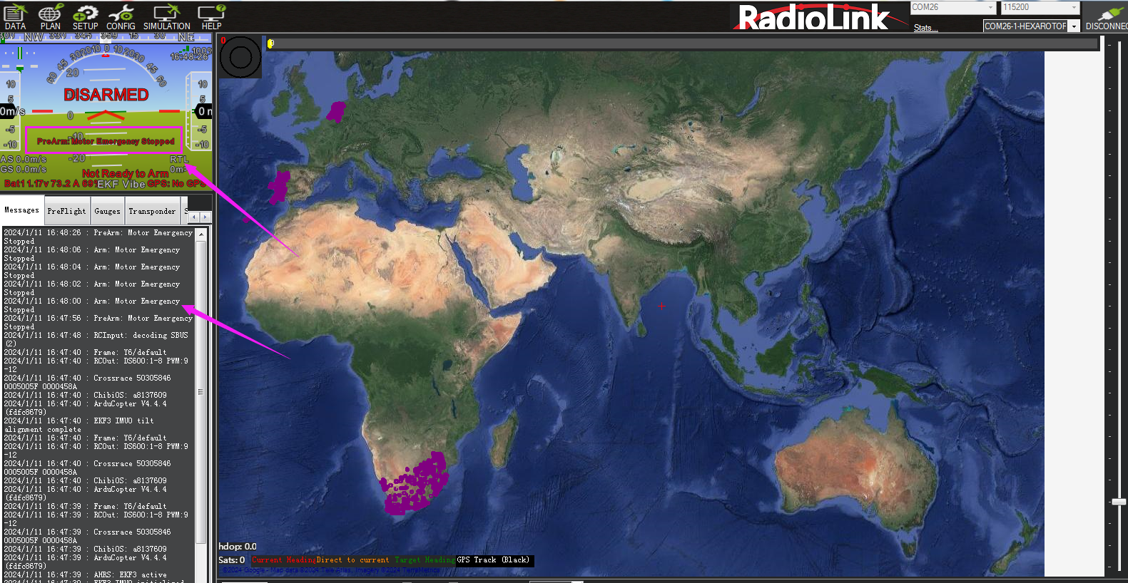
When a prompt starting with PreArm appears in red font, this represents the cause of the fault at this time. For details, you can check the translation and comparison of the prompts below to solve them;
When there is no red font displayed, you can perform the arming action, which will be displayed, or view the top line of text in the message bar;
After solving the fault, power on the flight controller again. After the flight control starts normally, the status indicator light will turn blue and flash, which means it can be armed;
Some failure messages:
safe switch: The safety switch is not closed. Check the value of BRD_SAFETYENABLE in all parameter list. If it is 1, modify it to 0.
RC not calibrated: the radio calibration has not been performed. RC3_MIN and RC3_MAX must have been changed from their default values (1100 and 1900), and for channels 1 to 4, MIN value must be 1300 or less, and MAX value 1700 or more.
Barometer failures:
Baro not healthy: the barometer sensor is reporting that it is unhealthy which is normally a sign of a hardware failure.
Alt disparity: the barometer altitude disagrees with the inertial navigation (i.e. Baro + Accelerometer) altitude estimate by more than 2 meters. This message is normally short-lived and can occur when the flight controller is first plugged in or if it receives a hard jolt (i.e. dropped suddenly). If it does not clear the accelerometers may need to be calibrated or there may be a barometer hardware issue.
Compass failures:
Compass not healthy: the compass sensor is reporting that it is unhealthy which is a sign of a hardware failure.
Compass not calibrated : the compass(es) has not been calibrated. the COMPASS_OFS_X, Y, Z parameters are zero or the number or type of compasses connected has been changed since the last compass calibration was performed.
Compass offsets too high: the primary compass’s offsets length (i.e. sqrt(x^2+y^2+z^2)) are larger than 500. This can be caused by metal objects being placed too close to the compass. If only an internal compass is being used (not recommended), it may simply be the metal in the board that is causing the large offsets and this may not actually be a problem in which case you may wish to disable the compass check.
Check mag field: the sensed magnetic field in the area is 35% higher or lower than the expected value. The expected length is 530 so it’s > 874 or < 185. Magnetic field strength varies around the world but these wide limits mean it’s more likely the compass calibration has not calculated good offsets and should be repeated.
Compasses inconsistent: the internal and external compasses are pointing in different directions (off by >45 degrees). This is normally caused by the external compasses orientation (i.e. COMPASS_ORIENT parameter) being set incorrectly.
GPS related failures:
GPS Glitch : the GPS is glitching and the vehicle is in a flight mode that requires GPS (i.e. Loiter, PosHold, etc) and/or the circular fence is enabled.
Need 3D Fix : the GPS does not have a 3D fix and the vehicle is in a flight mode that requires the GPS and/or the circular fence is enabled.
Bad Velocity: the vehicle’s velocity (according to inertial navigation system) is above 50cm/s. Issues that could lead to this include the vehicle actually moving or being dropped, bad accelerometer calibration, GPS updating at below the expected 5hz.
High GPS HDOP : the GPS’s HDOP value (a measure of the position accuracy) is above 2.0 and the vehicle is in a flight mode that requires GPS and/or the circular fence is enabled. This may be resolved by simply waiting a few minutes, moving to a location with a better view of the sky or checking sources of GPS interference (i.e. FPV equipment) are moved further from the GPS. Alternatively, the check can be relaxed by increasing the GPS_HDOP_GOOD parameter to 2.2 or 2.5. Worst case the pilot may disable the fence and take-off in a mode that does not require the GPS (i.e. Stabilize, AltHold) and switch into Loiter after arming but this is not recommended.
Note: the GPS HDOP can be readily viewed through the Mission Planner’s Quick tab as shown below.
INS checks (i.e. Accelerometer and Gyro checks):
INS not calibrated: some or all of the accelerometer’s offsets are zero. The accelerometers need to be calibrated.
Accels not healthy: one of the accelerometers is reporting it is not healthy which could be a hardware issue. This can also occur immediately after a firmware update before the board has been restarted.
Accels inconsistent: the accelerometers are reporting accelerations which are different by at least 1m/s/s. The accelerometers need to be re-calibrated or there is a hardware issue.
Gyros not healthy: one of the gyroscopes is reporting it is unhealthy which is likely a hardware issue. This can also occur immediately after a firmware update before the board has been restarted.
Gyro cal failed: the gyro calibration failed to capture offsets. This is most often caused by the vehicle being moved during the gyro calibration (when red and blue lights are flashing) in which case unplugging the battery and plugging it in again while being careful not to jostle the vehicle will likely resolve the issue. Sensors hardware failures (i.e. spikes) can also cause this failure.
Gyros inconsistent: two gyroscopes are reporting vehicle rotation rates that differ by more than 20deg/sec. This is likely a hardware failure or caused by a bad gyro calibration.
Board Voltage checks:
Check Board Voltage: the board’s internal voltage is below 4.3 Volts or above 5.8 Volts.
If powered through a USB cable (i.e. while on the bench) this can be caused by the desktop computer being unable to provide sufficient current to the flight controller - try replacing the USB cable.
If powered from a battery this is a serious problem and the power system (i.e. Power Module, battery, etc) should be carefully checked before flying.
Parameter checks:
Ch7&Ch8 Opt cannot be same: Auxiliary Function Switches are set to the same option which is not permitted because it could lead to confusion.
Check FS_THR_VALUE: the radio failsafe pwm value has been set too close to the throttle channels (i.e. ch3) minimum.
Check ANGLE_MAX: the ANGLE_MAX parameter which controls the vehicle’s maximum lean angle has been set below 10 degrees (i.e. 1000) or above 80 degrees (i.e. 8000).
ACRO_BAL_ROLL/PITCH: the ACRO_BAL_ROLL parameter is higher than the Stabilize Roll P and/or ACRO_BAL_PITCH parameter is higher than the Stabilize Pitch P value. This could lead to the pilot being unable to control the lean angle in ACRO mode because the Acro Trainer stabilization would overpower the pilot’s input.
For more failure messages, please refer to the link:
https://ardupilot.org/copter/docs/common-prearm-safety-checks.html
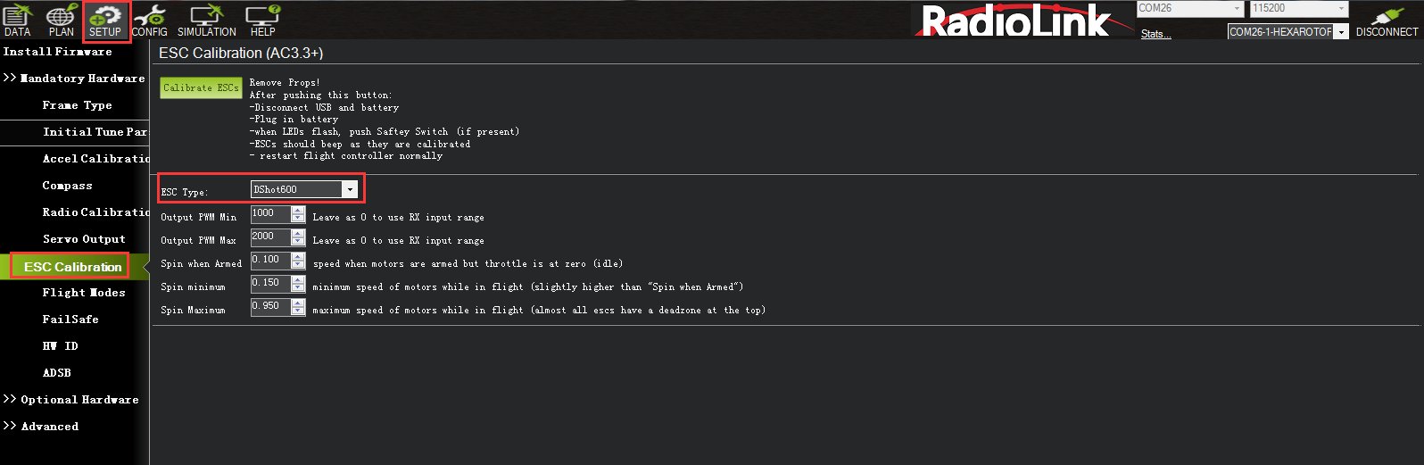
5.4 ESC Calibration
CrossRace is compatible with most ESC protocols, such as Dshot, Oneshot, PWM, etc. You can set different ESC protocols in Mission Planner - Mandatory Hardware - ESC Calibration - ESC Type.
Please first ensure that the aircraft is connected properly, the calibration is completed, and can be armed successfully, and then remove the aircraft propellers.
1. Push the throttle channel of the transmitter to the highest position. Power on the aircraft, and when you see LED flashing in multiple colors, disconnect the power.
2. Power on again. Do not move the transmitter until you hear the beeping sound.
3. Push the throttle channel of the transmitter to the lowest position. After hearing the beeping sound, push the throttle slightly. If the motor rotates, the calibration is done. If not, please try the above steps again.
No: No calibration is needed when using digital ESCs with Dshot Protocol.
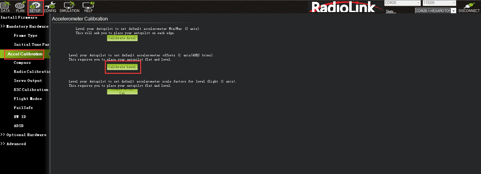
5.5 Level Calibration
If the Mission Planner shows the drone not level when you put it horizontal as this picture, You can setup as below to solve the problem.

Under Initial Setup--Mandatory Hardware--select Accel Calibration from the left-side menu--Click Calibrate Level to start the calibration.
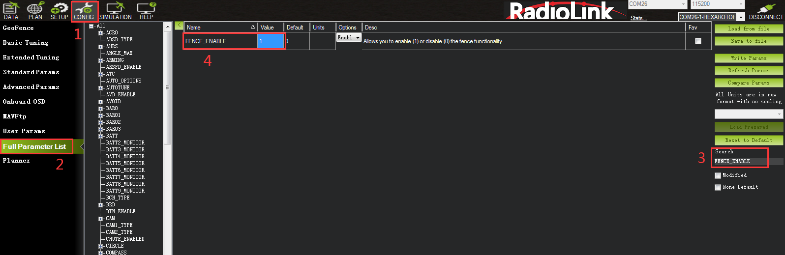
5.6 GeoFence
This is a safety protection mechanism that protects the aircraft from flying out of the range you set. When the function is turned on, it will detect whether the GPS is positioned. If there is no positioning, it cannot be enabled.
The setup steps are as follows:
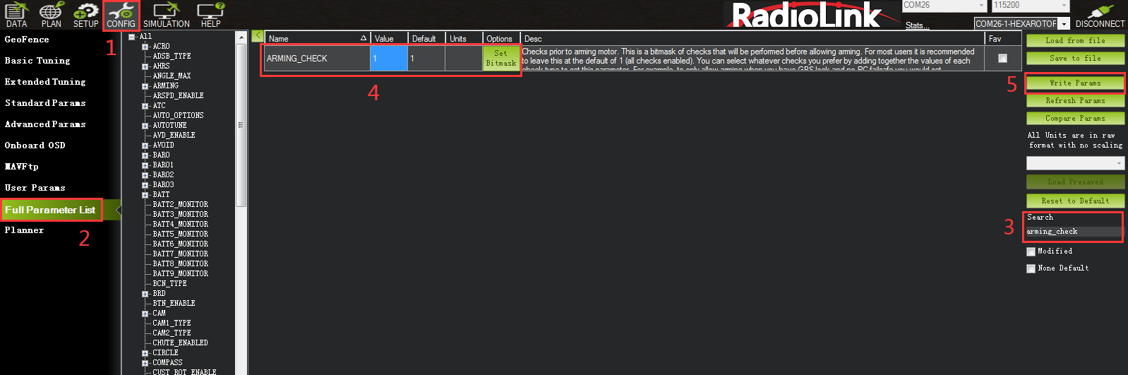
1. Open Full Parameter List.
2. Search for FENCE_ENABLE, change the parameter to 1, and save Params.
Setting parameters introduction:
When setting GeoFence parameters, please search for the following parameters in Full Parameter List and set them.
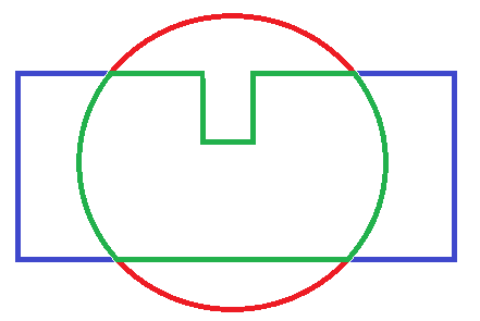
FENCE_TYPE (GeoFence type):
Altitude is the height protection, above which the protection action will be performed.
Circle is circular protection. Take the take-off point as the center of the circle, set the radius to draw a circle, and perform protection actions beyond this range.
Altitude and Circle is cylindrical row protection. The take-off point is the center of the circle, set the radius, height, and the surrounding cylinder, and perform protection actions beyond this range.
Polygon is polygon protection. After drawing the polygon on the map in the flight plan, with the maximum point of 84 points, the protection action will be performed if it exceeds this drawing range.
Altitude and Polygon is height and polygon protection, which adds altitude protection based on polygon protection.
Circle and Polygon is circle and polygon protection, which adds circle protection on the basis of polygon, so that the limited range is the green area, and when the green area is exceeded, the protection is performed.
FENCE_ACTION:
All: The above 3 types of protection are involved.
Report Only: When the restricted area is exceeded, only Mission Planner message prompts and no other operations are performed.
RTL or Land: Return or land.
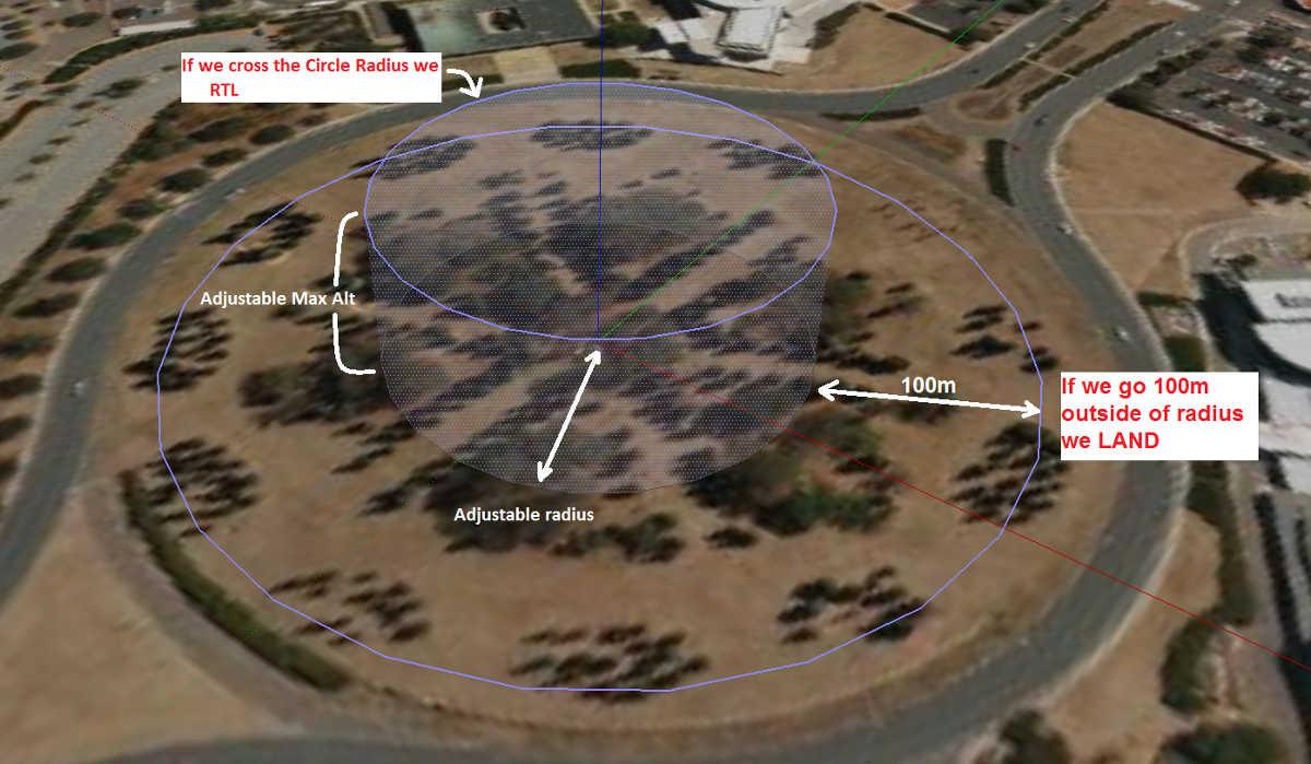
FENCE_ALT_MAX (maximum altitude): protection limit maximum flight altitude (10-1000m)
FENCE_RADIUS (maximum radius): Protection limits maximum flight radius (30-10000m)
FENCE_ALT_MIN (minimum altitude): Protection limit minimum flight altitude (-100-100m)
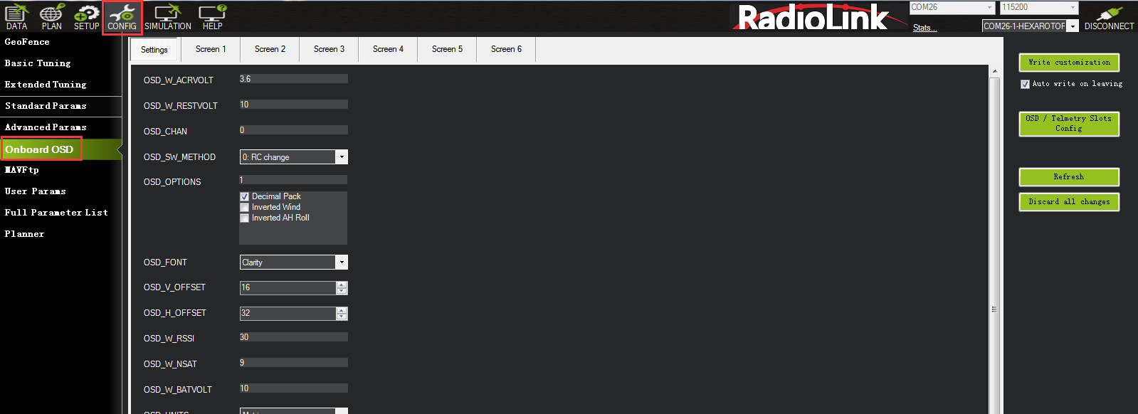
5.7 Onboard OSD
OSD is the abbreviation of On Screen Display in English. It is a kind of screen display technology, which is used to display characters, graphics and images on the display terminal. The status of the aircraft can be displayed in the returned video, and the data of each module can be integrated into the OSD module, and then the OSD module can return the monitored data to the terminal (FPV glasses or screen) and superimpose it on the video transmission image. CrossRace flight controller integrates an OSD chip. Users do not need to connect an external OSD module. They only need to connect the signal lines corresponding to the image transmission and camera to the OSD port of CrossRace to use the OSD function.
5.7.1 Setting Introduction
OSD Parameters
OSD_W_RESTVOLT: RESTVOLT warn level. Set level at which RESTVOLT item will flash Range is from 0 to 100.
OSD_CELL_COUNT: Battery cell count. Used for average cell voltage display. -1 disables, 0 uses cell count autodetection for well charged LIPO/LIION batteries at connection, other values manually select cell count used.
OSD_CHAN: Screen switch transmitter channel. This sets the channel used to switch different OSD screens. The value includes 0, 5-16.
OSD_SW_METHOD: Screen switch method. This sets the method used to switch different OSD screens.
0 = switch to next screen if channel value was changed.
1 = select screen based on pwm ranges specified for each screen.
2 = switch to next screen after low to high transition and every 1s while channel value is high.
OSD_OPTIONS: OSD Options. This sets options that change the display, including Decimal pack, Inverted Wind, Inverted AH Roll.
OSD_FONT: OSD Font. This sets which OSD font to use. It is an integer from 0 to the number of fonts available.
OSD_V_OFFSET: OSD vertical offset. Sets vertical offset of the osd inside image.
OSD_H_OFFSET: OSD horizontal offset. Sets horizontal offset of the osd inside image.
OSD_W_RSSI: RSSI warn level. Set level at which RSSI item will flash. The range is from 0 to 99.
OSD_W_NSAT: NSAT warn level. Set level at which NSAT item will flash. The range is from 0 to 30.
OSD_W_BATVOLT: BAT_VOLT warn level. Set level at which BAT_VOLT item will flash. The range is from 0 to 100V.
OSD_UNITS: Display Units. Sets the units to use in displaying items.
0 = Metric (meters, kilometers, meters/second, kilometers/hour) .
1 = Imperial (feet, miles, feet/second, miles/hour) .
2 = SI (meters, kilometers, meters/second) .
3 = Aviation (feet, nautical miles, feet per minute, knots).
OSD_MSG_TIME: Message display duration in seconds. Sets message duration seconds.
OSD_ARM_SCR: Arm screen. Screen to be shown on Arm event. Zero to disable the feature.
OSD_DSARM_SCR: Disarm screen. Screen to be shown on disarm event. Zero to disable the feature.
OSD_FS_SCR: Failsafe screen. Screen to be shown on failsafe event. Zero to disable the feature.
OSD_BTN_DELAY: Button delay. Debounce time in ms for stick commanded parameter navigation.
OSD_W_AVGCELLV: AVGCELLV warn level. Set level at which AVGCELLV item will flash.
OSD_TYPE: 1 means the chip of OSD is MAX7456.
5.7.2 Screen Introduction
The Screen interface is the interface displayed on the user's screen, where the user can independently design the interface layout, display options, etc.
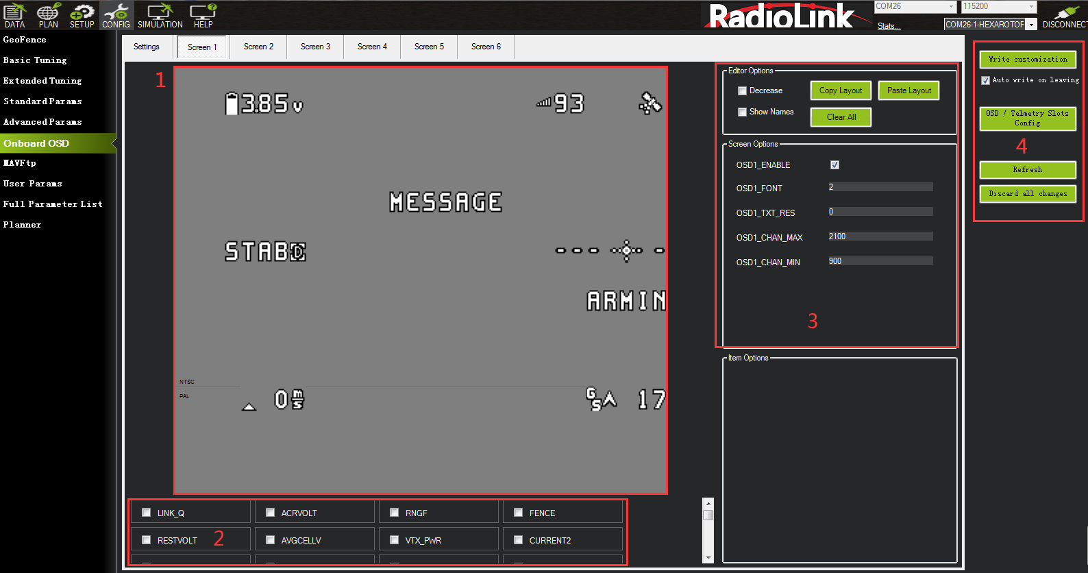
① The area is the layout displayed on the screen. Users can freely drag and drop the options inside to customize and adjust the layout of the screen.
② The area is the content displayed on the screen. Users can tick the content they need and display it on the screen.
③ The area can copy the layout of the current screen or paste the layout of other screens to this screen.
④ Write all the current settings in the area.
5.8 Advanced Functions of CrossRace
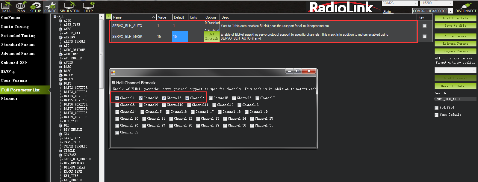
5.8.1 CrossRace Uses ESC Telemetry
Note: The function requires the ESC to support the ESC telemetry function.
Make sure the TELEM of the ESC is connected to the TELEM of the flight controller ESC interface.
Flight controller settings:
1: Search for SERVO_BLH_AUTO in Full Parameter List and change the value to 1.
2: Search for SERVO_BLH_MASK in Full Parameter List and check the channel corresponding to the ESC .(If the ESC is plugged into channel 1 2 3 4, check channel 1 2 3 4.)
3: Search for SERVO_DSHOT_ESC in Full Parameter List and change the value to 1.
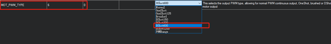
4: Search for MOT_PWM_TYPE in Full Parameter List and modify the value to the corresponding ESC protocol.
5: Restart flight controller.

ESC settings:
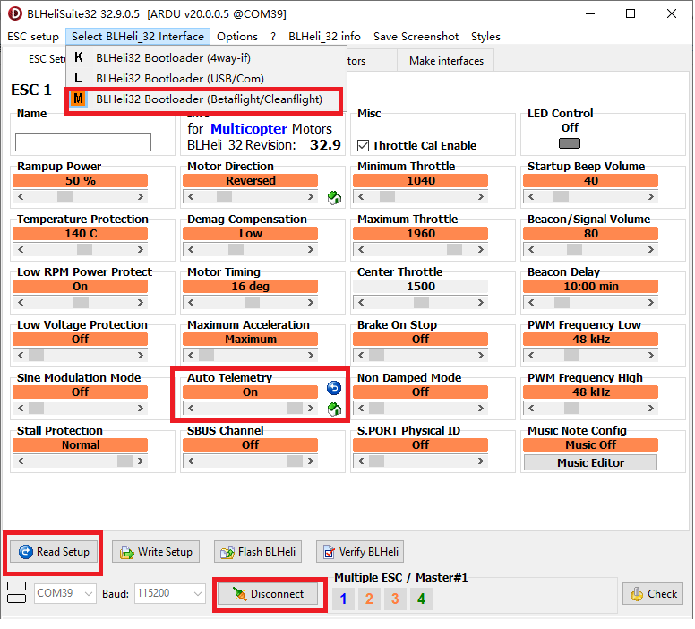
After successfully configuring the flight controller, open BLHeliSuite32.exe. (Please refer to the ESC manual to download the ESC parameter adjustment software.)
1: Select BLHeli32 Bootloader (Betaflight/Cleanflight) in Select BLHeil_32 Interface.
2: Select the corresponding flight controller port and connect.
3: Click Read Setup to read the ESC information.
4: Enable Auto Telemetry of each ESC.
5: Power off and restart. You can see the telemetry information of the ESC in the status bar in Mission Planner.
Note: If you want to set up the ESC, you need to use a separate battery to supply power to the ESC.
5.8.2 CrossRace’s Anti-turtle Mode
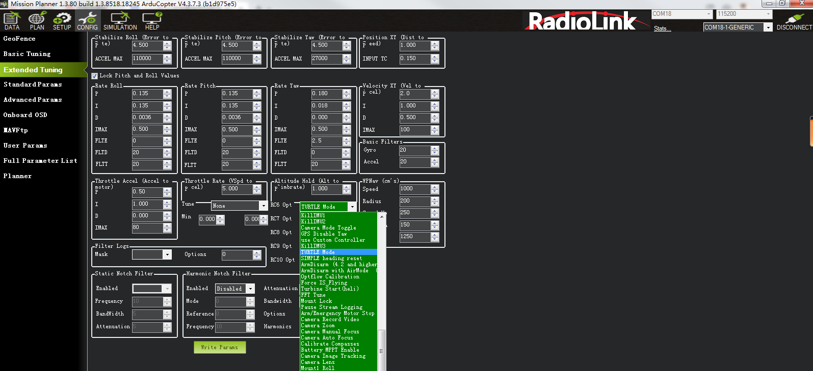
CrossRace's anti-tortoise mode only takes effect when the ESC protocol is Dshot.
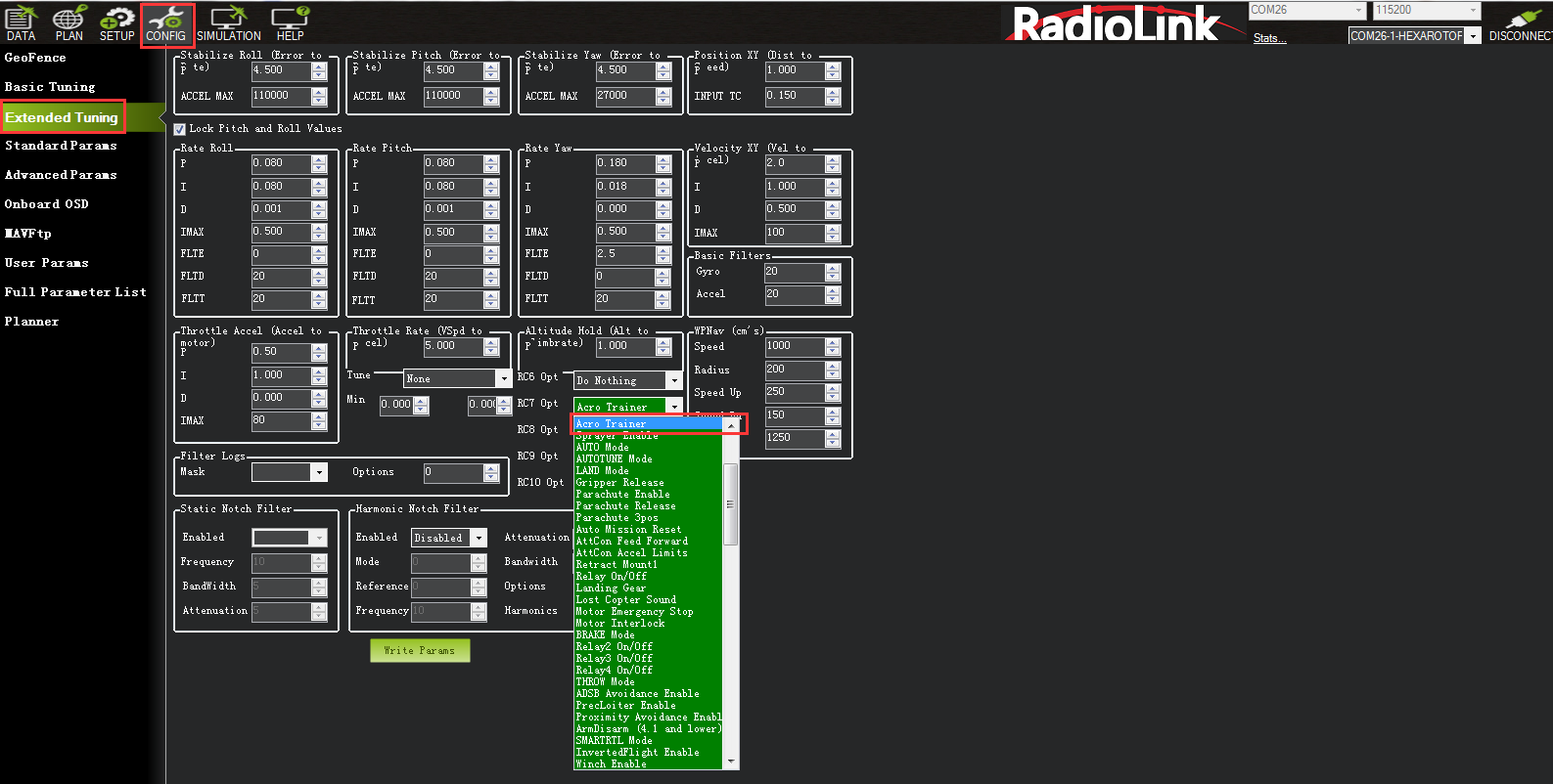
Setting method: Config--Entended tuning--Set Channel opt to Turtle Mode--Write the parameters and restart the flight controller. Anti-turtle mode is enabled when this channel value is high.
6. AutoTune
AutoTune attempts to automatically tune the Stabilize P, Rate P and D, and maximum rotational accelerations to provide the highest response without significant overshoot. Copter needs to be “basically” flyable in AltHold mode before attempting to use AutoTune as the feature needs to be able to “twitch” the copter in the roll and pitch axis.
Position Hold during AutoTune is available in Copter 3.5 (and higher).
Setup before flying
1. Set up one flight mode switch position to be AltHold.
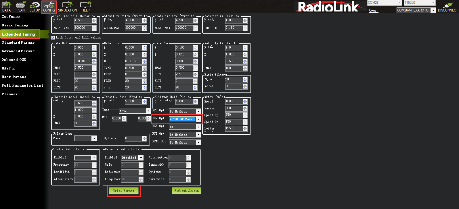
2. Set an Auxiliary Function Switch to Autotune to allow you to turn the auto tuning on/off with the a switch.
3. Remove the camera gimbal or any other parts of the frame that could wobble in flight.
4. Select which combination of axis (roll, pitch, yaw) you wish to tune using the AUTOTUNE_AXES parameter.
5. Set the autotune’s aggressiveness using the AUTOTUNE_AGGR parameter (0.1=agressive, 0.075=medium, 0.050=weak), normally start with the default 0.1.
6. For large copters (with props at least 13inch or 33cm diameter) set the Rate Roll and Pitch filters to 10hz (in Copter-3.3 these are RATE_RLL_FILT_HZ and RATE_PIT_FILT_HZ, in Copter-3.4 they are ATC_RAT_RLL_FILT, ATC_RAT_PIT_FILT).
7. It is recommended to enable battery voltage scaling of PID gains.
How to invoke AutoTune
1. Wait for a calm day and go to a large open area.
2. Ensure the ch7 or ch8 switch is in the LOW position.
3. Take off and put the copter into AltHold mode at a comfortable altitude.
4. Face the vehicle so that it will twitch at 90degrees from the direction the wind is blowing (i.e. if tuning Roll first, point the vehicle into the wind).
5. Set the ch7/ch8 switch to the HIGH position to engage auto tuning:
(1) You will see it twitch about 20 degrees left and right for a few minutes, then it will repeat forward and back.
(2) Use the roll and pitch stick at any time to reposition the copter if it drifts away (it will use the original PID gains during repositioning and between tests). When you release the sticks, it will continue auto tuning where it left off.
(3) Move the ch7/ch8 switch into the LOW position at any time to abandon the autotuning and return to the origin PIDs.
(4) Make sure that you do not have any trim set on your transmitter or the autotune may not get the signal that the sticks are centered.
6. When the tune completes the copter will change back to the original PID gains.
7. Put the ch7/ch8 switch into the LOW position then back to the HIGH position to test the tuned PID gains.
8. Put the ch7/ch8 switch into the LOW position to fly using the original PID gains.
9. If you are happy with the autotuned PID gains, leave the ch7/ch8 switch in the HIGH position, land and disarm to save the PIDs permanently.
If you DO NOT like the new PIDS, switch ch7/ch8 LOW to return to the original PIDs. The gains will not be saved when you disarm.
If you find after performing an AutoTune that the vehicle feels overly twitchy when flying Stabilize, AltHold or PosHold (but ok in more autonomous modes like Loiter, RTL, Auto) try reducing the RC_FEEL parameter to 0.25. This smooths out the pilot’s input. Alternatively try reducing the AUTOTUNE_AGGR parameter (it should always be in the range 0.05 to 0.10) and try again.
If the vehicle feels sloppy after the AutoTune, try increasing the AUTOTUNE_AGGR parameter as high as 0.10 and attempt the autotune again.
7. Parameter Setting
7.1 Parameter Interface Introduction
All of the parameters of CrossRace can setup in Mission Planner, please do not change the parameters during the flight.
Parameters on the left:
GeoFence: Refer to Chapter 5.6 GeoFence.
Basic Tuning: Set Roll/Pitch sensitivity.
Extended Tuning: Adjust PID, 7 and 8 channel function.
Standard Params: Provide some basic settings such as logs, additional functions, channel functions, etc.
Advanced Params: Provide some advanced function settings such as PID.
Onboard OSD: Refer to Chapter 5.7 Onboard OSD.
MAVFtp: In firmware versions 4.1 and above, integrated FTP (File Transfer Protocol) is implemented, allowing access to the SD card (if there is one) and the internal flash file system through this interface. (It is not recommended to use this system to download logs. Please refer to Chapter 8 to download the log, which is faster).
User Params: Quickly set the functions of the auxiliary channel of the transmitter.
All parameter trees: Related function parameters are displayed closely. After a function is expanded, the function-related parameters are displayed.
Planner: Related settings of Mission Planner.
Parameters on the right:
Load from file: load the files with the parameters have setup already.
Save to file: save the file with the parameters to your computer.
Write Params: write the parameters that have modified to CrossRace.
Refresh Params: exhibit the newest parameters which have modified no the Mission Planner.
Compare Params: compare the current and the previous parameters.
Load Presaved: load the parameters that Radiolink upgrade the files which design for 210-250 frame racing drone to CrossRace.
Reset to default: reset all the parameters to default files. Please recalibrate and re-setup all the parameters after reset.
Search: write down the name of parameters you want to setup, much same as the keyboard shortcuts function.
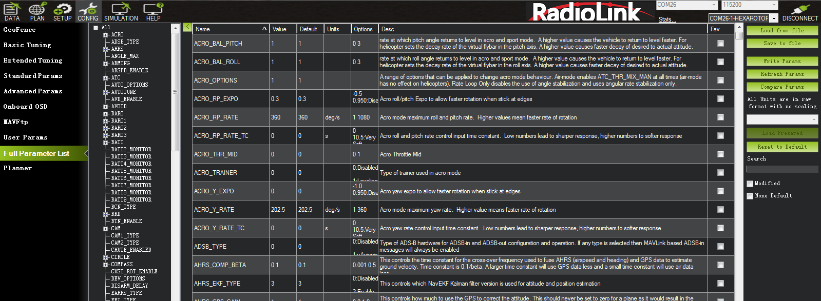
7.2 Parameter Adjustment
All settings of the flight controller can be set or adjusted. You can enter Full Parameter List to search the parameter you want to modify and then modify it. After the modification, please remember to click Write Params on the right.
7.3 Manual Parameter Adjustment
The default parameters of the flight controller may not be applicable for your aircraft and require further manual adjustment. The manual adjustment document is provided below. You can make further fine adjustments according to it. I hope everyone will fly perfectly.
PID Paramater Adjustment Setup Tutorial
7.4 Optimize the Handling of Acro Mode
ACRO MODE is one of the most important flight modes for multi-copters. CrossRace is specifically optimized for ACRO MODE. All parameter optimization in this chapter is based on a suitable PID. Please adjust the aircraft's PID to an appropriate value before performing the following debugging.
Search ACRO_OPTION in Full Parameter List and change the parameter to 1 to turn on air mode (CrossRace has the air mode setting of ACRO_OPTION turned on by default). If there is no air mode, the motor will only remain idle or stop completely when your throttle reaches 0, and the attitude will no longer be controlled at this time. When the air mode is enabled, the flight controller will still keep the PID active even if the throttle stick is in the position of 0. At this time, the aircraft's attitude will still be controlled, and the attitude can be locked during rapid descent or stunts. It is recommended to turn this parameter on.
Search ATC_THR_G_BOOST in Full Parameter List. This parameter is similar to BetaFlight's anti-gravity parameter. It can effectively suppress the problem of the aircraft raising its head when the throttle is pushed hard. If this value is too high, it will cause the aircraft to shake. Please adjust it according to your own aircraft. The adjustment range is 0-1.
Search ACRO_THR_MID in Full Parameter List. This parameter can change the ACRO MODE throttle to a linear throttle. Since the throttle curve of all modes of CrossRace is non-linear by default, this allows the throttle position of the aircraft to take off roughly at the mid-throttle position. In ACRO MODE, this setting may make some pilots unable to adapt and cause problems with throttle control. Pilots can change this parameter to 1 according to their own conditions, and the ACRO MODE throttle will be changed to a linear throttle. The throttle curves of other modes will not be changed by this parameter adjustment. Modifying this parameter may cause some security issues! If you need to change this parameter, please check the description and warning of this parameter in Chapter 3.7.2!
8. Download DataFlash Log
There are two ways to record your flight data. With some exceptions, the two methods record very similar data but in different ways:
Dataflash logs use the CrossRace onboard dataflash memory, which you can download after the flight. On Copter dataflash logs are created after you first arm the copter.
Telemetry logs (also known as “tlogs”) are recorded by the Mission Planner (or other ground station) when you connect ArduPilot to your computer via a telemetry link.
If you are not yet familiar with the basics of these log files, first review the introductory pages to understand where these logs are stored and how you can download and view the information held within them.
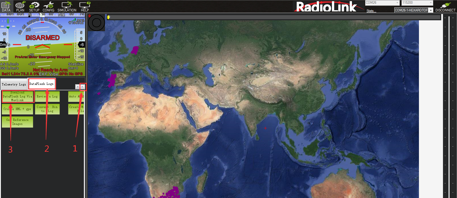
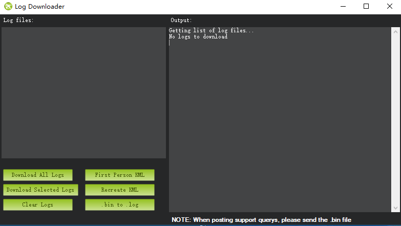
Note: Because the download thread will block the main thread of the flight controller when downloading the log, an internal error will be reported after downloading the log. Please restart the flight controller before the next flight.
Open the log file through the steps below:
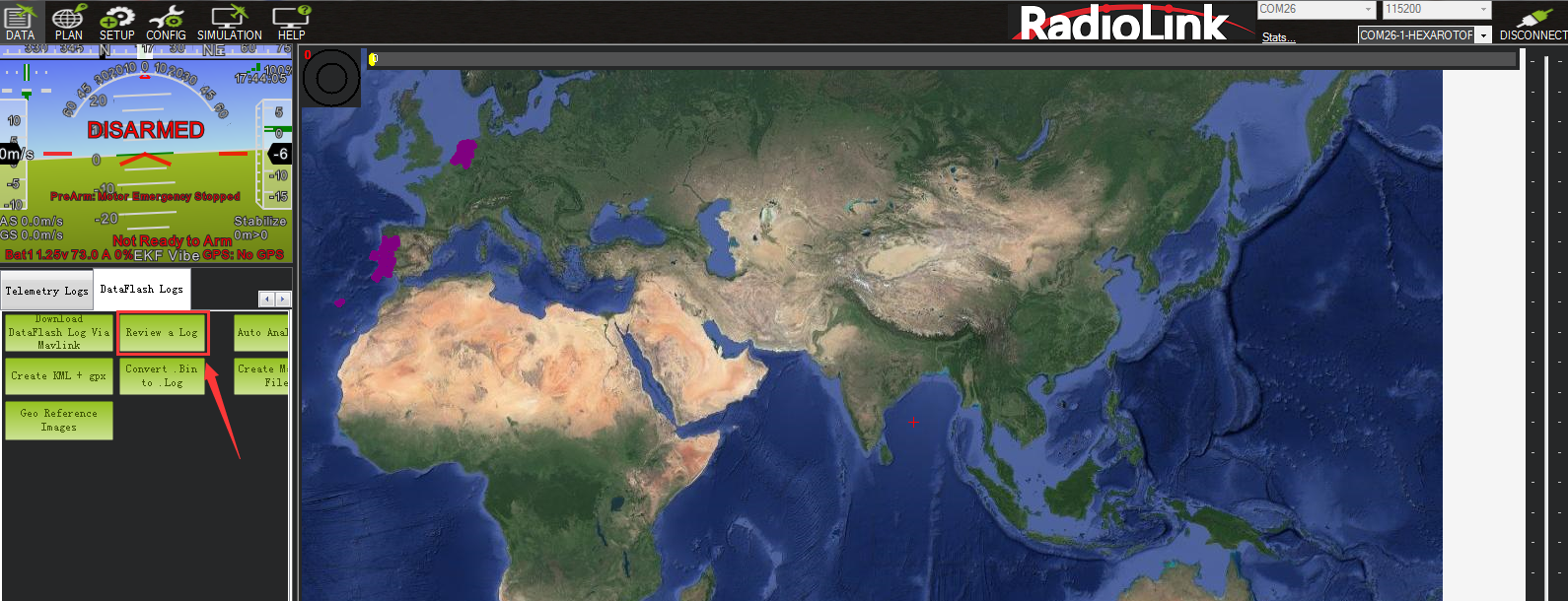
Files available for reference:
http://ardupilot.org/copter/index.html