
1.Specifications
Product Name | RadioLink 70A 4-in-1 ESC |
Model | AM32-70A |
Dimension | 52*48mm(2.05″*1.89″) |
Mounting Pattern | 30*30mm(1.18″*1.18″) |
Weight | 35.3g(1.25oz) |
Type | Brushless, Sensorless |
Input Voltage | 6.0-27.4V(2-6S) |
Output Voltage | Equal to input voltage |
Continuous Current | 70A |
Burst Current | 85A(5 seconds) |
Current Sensor Output | 7.5mV/A |
ESC Firmware | AM32_AT32DEV_F421_2.19 |
Motor Timing | 15° |
Protocols | PWM, Dshot300, Dshot600 |
MCU | AM32 AT421 |
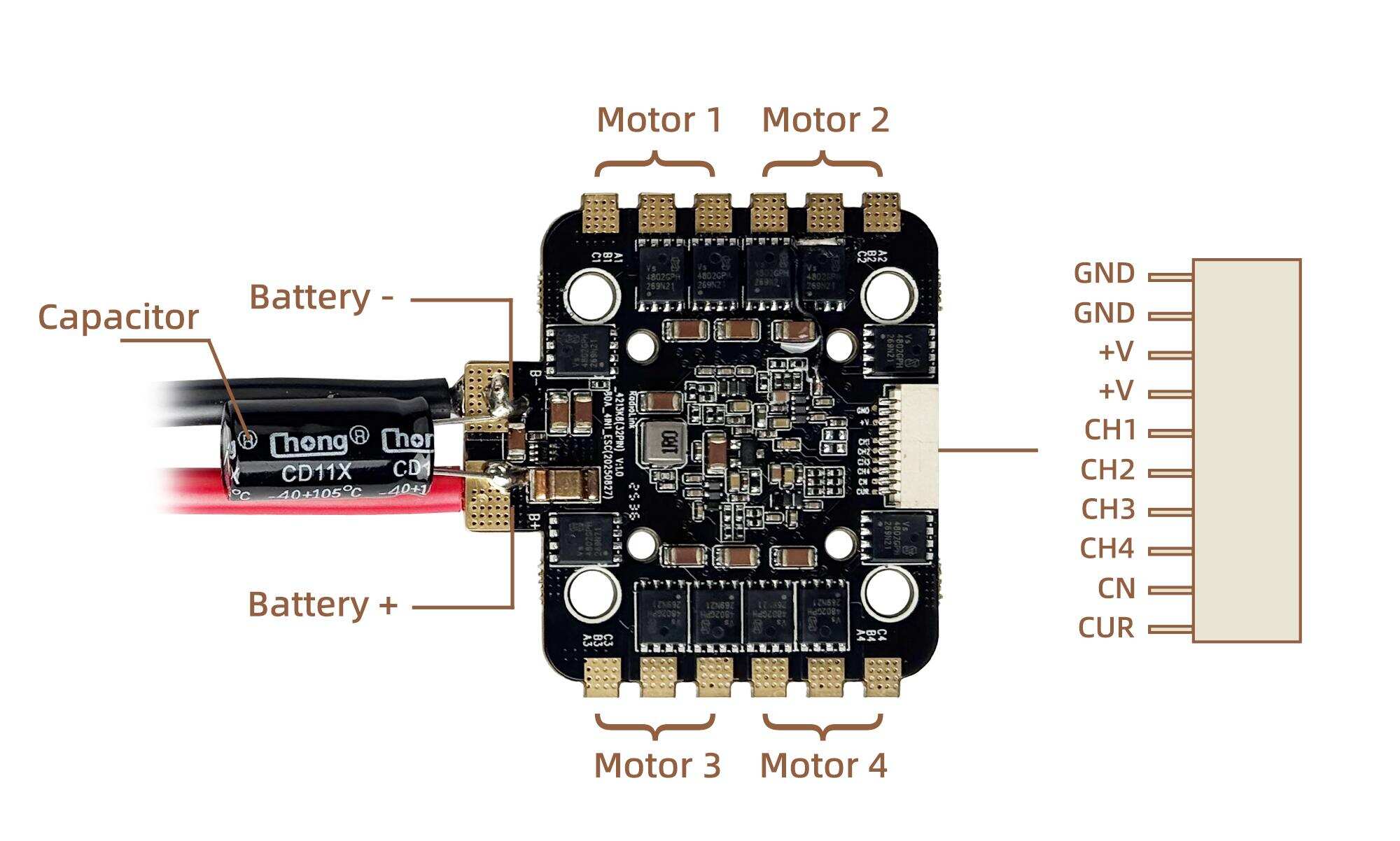
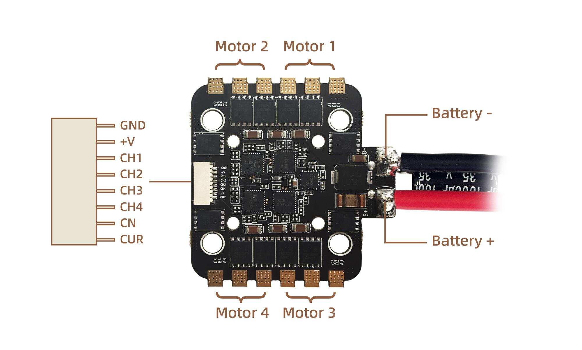
2.Interface definition
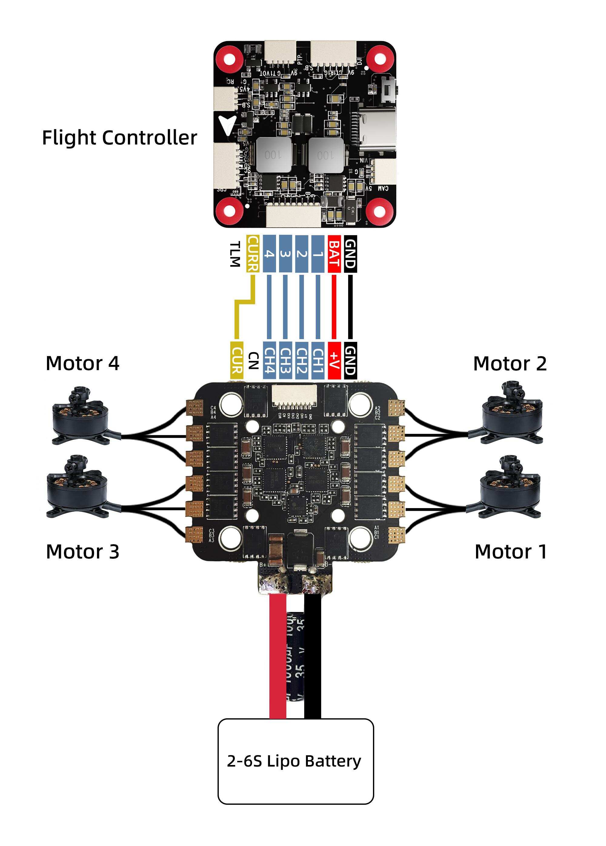
3.Connection diagram
 4.ESC configuration
(1) Flash the firmware of the flight controller.
During the configuration of ESC parameters, a flight controller running Betaflight, INAV, or ArduPilot firmware is required as a communication bridge between the ESC and the computer. First, confirm whether the current flight controller is running Betaflight, INAV, or ArduPilot firmware. If not, please flash the firmware to the flight controller. For specific flashing instructions, please refer to the manual of the flight controller.
(2) Configure the flight controller.
The Betaflight firmware or ArduPilot firmware requires no configuration. The INAV firmware requires enabling motor output, which is disabled by default.
(3) Connect the flight controller and ESC
After soldering the motors to the ESC, connect the ESC to the flight controller. Then connect the battery (2-6S battery) to the ESC, and finally connect the flight controller to the computer by using a USB cable.
Configure ESC.
It is recommended to configure the parameters of the ESC by the following methods :
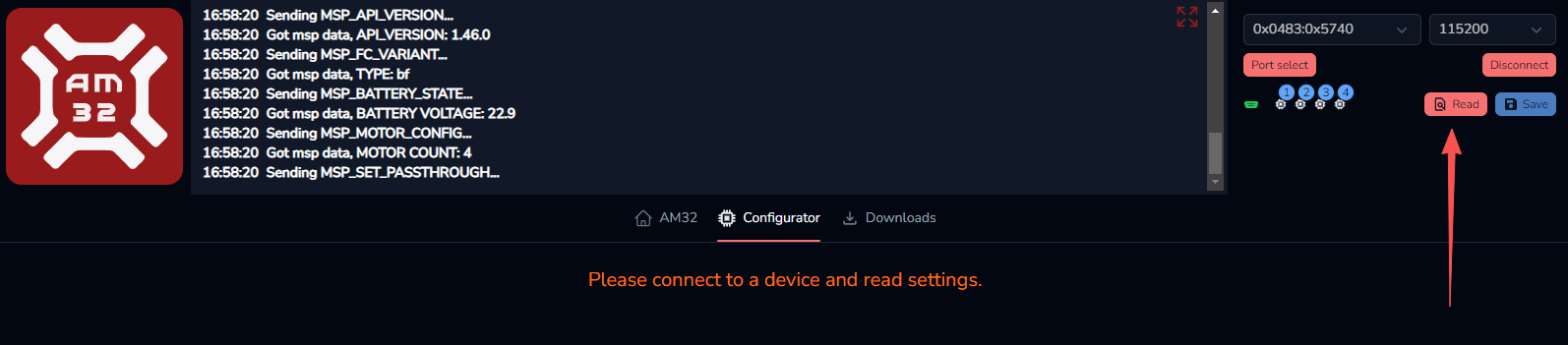
Open https://am32.ca/configurator (Note that it only supports Chromium-based browsers such as Chrome, Edge etc.). Click "Port select" in the upper right corner. Select the correct flight controller port to connect to, and then click the "Connect" button to start connecting to the ESC.
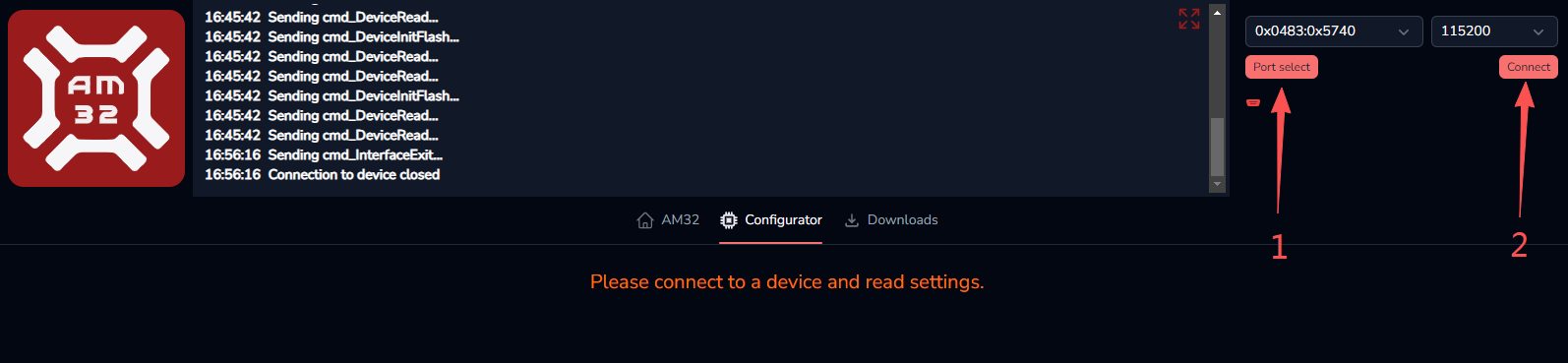
After they are connected, click "Read" button to read the ESC data.
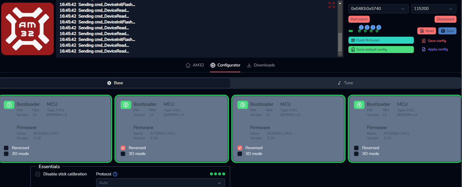
After the ESC data is successfully read, the interface shown below will appear. Users can modify the ESC parameters as needed. After modifying the parameters, please click "Save" in the upper right corner to save the parameters. Otherwise, the modified parameters will not take effect.
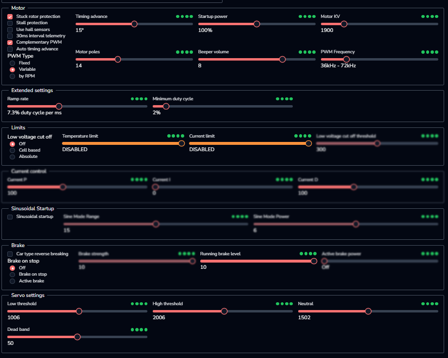
Here is the introduction of the functions:
Option | Introduction |
Stuck rotor protection | A safety mechanism is in place to prevent damage to the ESC or motor from continuous high current when the motor is stalled |
Stall protection | Function to prevent motor from stalling due to insufficient torque under low speed or high load conditions |
Use hall sensors | When using a sensor-activated brushless motor, it can be kept off unless there are special requirements |
30ms interval telemetry | Keep it off unless there are special requirements |
Complementary PWM | Dual-speed control can be achieved by keeping it on unless there are special requirements. It can improve motor efficiency, reduce motor noise and electromagnetic interference, and enable forward and reverse rotation of the motor |
Auto timing advance | Dynamically adjusts the motor advance angle, suitable for racing/flower flying |
Variable PWM | The ESC dynamically adjusts the PWM drive frequency based on the motor speed or other operating conditions, rather than using a fixed frequency |
Timing advance | In most cases, the default value of 15 is sufficient. Adjustments may be considered for special motors |
Startup power | The default settings are generally fine. You can consider increasing them when the load is heavy |
Motor KV | It should be set to an approximation value that is closest to the actual value, and together with the number of poles, it determines the threshold for low-speed power failure protection and high-speed stall protection |
Motor poles | The number of pairs of magnetic poles inside a brushless motor, that is, the number of pairs of N and S poles appearing on the motor rotor |
Beep volume | Motor beep volume |
PWM frequency | The internal MOSFETs of the ESC, which performs pulse width modulation (PWM), is the number of times they switch per second, measured in Hertz (Hz) . This frequency is not adjustable when using the variable frequency PWM function |
Ramp rate | The maximum permissible speed of change in throttle input |
Minimum duty cycle | The minimum effective drive power that the ESC outputs to the motor, which is equivalent to the engine's "idle speed" |
Low voltage cut off | A protective mechanism to prevent battery damage from over-discharge |
Temperature limit | The maximum operating temperature threshold set internally by the ESC. It is used to trigger the overheat protection mechanism to prevent hardware damage due to excessive temperature |
Current limit | The maximum output current value that the ESC allows the motor to pass through (since most ESCs do not have a current sensor, so it can be left disabled by default) |
Running brake level | The force used to brake the motor while it is still rotating |
Low threshold | Throttle lower limit |
High threshold | Throttle limit |
Neutral | Throttle in the middle |
Dead band | A range in the throttle signal that will not trigger a motor response ; that is, when the throttle lever is moved within this range, the ESC will not output any power |
5.Firmware upgrade
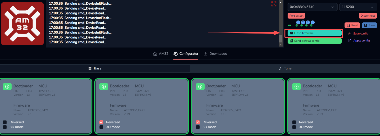
(1)After the ESC data is successfully read on the website https://am32.ca/configurator webpage, click "Flash Firmware" button in the upper right corner, and a box for upgrading the ESC firmware will pop up.
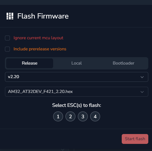
(2)Select the firmware version you want to upgrade from the drop-down menu. It is best to select the latest version.
(3)The numbers below indicate which ESC will be upgraded. Generally, all four are selected simultaneously.
(4)Finally, click "Start flash" to begin firmware flashing. Firmware flashing may take approximately several tens of seconds. Please be patient. Note: Do not disconnect the power during the firmware flashing process. Otherwise, the ESC will be bricked. If bricked, the firmware can only be upgraded by using a programmer.
6.Attention
All soldering tasks require good soldering technique. Short circuit between components or wires should be avoided at any time.
Please ensure all solder joints are insulted with hear shrink where necessary.
Please double check the polarity is correct before power up.
Never disassemble any electronic components in the ESC by yourself, or permanent damages or lost ofinformation will occur.
Do not install propeller on the plane when test the ESC and motor.
Do not use cracked or broken battery pack.
Do not use battery pack easily get overheat.
Do not use cable insulation material against standards.
Do not use cable connector against standards.
The voltage of battery shall not exceed the scope of working voltage of ESC.
Do not place the ESC in moist or over exposure.
Do not unplug the battery when the motor is working, for the generated large peak current will damage the ESC.
Do not pack anything outside the ESC. Install the ESC in places with good ventilation and heat dissipation as far as possible.
Technical Support Here


Contact RadioLink RL AM32-70A User Manual AM32-70A FAQ AM32-70A Tutorials
via Facebook Messenger
If the above communication cannot solve your problem, you can also send emails to our technical support: after_service@radiolink.com.cnThis content is subject to change. Please download the latest version from https://radiolink.com.cn/am32_70a_4in1_esc_user_manual
Thank you again for choosing the RadioLink product.