How do we connect and set parameters when the CrossFlight/CrossFlight-CE works with the SUI04?
The SUI04 module can realize Alt-hold, obstacle avoidance in four directions (front, rear, left, and right), and upward collision avoidance. Here is how to set CrossFlight/CrossFlight-CE to work with SUI04.
Chapter 1. Connect SUI04 to CrossFlight/CrossFlight-CE
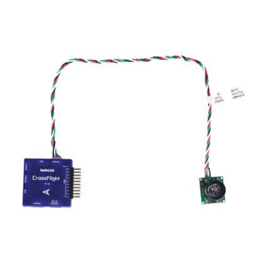
1.1 Connect SUI 04 to CrossFlight/CrossFlight-CE GPS port directly
SUI04 has a cable connecting the CrossFlight/CrossFlight-CE/Mini Pix flight controller(4 Pin to 6 Pin). The 4 Pin end is connected to SUI04, and the 6 Pin end is connected to the GPS port of CrossFlight/CrossFlight-CE, as shown below:
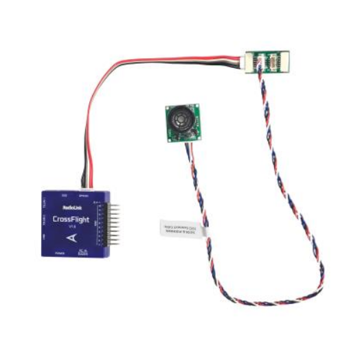
1.2 Connect SUI04 to CrossFlight by I2C transfer board
CrossFlight/CrossFlight-CE has an I2C transfer board and connect cable(6 Pin to 6 Pin). Connect one end to the GPS port of CrossFlight/CrossFlight-CE, and the other end to the I2C transfer board. Then use the 12C/PIXHAWK connect cable that comes with SUI04 (4 Pin to 4 Pin) to connect one end to the I2C transfer board, and the other end to SUI04, as shown below:
Note: The I2C port of CrossFlight/CrossFlight-CE cannot be connected to more than 6 devices at the same time, otherwise data loss may occur.
Chapter 2. Alt-Hold Function
2.1 Button Functions of SUI04
For Alt-hold function, the direction of SUI04 downward can be set up by pressing the same button. Each time you press the button, the module direction changes once. After pressing once, you need to wait for the module light to flash. When finished, press it a second time until the light of SUI04 flashes 5 times, which means the current direction of the module is downward.
2.2 Parameter Setup
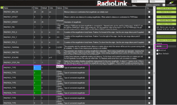
(1) Connect the flight controller to Mission Planner. Enter CONFIG--Full Parameter List. Search RNGFND1_ and change the value of RNGFND1_TYPE to 2. Click Write Params. Then power off the flight controller and restart it.
(2) After reconnecting to Mission Planner, SUI04 can be recognized. As shown below:
Change the value of RNGFND1_MAX_CM to 450, RNGFND1_MIN_CM to 43 (cm), and RNGFND1_ORIENT to 25. As shown below:
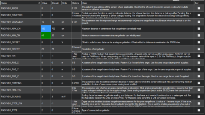
RNGFND1_MAX_CM is the maximum distance in centimeters that rangefinder can reliably read.
RNGFND1_MIN_CM is the minimum distance in centimeters that rangefinder can reliably read.When the distance sent by SUI04 exceeds 43~450cm, the flight control will not recognize the distance of SUI04, so it will achieve the alt-hold by the barometer.
2.3 Data View
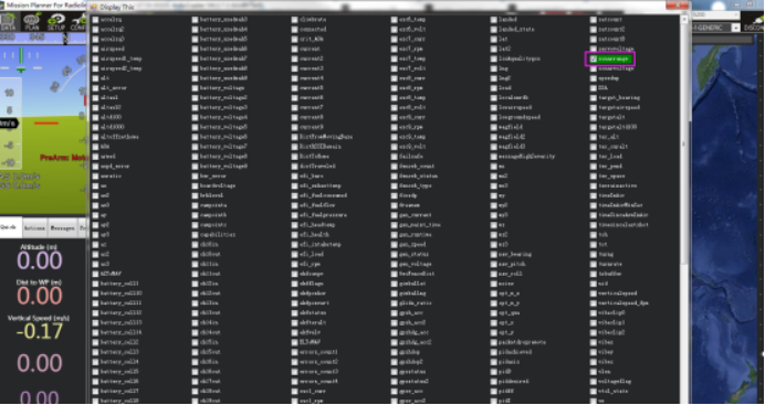
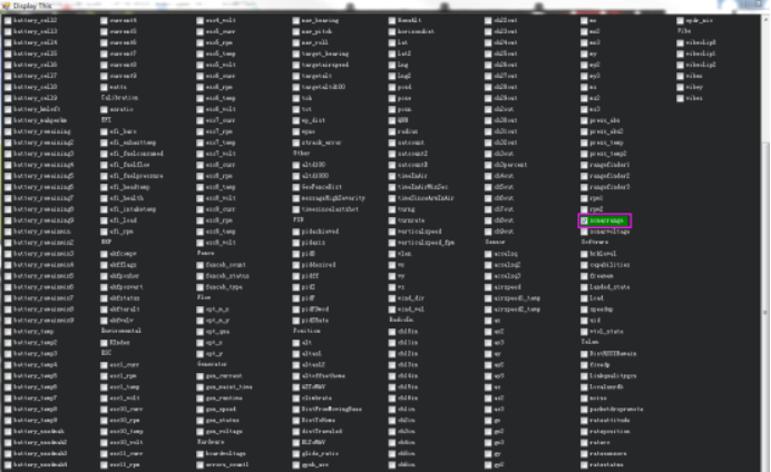
(1) View ultrasonic data in the quick interface.
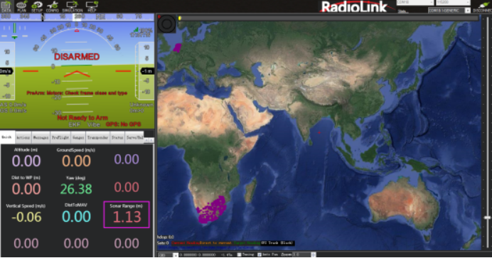
Connect the flight controller to Mission Planner. Double-click in the quick interface, and a large list will appear. Select sonarrange in the list, and the ultrasonic height data will be displayed.
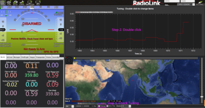
(2) View ultrasonic data in the Tuning interface.
Check the Tuning option in Mission Planner. Double-click the dynamic table, and select sonarrange in the list to display the dynamic waveform of ultrasonic data. As shown below:
Chapter 3. Obstacle Avoidance
3.1 Button Setup
The SUI04 module can realize obstacle avoidance in four directions (front, rear, left, and right). The directions can be changed by pressing the button on SUI04. The default direction of the module is forward. Each time the button is pressed, the direction of the module changes clockwise, and the module LED flashes. Different flash frequencies mean different directions: Once-Front, Twice-Right, 3 Times-Back, 4 Times-Left. After the direction is set, the module needs to be powered off and restarted.
3.2 Parameter Setup
(1) Connect SUI04 to the flight controller. Search PRX1_TYPE in Full Parameter List and change the value to 4. Then search RNGFND in Full Parameter List and change the value of RNGFNDx_TYPE to 2 (x represents the ultrasonic serial number). Finally, restart the flight controller. As shown below:

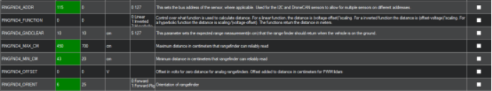
(2) Search RNGFND1 in Full Parameter List. Modify RNGFND1_ADDR to 116, RNGFND1_MAX_CM to 450, RNGFND1_MIN_CM to 43, and RNGFND1_ORIENT to 0. (0 indicates that the ultrasonic direction is forward.). As shown below:
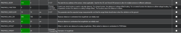
(3) Search RNGFND2 in Full Parameter List. Modify RNGFND2_ADDR to 113, RNGFND2_MAX_CM to 450, RNGFND2_MIN_CM to 43, and RNGFND2_ORIENT to 2 (2 indicates that the ultrasonic direction is to the right.). As shown below:
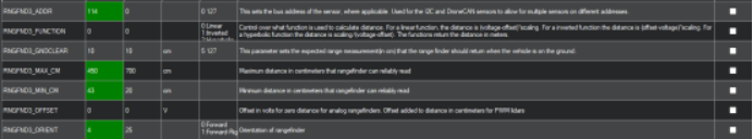
(4) Search RNGFND3 in Full Parameter List. Modify RNGFND3_ADDR to 114, RNGFND3_MAX_CM to 450, RNGFND3_MIN_CM to 43, and RNGFND3_ORIENT to 4 (4 indicates that the ultrasonic direction is backward.). As shown below:
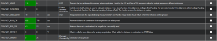
(5) Search RNGFND4 in Full Parameter List. Modify RNGFND4_ADDR to 115, RNGFND4_MAX_CM to 450, RNGFND4_MIN_CM to 43, and RNGFND4_ORIENT to 6 (6 indicates that the ultrasonic direction is to the left.). As shown below:
(6) Click Write Params. Then power off the flight controller and restart it. After reconnecting to Mission Planner, SUI04 can be recognized.
3.3 Set the Avoidance Distance and Avoidance Enable/Disable
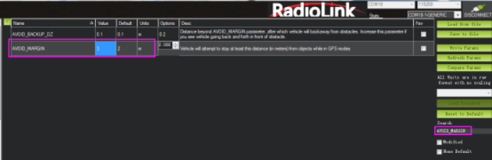
(1) The obstacle avoidance distance of SUI04 can be set by changing the value of AVOID_MARGIN.
AVOID_MARGIN: The vehicle will attempt to stay at least this distance (in meters) from objects while in GPS mode.
(2) Parameter Settings
Search AVOID_MARGIN in Full Parameter List, and modify it to 3 (That is, 3 meters. The valid value is 1~10). Then click Write Params.
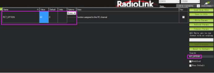
(3) Set RC7_OPTION
Search RC7_OPTION in Full Parameter List, and modify it to 40. Then click Write Params. As shown below:
(4) Transmitter Setup
This setup is optional.
The avoidance function of the flight controller is always automatically enabled in Loiter Mode by default and disabled in Stabilize Mode. If users prefer enabling/disabling the avoidance function by transmitter, set up the transmitter by following the steps below :
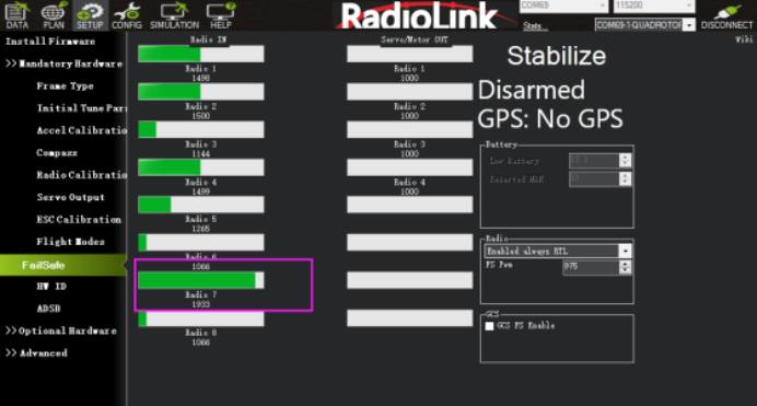
1) Choose a 2-position switch to control CH7.
2) Connect Mission Planner. Enter SETUP-- Mandatory Hardware--FailSafe. The PWM value of CH7 is shown.
3) Toggle the switch of CH7. If the PWM value of CH7 is more than 1800, it means the avoidance function is enabled when the switch is at that position. If the PWM value of CH7 is less than 1800, it means the avoidance function is disabled when the switch is at this position.
3.4 Data Display
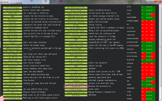
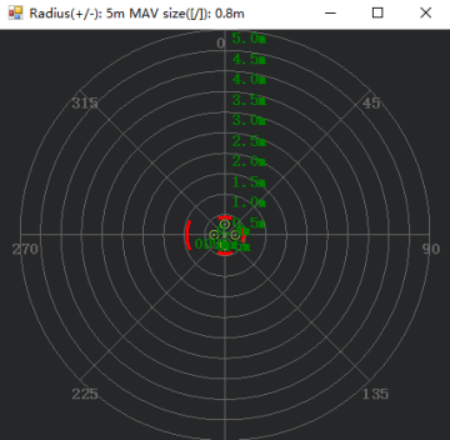
Connect the flight controller to Mission Planner. Press CTRL+F on the keyboard, and click Proximity in the pop-up window. As shown below:
Ultrasound data can be displayed in a pop-up window, as shown below:
Chapter 4. Collision Avoidance Upward
4.1 Button Setup
The collision avoidance upward function is the same as the obstacle avoidance function; the direction of SUI04 upward can be set up by pressing the same button. Press the button 6 times and the LED flashes 6 times, and the direction of SUI04 is set upward. The corresponding collision avoidance distance can be set by the value of AVOID_MARGIN as the previous steps instructed.
4.2 Parameter Setup
(1) Connect SUI04 to the flight controller. Search PRX1_TYPE in Full Parameter List and change the value to 4. Then search RNGFND in Full Parameter List and change the value of RNGFNDx_TYPE to 2 (x represents the ultrasonic serial number). Finally, restart the flight controller. As shown below:
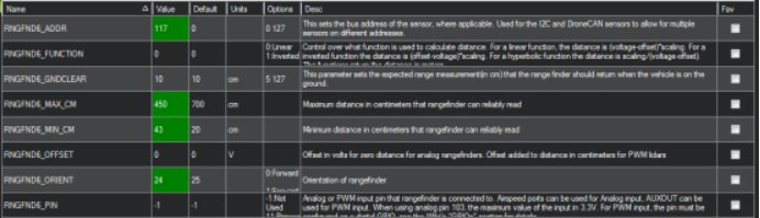
(2) Search RNGFND in Full Parameter List. Modify RNGFNDx_ADDR (x represents the ultrasonic serial number) to 117, RNGFNDx_MAX_CM to 450, RNGFNDx_MIN_CM to 43, and RNGFNDx_ORIENT to 24. (24 indicates that the ultrasonic direction is forward.). As shown below:
4.3 Data Display
As only the horizontal distances are available on the data check interface, upward data can only be checked on DataFlash Logs. The steps are as follows:
(1) DataFlash Logs Download
Connect the flight controller to Mission Planner and follow the below steps to download DataFlash Logs.
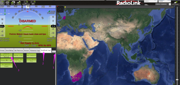
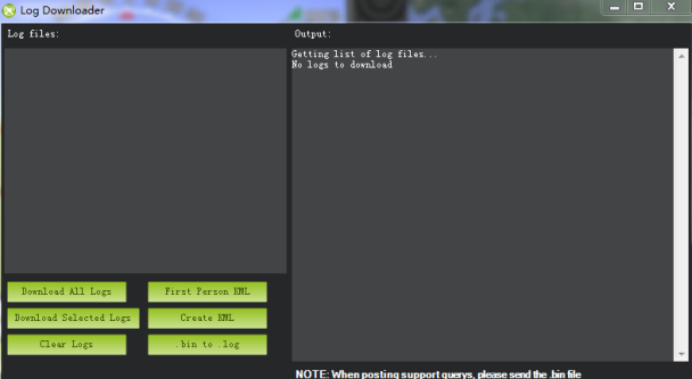
Click the logs you want to view, and click Download these logs to download the selected logs.
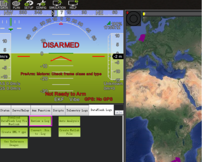
(2) Log Check
Click Review a Log and open the log.
Follow steps 1 and 2 in the picture below.
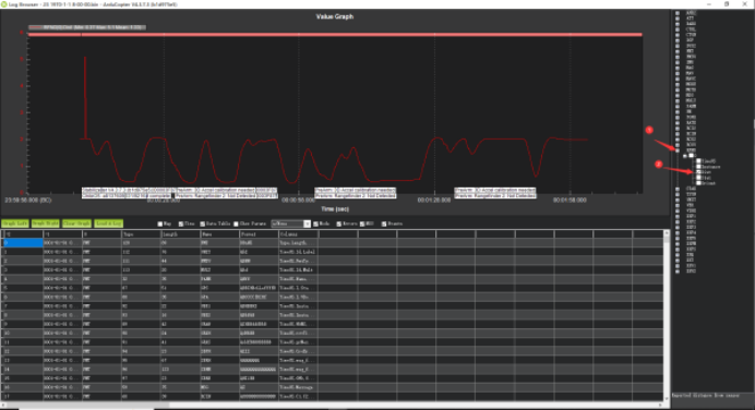
The data shown in the chart is the distance of objects detected by SUI04.