Analysis of Response Speed of Transmitters
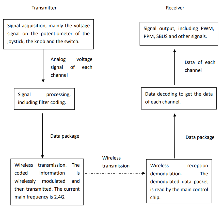
1. Signal Transduction Pathway

2. Factors Influencing the Latency.
The remote-control response speed mainly depends on the latency of the transmitter and other control devices such as servos. Among them, the latency of the transmitter is the main factor. The latency of the transmitter depends on many factors, including joysticks, receiver output, etc., as listed below.
1) Transmitter
① Signal acquisition.
When the joysticks rotate, the potentiometer in it rotates the shaft, and the voltage on the center tap of the potentiometer changes synchronously to obtain a continuously changing analog signal. This voltage signal is input to the ADC pin of the chip (abbreviated as an analog-digital convert). The current ADC mainly is 12bit (bit), which has a resolution of 212=4096. The response speed will usually not be affected as long as the signal acquisition is done before transmission. And the response speed generally won’t be affected.
② Signal processing.
Signal processing is to pack the data of each channel into an array, and the length of most data packets is within 64 bytes. As long as it is packaged before wireless transmission, it will not affect the response speed.
③ Wireless transmission.
Signal acquisition and processing are handled by the main control chip. Currently, the main control chip is more than enough to handle data of less than 64 bytes. Unless the main control chip is dragged down by other program overhead, such as an operating system that exceeds the chip's resources. Therefore, the main influence of the transmitter is wireless transmission. The most important thing for wireless transmission is the transmission rate, which is similar to the WiFi transmission rate. The higher the rate, the faster the response speed. Wireless transmission is the factor that most affects the response speed in the transmitter among the three factors. The current wireless rate of the chip is generally above 40kbps (kilobits per second), and the transmission of 64 bytes is completed within 10ms. You will not feel much difference during use.
2)Receiver
① Wireless reception.
There is a lot of interference in wireless reception. 2.4G belongs to the open frequency band, with WiFi, Bluetooth, etc. all in this frequency band. Once it is interfered with by the same frequency, it will lead to the loss of the data packet, commonly known as packet loss, and packet loss has the greatest impact on the response speed. For example, there is no problem when you use it alone, but there is a problem when it comes to the field with many devices operating at the same time. Therefore, anti-interference is the most effective way to improve response speed. Anti-interference mainly depends on the communication algorithm and the anti-interference ability of the chip itself. It is also related to the transmission rate set. The lower the transmission rate, the farther the transmission distance and the more anti-interference. Therefore, appropriately reducing the transmission rate without affecting the operating experience is also an option to improve the response speed in actual use. Special equipment can measure the reduction of the transmission rate at a speed without interference or close to the joystick. And generally, it will not affect the operating experience.
② Decoding.
Decoding is to restore the packaged data into each channel. As long as the 2.4G chip receives the packet and reads and processes it in time, the response speed will generally not be affected.
③ Output.
The current signal output is parallel PWM (pulse width modulation), serial PPM (pulse position modulation), SBUS, etc. The latency of the signal output mainly includes the output update and output cycle after decoding. It is not difficult to output and update the current main control chip resources, as long as the program is written well. In the output cycle, PPM is composed of a series of pulses, and its cycle cannot be compressed. SBUS has cycles of 14ms, 7ms, and 4ms. A short cycle can be selected to improve the response speed. PWM output is aimed at servos and ESC, including conventional analog servo 20ms (50 Hz frequency) cycle (analog servo cycle) signal format and digital servo short cycle 4ms (250 Hz) and 3ms (333 Hz) signal format. The digital servo can significantly improve the response speed, especially for the occasion of quick adjustment of the gyroscope and flight controller. The flight controller or gyroscope with a digital servo generally outputs a short cycle. If the transmitter directly controls the servo, as long as the overall latency is within 20ms, the operating experience will not be greatly affected.
3. Summary.
To sum up, the factors affecting the latency of the transmitter are wireless reception, receiver output, wireless transmission rate, decoding, encoding, and signal acquisition. The wireless latency caused by wireless reception is uncertain due to the influence of the environment, and the latency caused by other factors is the ideal latency without interference, and the ideal latency is definite.
Movies have 24 frames per second. If the transmitter is designed to reach 50 frames per second which means it can transmit more than 50 data packets per second, there will be no latency felt basic. The amount of data in the transmitter is very small compared to audio and video, so with the current chip technology, the response speed is relatively satisfactory under the condition of no interference and ideal latency. That is to say, the response speed is no longer a pain point. The main challenge is the wireless latency caused by continuous packet loss when interference occurs. User experience is the most accurate test of response speed, which includes ideal latency without interference and wireless latency with interference. The test data of the ideal latency close to the interference-free condition can be used as a reference, but it does not represent the whole latency.
In the actual test, when controlling the cars, the response speed can be tested through curves; when controlling the aircraft, the response speed can be tested through turns and attitude changes. The actual use test is comprehensive. It is best to test the response speed of a car in a field of more than 100 meters and under the condition of multiple people competing in the same field.
Excessive pursuit of certain data often has a negative effect on the user experience. For example, for the wireless transmission rate, 200kbps and 1Mkbps can both transmit dozens of bytes within 2ms. Although the difference can be tested by devices, it has nothing different for user experience. But faster transmission rates are less effective against interference at long distances. RadioLink AT9/AT9S uses a 250Kbps CC2533 chip, with a TI 1Mbps baud rate. The wireless transmission rate of a data packet is within 2ms, with an output cycle of 3ms. When upgrading it to AT9S Pro, in addition to increasing the frequency hopping communication, the transmission cycle is also appropriately increased to reduce the collision rate in the air, so that the response speed is faster, which shows the decisive role of wireless latency.