The Operation Guide on How to Add an Anti-interference Capacitor on CB86-PLUS
When using CB86-PLUS, you can try to add anti-interference capacitors to solve the problem in the following two cases:
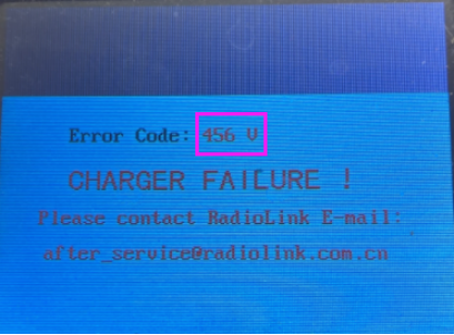
1. The firmware of CB86-PLUS has been upgraded to the latest firmware, and there is an error code on the screen: number + V (such as 2V, 145V, 456V, see picture below). The error code number + V still exists after powering it on. You can add anti-interference capacitors on CB86-PLUS to solve it by following the below steps.

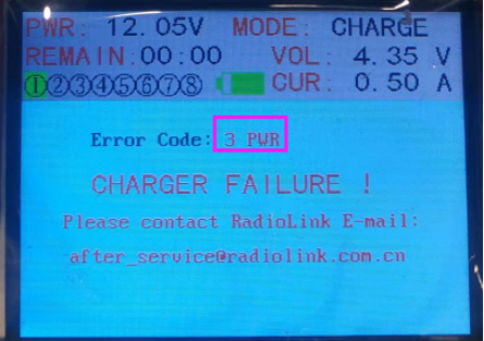
2. The firmware of CB86-PLUS has been upgraded to the latest firmware, and there is an error code on the screen: number + PWR (such as 3PWR, see picture below). The voltage and current of the charger power supply meet the requirements (the power supply voltage is within 10.5V-15V, and the current is not less than 15A), the power supply the triangular socket of the power supply contains a ground wire, and the error code number + V still exists even after replacing the power supply. You can add anti-interference capacitors on CB86-PLUS to solve it by following the below steps.

How to add anti-interference capacitors on CB86-PLUS?
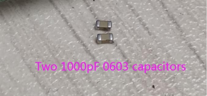
1. Prepare two 1000pF 0603 capacitors

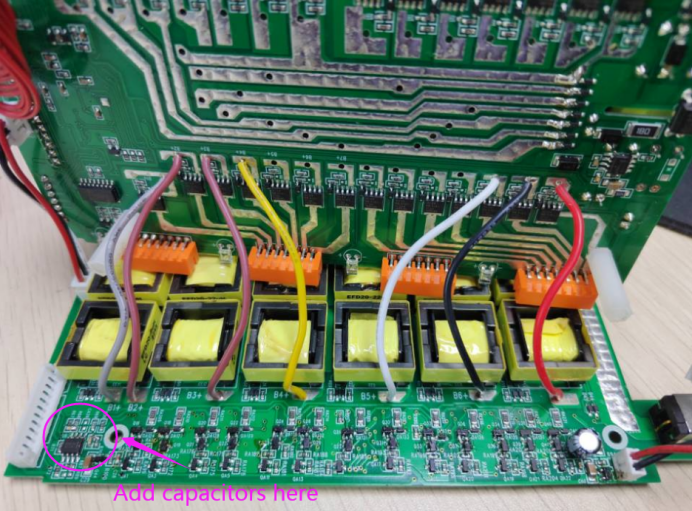
2. Disassemble CB86-PLUS and there are 3 main boards in the top, middle, and bottom. Two 1000pF 0603 capacitors need to be added to the bottom main board. Check the below picture for the area adding the capacitors.

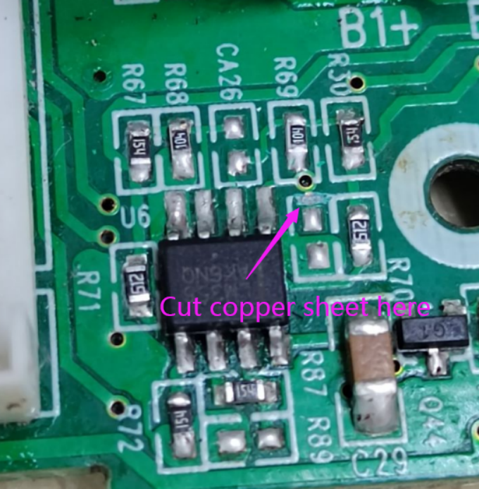
3. Cut copper sheet at the marked area. Check the below picture for the area cutting the copper sheet.

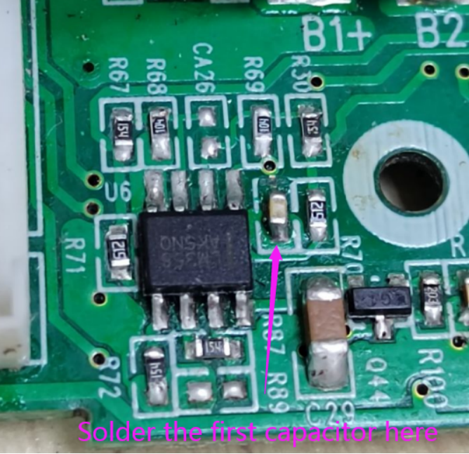
4. Solder the first capacitor. It looks as follows after the first capacitor is soldered.

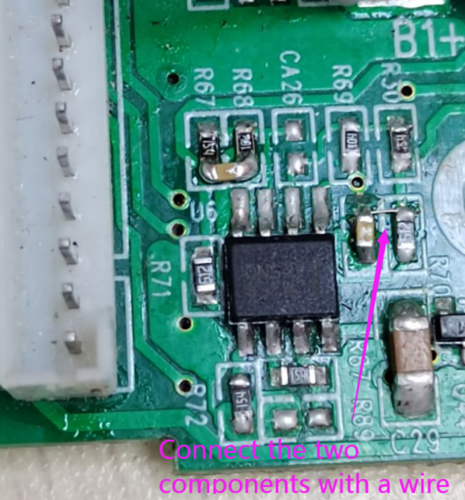
5. Use a wire (solder wire or solder paste) to short-circuit two component pads, as shown in the picture below:

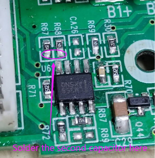
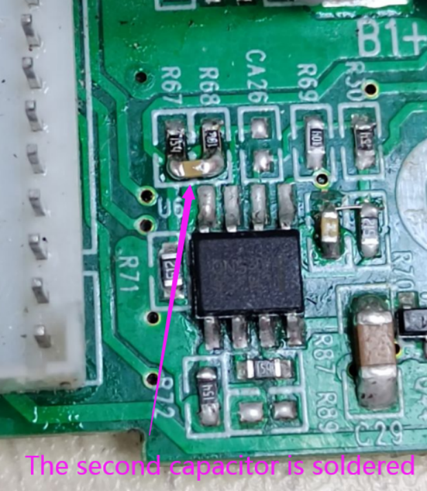
6. Solder the second capacitor. Check the below picture for the area soldering of the second capacitor.

7. It looks as follows after the second capacitor is soldered.

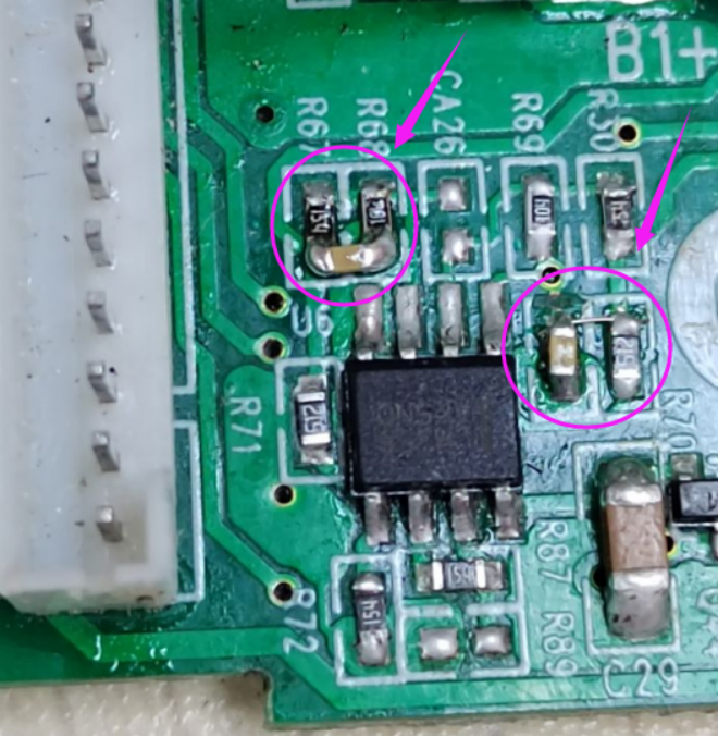
8. It looks as follows after the two capacitors are soldered.

If the mainboard of your CB86-PLUS is different from the one above, please refer to the following methods to add Zener diodes to the motherboard:
1. Check the picture below for the area adding Zener diodes.

2. Prepare a 10V 0805 zener diode. Be careful with the polarity. The polarity markings face to the right, as shown below.

3. It looks as follows after the Zener diode is soldered.
